Abstract
A major open challenge in neuroscience is the ability to measure and perturb neural activity in vivo from well defined neural sub-populations at cellular resolution anywhere in the brain. However, limitations posed by scattering and absorption prohibit non-invasive multi-photon approaches for deep (>2mm) structures, while gradient refractive index (GRIN) endoscopes are relatively thick and can cause significant damage upon insertion. Here, we present a novel micro-endoscope design to image neural activity at arbitrary depths via an ultra-thin multi-mode optical fiber (MMF) probe that has 5–10X thinner diameter than commercially available micro-endoscopes. We demonstrate micron-scale resolution, multi-spectral and volumetric imaging. In contrast to previous approaches, we show that this method has an improved acquisition speed that is sufficient to capture rapid neuronal dynamics in-vivo in rodents expressing a genetically encoded calcium indicator (GCaMP). Our results emphasize the potential of this technology in neuroscience applications and open up possibilities for cellular resolution imaging in previously unreachable brain regions.
OCIS codes: (170.2520) Fluorescence microscopy, (060.2350) Fiber optics imaging
1. Introduction
Multi-photon surface based imaging techniques have been successfully applied in neuroscience applications to image neurons and their activity at depths up to 1.6 mm relative to the cortical surface [1,2]. Many brain areas, however, lie beyond 1.6mm, especially in larger animals (e.g., ventral regions in non-human primates are 30mm deep relative to the dorsal surface). The design requirements for deep imaging deep in non-human primates (NHP) can be different compared to deep imaging systems designed for rodents. For example, one may wish to image acutely and target regions based on functional properties (stimuli responses), or target multiple different populations in the same animal to increase throughput.
To reach deeper, gradient refractive index lens (GRIN) based micro-endoscopes have been introduced [3–6]. However, GRIN lenses typically have a large diameter (0.5–1mm) and are difficult to fabricate at smaller diameters at long lengths due to their fragility. In addition, inserting such large diameter probes into the brain can cause significant damage and tissue displacement, which is why a common practice is to aspirate the brain above the region of interest to be imaged [7].
To assess expected brain deformation induced by inserting probes of different diameters we ran experiments in which probes of varying diameter were inserted into gel with brain like consistency, sparsely filled with tiny platinum beads (Fig. 1(a)). We used this phantom as a simple approximation to possible deformations induced by probe insertion [8, 9]. We imaged these phantom with stereo x-ray and registered beads position before and after probe insertion to assess the amount of tissue displacement and compression. We found that 1mm diameter probes induced large displacement (2.55 ± 1.93 mm) and compression (3.5mm shift of upper surface), while smaller diameter probes (0.1mm) induced shifts that were barely noticeable, suggesting the latter are better suited for acute-type experiments.
Fig. 1.
Simulations of expected brain tissue movement and compression. Small platinum beads (0.1–1mm in diameter) were embedded in agarose gel with brain like consistency and imaged with stereo x-ray system (only one view of the stereo pair is shown). Comparison between insertion of 1mm and 0.1mm probes. Dashed red lines denote surface deformation and false color image overlay shows beads movement (red - before insertion, blue - after insertion).
Here, we present a new lens-less micro-endoscope (Fiberscope) that uses an ultra-thin (120μm) multi-mode optical fiber (MMF) to achieve micron-scale resolution imaging in-vivo. MMF have been previously used in in-vivo neuroscience applications to deliver light for perturbing brain activity using optogenetics (e.g., [10]) and as single-pixel fluorescent imaging device (i.e., fiber-photometry [11,12]), but not for transmitting images since a speckle pattern is formed on the distal side when coherent light is focused on the proximal side [13]. Recent advances in wave front shaping (WFS) theory, however, suggest that if the input-output transformation of the fiber can be measured, arbitrary light patterns can be formed on the distal side of the fiber by aligning phases and generating constructive interference only at the desired location [14–18]. We sought to exploit these ideas for in-vivo functional calcium imaging by systematically addressing the open technical challenges.
2. System overview
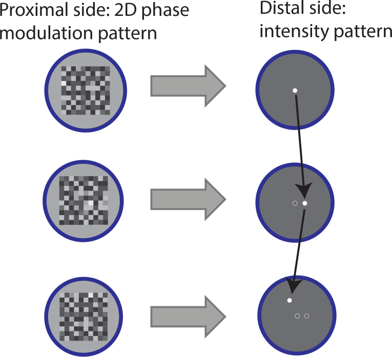
We use wave-front shaping to modulate the light hitting the proximal side of the fiber such that when it exits the distal side it generates a micron-scale spot at a desired location (Fig. 2). Fluorescent proteins in the sample are excited by the generated excitation spot and emit light that is collected by the same fiber. Emissions are measured with a sensitive photo-multiplier tube (PMT) on the distal side of the fiber. Images are obtained by raster scanning spots (Fig. 2 Each spot corresponds to a different phase modulation pattern that is presented on the proximal side of the fiber. Importantly, this approach enables random access allowing fast interrogation of region of interest at higher speeds. To address the challenging temporal requirements for real-time in-vivo full field image acquisition we adopt an approach proposed by [19], where phase modulation is generated on a fast, amplitude-only modulation device (digital mirror device, DMD).
Fig. 2.
Random access sampling with a multi-mode fiber..
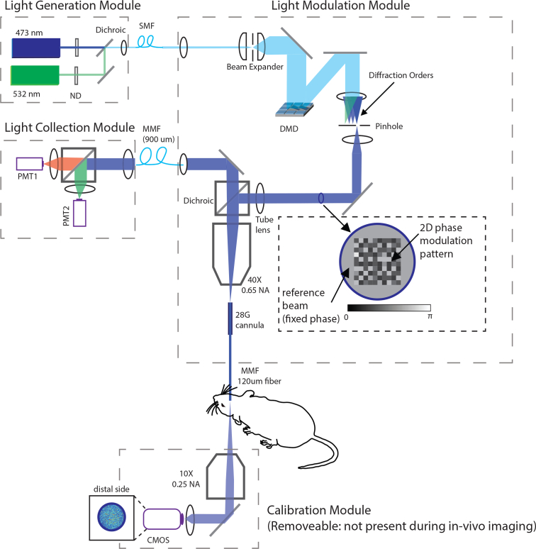
The optical path of the micro-endoscope is presented in Fig. 3. Overall, the system can be decomposed into four separate modules:
Light generation module. This module has one output: the combined light from two diode-pumped solid-state (DPSS) lasers (473nm, laser quantum and 532nm, CNI laser). Light is combined with a dichroic beamsplitter (FF495-Di03-25×36, Semrock) into a SMF (single-mode fiber, SM400 from Thorlabs) using a fiber collimator (F220FC-532, Thorlabs). Two wave-length illumination allows multi-spectral imaging (see section 4.4).
Light modulation and collection module. This module receives coherent input (SMF fiber from the light generation module). The incoming light is expanded onto the surface of a DMD (V7000, Vialux) and relayed through a pin hole (1000μm, P1000 from Thorlabs) that blocks all but the first diffraction order. The light is passed through a multi-band dichroic filter (LF405/488/532/635-A-000, Semrock) and focused using a 40X objective (RMS40X, Thorlabs) on the thin multi-mode fiber that goes into the brain (100μm core, 120μm total diameter, 0.66 NA from NeuroNexus). Fluorescent emissions are collected with the same fiber, relayed back to the dichroic and focused on a large diameter fiber (FG910UEC 910μm 0.22 NA, Thorlabs) that is used to connect this module to a light detection module.
Light Detection module: this module receives the large diameter MMF fiber with fluorescence emissions, splits it into two bands using a dichroic beam-splitter (Di02-R561-25×36, Semrock) and measures emissions with PMTs (Thorlabs PMTSS and Hamamatsu H7422-40). The analog signal is amplified, filtered (SR570, Standford Research Systems) and digitized using a high speed DAQ (USB2020, 8MS/s, Measurement computing).
Calibration module: this module acquires images of the distal side of the fiber using a 10X objective (RMS10, Thorlabs) and a fast CMOS camera (MQ013MG-ON from Ximea, up to 1800 fps).
Fig. 3.
Optical system design. See section 2 for details.
Such modular design has two clear advantages. First, it enables mechanical motion of the imaging fiber without affecting the way light is coupled to the fiber (i.e., it has no affect on the transmission matrix). Second, it reduces the weight of the module that needs to be mounted on a vertical translational stage.
2.1. Phase modulation with a digital mirror device
We use digital holography to generate phase patterns with amplitude-only modulation, generating diffraction pattern with the desired spatial phase distribution [20]. Here, we modify the approach of [19] and embed the desired spatial phase mask on a carrier function that is controlled by frequency f and rotation θ. Let x and y be the coordinates of a mirror on the DMD, then we define the carrier wave by:
The continuously valued mask function:
is then thresholded (> 0.5) to decide which mirrors are turned on and off. When this pattern is presented on the DMD, three main diffraction orders will be generated at the Fourier plane (0, ±1). If only one of those is allowed to pass through a pinhole, the result is the desired modulation phase Φ (x, y) that is up to a fixed offset. Multiple mirrors are grouped to represent a single desired phase at location Φ (x, y).
2.2. Transmission matrix and distal side pattern generation
We employ the Transmission Matrix method for measuring how input modes are scrambled to generate the observed speckle pattern. The full derivation of the Transmission Matrix approach can be found in [15]. Under a linear model, we assume that the complex observed output Eout linearly depends on the input modes:
where * denotes matrix multiplication and K is the so called transmission matrix. The input field Ein is a 2D complex field that is controlled by the phase mask Φ (x, y):
In the above derivation, Ein is flattened to form a Nx1 vector, where N is the number of independent modes that can be controlled (in our case, N=4096, i.e. 64×64 modes). The complex output dimension equals the number of observed pixels on the distal side (roughly ∼10K).
If the calibration (mixing) matrix K is known, any desired pattern can be approximately synthesized by inverting the equation:
Note that in practice, we only synthesize phase modulation to increase efficiency, so the actual pattern that is generated is composed of the calculated phases of Ein_calc.
To measure K, one can present a large basis set of inputs:
where Eobserved are the measured complex fields that correspond to the set of complex input fields Ebasis. In our case, since 4096 input phases are controlled, dim(Ebasis) = 4096x4096.
Any basis function can be used to probe the transmission matrix. We experimented with few (random, Hadamard and a polar version of the Hadamard version) and ended up using the simple Hadamard which has the desired property HT = H−1:
where H(x, y, i) represents the i’th column in a 2D binary Hadamard matrix (i.e., reshaped from 4096×4096 to 64×64×4096).
To recover the complex output Eobserved we use an interferometric method proposed by [15]. The input field is padded with a constant phase reference. The two fields (reference, and 64×64 input modes) go through interference in the fiber such that there is no need for a separate reference arm. If the input pattern is phase shifted by a fixed amount α, then the observed intensity will vary according to the following equation:
where Iα represents the measured power at a given pixel. If we define P ≜ r̄K * E and , we can recover the complex value P since:
and
Notice that once we know P, we can recover K up to an unknown scale.
2.3. Mechanical design
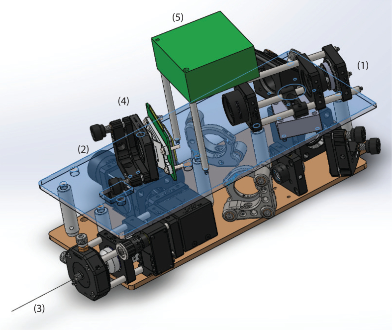
To reduce manufacturing costs, we used off-the-shelf components and mounted the optics between two aluminum boards (Fig. 4). The design essentially folds the beam to reduce the overall form factor. This imaging module was mounted on a vertical translation stage (LS300, Thorlabs) to translate the imaging fiber without affecting the way phases were coupled to the proximal side. All Solidworks design files are publicly available [21].
Fig. 4.
Mechanical system design. See section 2.3 for details. Main components highlighted: (1) SMF entry port for a incoming light, (2) exit port for fluorescence emissions (large diameter MMF fiber), (3) thin (120μm) optical fiber used for imaging, (4) DMD, (5) DMD PCB controller.
2.4. Code optimization
To speed up calculations we wrote a custom C++ code that uses Cublas (Cuda optimized matrix library for GPU). Further speed up was obtained by implementing a parallel Lee Hologram generator function on the GPU (10K holograms in less than 1.4 sec). Its output is represented as a packed binary image that can be uploaded faster to the DMD (∼6.5 sec). All code is publicly available [21].
3. Methods
3.1. Enhancement factor metric
One of the key factors determining SNR in our system is the peak intensity generated at the center of the point spread function. In previous studies (e.g. [19]) SNR was quantified as the ratio between the peak and the average intensity of the background, a quantity termed the Enhancement Factor (EF).
The peak intensity can be several orders of magnitude brighter than the background and if both the peak and background are measured with a single exposure with a standard cameras that has a limited dynamic range, it can lead to strong bias and over-estimation of the EF.
To overcome this difficulty we devised a procedure in which multiple images of the fiber are taken under varying neutral density filters. All images are then merged back to form a single high dynamic range (HDR) image from which both peak and background can be reliably estimated without concerns of under or over exposed pixels.
For a given image taken with neutral density n, a dark image is subtracted and all pixels that are over-exposed or under-exposed are removed (we use 5% and 95% percentile values of the 12-bit camera range to define over and under exposures). The final HDR image is constructed using the remaining valid pixels using the following equation:
Finally, the enhancement factor is defined as Ipeak/Iavg where Iavg is the average of the HDR image in the fiber core region after a 5×5 pixel region has been cropped around the Ipeak’s location.
3.2. Animal experiments
All procedures have been approved by the Massachusetts Institute of Technology Institutional Animal Care and Use Committee and conform to NIH standards. Wild type mice (C56BL/6) obtained from Jackson Labs were anesthetized with isoflurane (1–2%). A small borehole (∼300–500μm) was drilled and 50–100nl of AAV9-hSynGCaMP6s was pressure injected using a custom pump (25nl/minute) to deliver the GCaMP gene. We allowed 2–3 weeks of recovery and virus expression prior to imaging. Mice were then anesthetized again and a slightly larger craniotomy was performed to expose the brain. We used a thin wall hypodermic needle (28G) as reinforcement on the upper part of the fiber, leaving ∼2–5mm of fiber exposed for insertion (the needle was not pushed in the brain). Animals were then raised on a custom movable translation stage in small increments until the fiber punctured through the dura and entered the brain. At the end of the imaging session, animals were euthanized with a lethal dose of pentobarbital.
4. Experimental results
4.1. SNR and enhancement factor
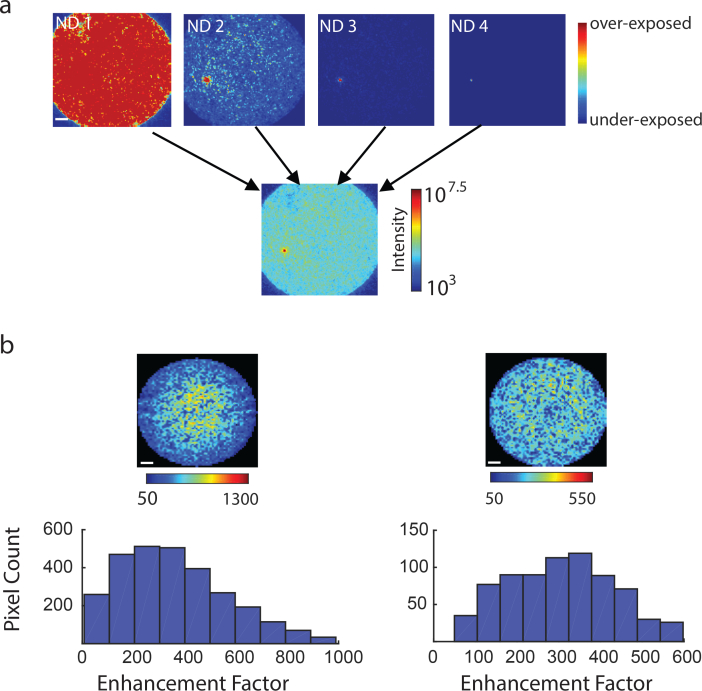
Following the procedure described in section 3.1, we constructed a HDR image of the fiber after generating a spot at a single location (Fig. 5(a)). We then repeated this procedure and generated spots in all possible locations in the core by acquiring HDR image per spot location. We found that the distribution of EF values can vary significantly as a function of the coupling at the proximal side. Empirically, when more central modes were excited, a skewed EF distribution was observed and central pixels had higher EF compared to pixels in the periphery (Fig. 5(b) left). In contrast, after a slightly shift of the incident angle a more uniform distribution of EF across the core could be achieved, albeit with somewhat lower EF values (Fig. 5(b), right)
Fig. 5.
Enhancement Factor Estimation. a) Images of the fiber taken under increasing levels of ND filters are combined to form HDR image. b) Two examples of observed distribution of enhancement factor values across the core.
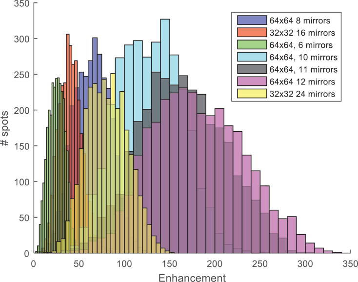
Another important factor determining the amplitude of the point spread function (PSF) is the number of input modes used and how many mirrors are assigned per input mode. Selecting these two parameters constrain the number of pixels that remain free to represent the constant reference arm. We experimented with 32×32, 64×64 and 96×96 modes and 8–12 mirrors per mode and found that the optimal combination with our DMD (V7000, Vialux, 1024×768 resolution) is 64×64 (4096 modes), where each mode is represented by 12 mirrors (Fig. 6). Thus, the actual pattern that is modulated is 768×768, where the remainder 128×768 mirrors represent the reference beam.
Fig. 6.
Reference and modes trade-off. Enhancement factor distribution as a function of number of input modes and number of mirrors assigned per mode.
4.2. Point spread function
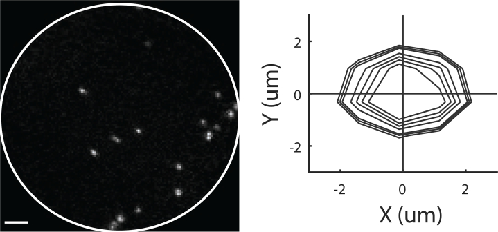
To assess the optical quality we measured the PSF along the emission path by imaging 0.99um fluorescent micro-spheres (FCDG006, Banglabs, Fig. 7). We modeled the PSF as a 2D Gaussian
and fitted the data to the observed intensities. We found that the full width half maximum is 2.10±0.25 um (mean, std), with estimated SNR of 1.39±0.1.
Fig. 7.
Point Spread Function. The in plane resolution of the system was estimated by imaging 0.99μm fluorescent beads and fitting 2D Gaussian to the data. The distribution of such fits are shown on the right.
4.3. Volumetric imaging
The ability to image away from the tip in the brain is important since neuron close to the tip are more likely to be damaged [22]. In the domain of microendoscopy, most approaches image at a fixed distance away from the tip to overcome this difficulty (but see [23]).
In our setup, when the calibration camera is focused on the fiber tip, the TM will map input phases to that plane. However, the imaging plane of the calibration camera can be translated downward. By doing this, the TM will still map input phases to the imaging plane and allow to form spots away from the fiber tip. Thus, It is possible to find phases needed to raster scan at different Z distances away from the tip, essentially acquiring a volume without the need to physically move the fiber during imaging (Fig. 8(a)).
Fig. 8.
Volumetric Imaging. a) Measuring transmission matrix (TM) with a camera focused on the tip can be used to generate spots on the tip. Measuring the TM with a camera that is focused at distance z from the tip can be used to generate spots at distance d from the fiber tip. b) Five sections of the same sample obtained at increasing distances from the fiber tip, collected without moving the fiber (i.e., with five different transmission matrices).
To assess our ability to form excitation spots away from the fiber tip in a scattering medium we imaged 15μm micro-spheres embedded in 2% intra-lipid agarose (Fig. 8). To quantify how well we can form an excitation spot in this scattering medium, we measured the separability of the bead relative to the background using the d’ sensitivity index:
where μX and σX are the average and standard deviation intensity in region X. We found that the separability index increased as the imaging plane got closer to 100 μm, suggesting the sharpest focus was obtained at that Z-section (Fig. 8(b)). This technique may be suitable for acquiring volumes in samples with sparse fluorescent labeling.
4.4. Multi-spectral imaging
In some neuroscience applications it is desired to excite a subset of the field of view with one wavelength while monitoring the remainder with another wavelength. For example, one may wish to stimulate a given neuron with a red-shifted ChR2 variant [24], while monitoring the rest of the field of view using GCaMP.
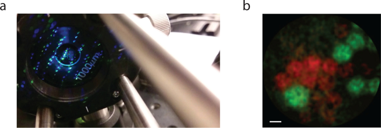
A nice advantage of using the pinhole for phase modulation in combination with two illumination sources is that we can rapidly switch between them by adjusting the carrier wave function used to construct the hologram. The grating equation nλ = d sin α + sin β shows that for a given incident angle α, the n ’th order reflection angle β will depend on the wavelength λ. In our setup, with a reasonable incident angle (∼40–65deg), one can get ∼0.5deg difference in the reflected blue and green beams (both share the same incident angle), which maps to 1mm spatial difference for the first diffraction order at distances > 200mm. By selecting the carrier wave frequency and rotation we can shift the position of the first diffraction order of one wave-length relative to the pinhole such that only that one will pass through (Fig. 9(a)). Our setup (Fig. 3) also allows simultaneous acquisition of multi-spectral tissue using a single wave-length excitation. For example, Fig. 9(b) shows an overlay of two images obtained from the two PMTs when two different types of micro-spheres were mixed together (i.e., both excited by blue-wavelength but differing in their emission spectra).
Fig. 9.
Multi-spectral imaging. a) Wavelength selection. The two diffracted wavelengths (blue, green) are spatially disjoint at the Fourier plane after being reflected from the DMD. Only one is allowed to pass through the pinhole at the center. Changing the carrier wave frequency and rotation steers either the blue or the green beams into the pinhole. b) Imaging of two different types of fluorescent micro-spheres with different emissions spectra (scale-bar: 10μm). Image depicts overlay of two images obtained from the two PMTs.
4.5. Biological tissue imaging
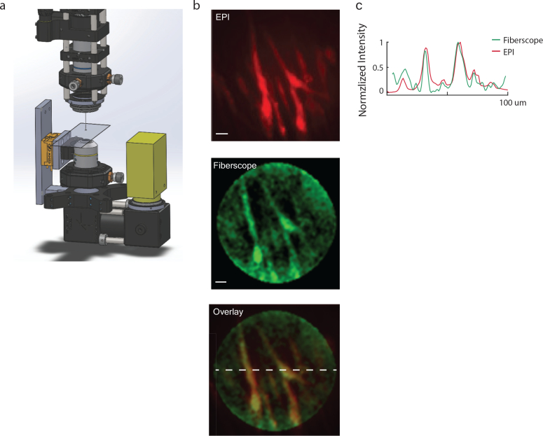
Biological fluorescence can be 10–1000× dimmer compared to fluorescent micro-spheres. To assess photon collection efficiency in more realistic conditions we imaged baby hamster kidney cells (BHK) expressing GFP. Our setup (Fig. 10(a)) is comprised of a sample on a glass slice sandwiched between the micro-endoscope (top) and an epi-fluorescence imaging microscope (bottom), where the latter provided a “ground-truth” image. We found that BHK cells were sufficiently bright to be captured with our imaging system using a high NA fiber (Fig. 11(a)) and that the acquired images had high correlation to the ground truth data (Fig. 12(b)).
Fig. 10.
Static In-vitro Imaging. a) Schematics of experimental setup. A glass side mounted with a sample was placed between the fiber microendoscope (top) and an epi-fluorescence microscope (bottom), where the latter served as ground truth. b) Imaging of baby hamster kidney cells expression eGFP. c) Intensity cross section of the overlay image. (scale-bar: 11μm)
Fig. 11.
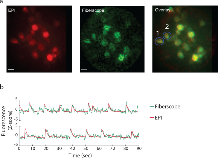
Dynamic In-vitro imaging. a) A similar experimental setup to the one shown in 10a was used to image hippocampal neuronal tissue culture expressing GCaMP6f. b) Time profile of two cells (highlighted in (a)).
Fig. 12.
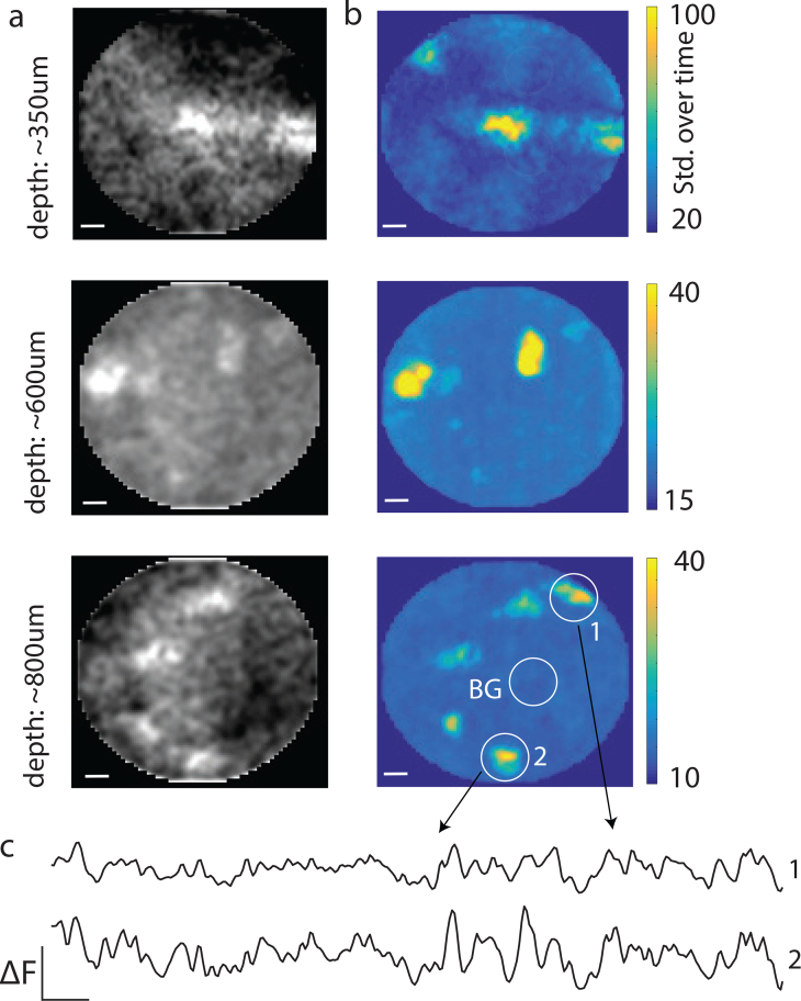
Dynamic in-vivo imaging. a) Imaging in-vivo neurons expressing GCaMP6f. Imaging plane was fixed at ∼100μm away from the fiber tip. The fiber was inserted slowly into the tissue and videos were acquired at multiple depths. Images show the average intensity over time. b) Same location as (a), but showing standard deviation over time, which correlated directly with the amount of neural activity observed. c) Temporal traces from two example neurons after background subtraction.
Next, we studied dynamic samples (i.e., neuronal activity) by imaging a thin hippocampal neuronal tissue culture expressing GCaMP6f [25]. We recorded full frame (100×100 μm at a rate of ∼7–15Hz by sub-sampling (every other pixel) and increasing the diameter of the PSF to ∼2μm. Multiple neurons were observed within the FOV (Fig. 11(a)). Spontaneous activity was observed across the population (Fig. 11(b)). The fluorescence time course measured with the fiber was in good agreement with epi microscope measurements (mean correlation : 0.54, n=6, note: the somewhat noisy measurements obtained with the fiber micro-endoscope were later traced to noise originating from one of the micro-controller controlling the PMT). We used up to 0.6mW laser power during these experiments and did not observe any significant photo-bleaching effects.
Finally, we tested the system by imaging dynamic neuronal activity in-vivo. We targeted primary visual cortex in wild-type mice that went through viral injection of GCaMP. We slowly inserted the fiber to the brain in steps of ∼50μm and imaged at each depth until we reached depth of 1 mm. Upon fiber insertion, several neurons appeared in the field of view (Fig. 10(a)) and drifted outward (towards the periphery) as the fiber was pushed in (see Visualization 1 (41.8MB, mov) [21] over time (Fig. 10(b)). Activity was strongly localized to active neurons compared to background (see background subtracted temporal traces in Fig. 10(c)).
4.6. Nuisance factors
A key assumption made so far is that the TM remains fixed throughout an experiment. However, several factors can change the transmission matrix. First, any fiber deformation is likely to change the scrambling and destroy the ability to form spots.
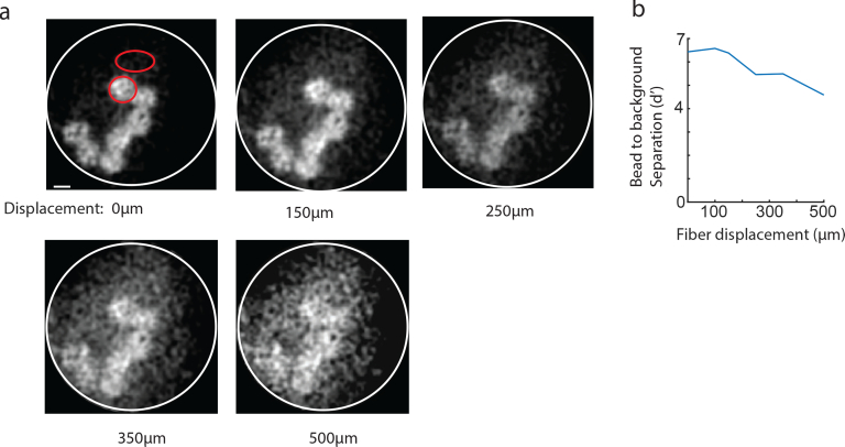
To address this concern we experimented with bending a long fiber in the middle while monitoring the images of fluorescent micro-spheres beneath the tip. We found that slight perturbation of the fiber position does not abruptly destroy the ability to form spots, but instead the effect is gradual and slowly degrades the SNR. This can be nicely visualized in Fig. 13(a), where beads can be easily recognized even after the fiber was shifted by 500 μm. To precisely quantify this we used the separability index d’ (13(b)), which indicated that even at displacement of 500 μm, one can still detect an object relative to the noisy background. Obviously, one would like to allow larger tolerances on fiber bending and one way forward is to engineer fibers with custom refractive profiles that may be less susceptible for such deformation (as proposed by [26]).
Fig. 13.
Gradual image deterioration after fiber bending. a) fluorescent micro-spheres were imaged with a long fiber. The middle part of the fiber was precisely translated while images were obtained to assess maximal bending allowed. b) Quantification of foreground (micro-spheres) to background SNR using the d’ measure (estimated at the two red highlighted regions in (a)).
Another nuisance factor that can change the TM is temperature. Temperature changes can lead to index change and different expansion of the two materials forming the core and cladding, leading to different coupling of light in the fiber. Although changes in room temperature aren’t a cause for concern (and indeed, once a fiber is calibrated in room temperature, the TM is robustly maintained over hours and days), inserting a fiber into warm brain tissue can cause significant changes.
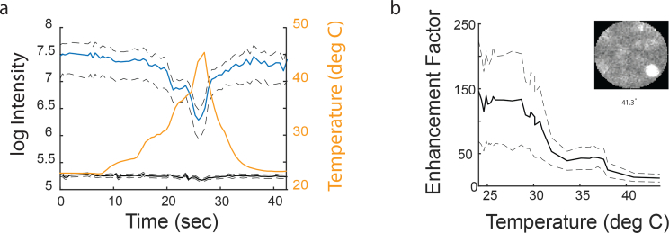
To assess the severity of such nuisance factor we calibrated a fiber in room temperature and continuously measured the EF across several formed spots while slowly increasing and recording the temperature using a sensitive temperature sensor (TMP36, Analog Devices). We found that temperature shifts of 20°C caused a significant reduction in the peak intensity of the generated spots (Fig. 14(a), blue curve), while background intensity remained roughly the same (Fig. 14(a), black curve). This mapped directly to a significant reduction of EF values (almost 10×, see Fig. 14(b)). Nevertheless, even with such extreme low EF values, images of fluorescent micro-spheres could still be obtained (see small inset in Fig. 14(b)). Thus, for in-vivo experiments it may be beneficial to calibrate the fiber at warmer temperature.
Fig. 14.
Enhancement Factor temperature fluctuations. a) Intensity of generated point spread function at various locations as a function of fiber temperature. Blue: peak intensity at the PSF, black: avg. intensity of background, yellow: approximated fiber temperature. b) Enhancement factor deterioration as a function of temperature. Small inset: image of a fluorescent bead taken at 41C after a calibration at 25C.
5. Discussion
We present a new micro-endoscope imaging system that uses WFS on a DMD to control light in a single MMF. To the best of our knowledge, this is the first demonstration of using MMF to image live cells and in-vivo neurons and represents a significant improvement over single pixel imaging fiber photometry [12]. The Image quality in our existing design is far from the fundamental limit and future designs will benefit greatly from improved mechanical stability (fiber coupling on the proximal side), precise temperature control, and higher EF with high-definition DMD and multi-photon imaging [27]. Nevertheless, even with the existing (non-optimal) implementation, we demonstrate sufficient capability to acquire images allowing identification of fine features at the neuronal scale.
A key improvement over previously proposed methods employing LC-SLM [28–32] is the ability to rapidly scan a large field of view and capture calcium events, while maintaining sufficient spatial resolution to resolve cellular details.
The proposed design has a field of view and resolution that depends on the imaging plane distance from the tip (see [32]. The field of view equals the core diameter when imaging plane is set to the tip, and gradually increases as the imaging plane is farther away from the tip. However, this comes at a price of reduced resolution since the effective NA is reduced at such peripheral locations. Even though PSF excitation spots can be formed at distances up to 500 μm away from the tip (in air), we found that imaging in highly scattering media such as the brain prohibit imaging at distances exceeding 100 μm.
We believe this type of microendoscope will be useful for imaging sparsely labeled neural populations expressing GCaMP in regions where the population is heterogeneous and nearby neurons may serve very different function. For example, identification of neurons projecting to a specific region among neighboring neurons which may be projecting to another region. Fluorescent labeling of such sparse neurons could be accomplished with retrograde labeling [33].
A large fraction of initial laser power (500mW) is lost through multiple optical stages, where the largest loss is after retaining only one diffraction order. We typically obtained 5–8 mW at the tip, but found that only 0.6mW is sufficient for imaging biological fluorescence without generating significant photo-bleaching (over several minutes of continuous imaging).
The proposed micro-endoscope is primarily designed for head restraint animals since fiber bending of more than 1mm is likely to degrade SNR to a point where individual neurons can no longer be discriminated from the background. However, preliminary results from testing various fibers types [26] suggests fiber engineering is likely to reduce motion sensitivity, increase SNR which could lead to solutions for freely behaving preparations. The proposed fiber-scope addresses critical needs for deep minimally-invasive brain functional imaging: small cross-section, micron-scale resolution, real time capture of neuronal dynamics including random access scanning, high-collection efficiency, multi-spectral capability, and volumetric imaging. Therefore, we expect this approach will open new avenues for addressing circuit level questions in deep brain regions that have thus far been unreachable with existing imaging modalities [34,35], especially in larger animals, such as non-human primates.
5.1. Supplementary material
Videos showing the calibration process and examples of neuronal imaging are available at [21], Visualization 1 (41.8MB, mov) .
Acknowledgments
We would like to thank Ian Wickersham for providing samples of BHK cells, Or Shemesh and Ed Boyden for providing the GCaMP6 neuronal tissue culture and discussions throughout the project.
Funding
McGovern Institute for Brain Research internal seed money; Life Sciences Research Foundation and Howard Hughes Medical Institute; National Institute of Health (REY026436A).
Disclosures
The authors declare that there are no conflicts of interest related to this article.
References and links
- 1.Horton N. G., Wang K., Kobat D., Clark C. G., Wise F. W., Schaffer C. B., Xu C., “In vivo three-photon microscopy of subcortical structures within an intact mouse brain,” Nat. Photonics 7, 205–209 (2013). 10.1038/nphoton.2012.336 [DOI] [PMC free article] [PubMed] [Google Scholar]
- 2.Ouzounov D. G., Wang T., Wang M., Feng D. D., Horton N. G., Cruz-Hernández J. C., Cheng Y.-T., Reimer J., Tolias A. S., Nishimura N., Xu C., “In vivo three-photon imaging of activity of GCaMP6-labeled neurons deep in intact mouse brain,” Nat. Methods 14, 388–390 (2017). 10.1038/nmeth.4183 [DOI] [PMC free article] [PubMed] [Google Scholar]
- 3.Bocarsly M. E., Jiang W.-C., Wang C., Dudman J. T., Ji N., Aponte Y., “Minimally invasive microendoscopy system for in vivo functional imaging of deep nuclei in the mouse brain,” Biomed. Opt. Express 6, 4546–4556 (2015). 10.1364/BOE.6.004546 [DOI] [PMC free article] [PubMed] [Google Scholar]
- 4.Szabo V., Ventalon C., De Sars V., Bradley J., Emiliani V., “Spatially selective holographic photoactivation and functional fluorescence imaging in freely behaving mice with a fiberscope,” Neuron 84, 1157–1169 (2014). 10.1016/j.neuron.2014.11.005 [DOI] [PubMed] [Google Scholar]
- 5.Mekhail S. P., Arbuthnott G., Chormaic S. N., “Advances in fibre microendoscopy for neuronal imaging,” Optical Data Processing and Storage 2, 30–42 (2016). 10.1515/odps-2016-0003 [DOI] [Google Scholar]
- 6.Ghosh K. K., Burns L. D., Cocker E. D., Nimmerjahn A., Ziv Y., Gamal A. E., Schnitzer M. J., “Miniaturized integration of a fluorescence microscope,” Nat. Methods 8, 871–878 (2011). 10.1038/nmeth.1694 [DOI] [PMC free article] [PubMed] [Google Scholar]
- 7.Barretto R. P. J., Schnitzer M. J., “In vivo microendoscopy of the hippocampus,” Cold Spring Harb. Protoc. 2012, 1092–1099 (2012). 10.1101/pdb.prot071472 [DOI] [PMC free article] [PubMed] [Google Scholar]
- 8.Weickenmeier J., de Rooij R., Budday S., Steinmann P., Ovaert T., Kuhl E., “Brain stiffness increases with myelin content,” Acta Biomaterialia 42, 265–272 (2016). 10.1016/j.actbio.2016.07.040 [DOI] [PubMed] [Google Scholar]
- 9.Hamzavi N., Tsang W. M., Shim V. P. W., “Nonlinear elastic brain tissue model for neural probe-tissue mechanical interaction,” in “2013 6th International IEEE/EMBS Conference on Neural Engineering (NER),” (2013), pp. 1119–1122. [Google Scholar]
- 10.Ohayon S., Grimaldi P., Schweers N., Tsao D. Y., “Saccade modulation by optical and electrical stimulation in the macaque frontal eye field,” J. Neurosci. 33, 16684–16697 (2013). 10.1523/JNEUROSCI.2675-13.2013 [DOI] [PMC free article] [PubMed] [Google Scholar]
- 11.Kim C. K., Yang S. J., Pichamoorthy N., Young N. P., Kauvar I., Jennings J. H., Lerner T. N., Berndt A., Lee S. Y., Ramakrishnan C., Davidson T. J., Inoue M., Bito H., Deisseroth K., “Simultaneous fast measurement of circuit dynamics at multiple sites across the mammalian brain,” Nat. Methods 13, 325–328 (2016). 10.1038/nmeth.3770 [DOI] [PMC free article] [PubMed] [Google Scholar]
- 12.Gunaydin L. A., Grosenick L., Finkelstein J. C., Kauvar I. V., Fenno L. E., Adhikari A., Lammel S., Mirzabekov J. J., Airan R. D., Zalocusky K. A., Tye K. M., Anikeeva P., Malenka R. C., Deisseroth K., “Natural neural projection dynamics underlying social behavior,” Cell 157, 1535–1551 (2014). 10.1016/j.cell.2014.05.017 [DOI] [PMC free article] [PubMed] [Google Scholar]
- 13.Goodman J. W., Speckle Phenomena in Optics: Theory and Applications (Roberts Publishers, 2010). [Google Scholar]
- 14.Vellekoop I. M., Lagendijk A., Mosk A. P., “Exploiting disorder for perfect focusing,” Nat. Photonics 4, 320–322 (2010). 10.1038/nphoton.2010.3 [DOI] [Google Scholar]
- 15.Popoff S. M., Lerosey G., Carminati R., Fink M., Boccara A. C., Gigan S., “Measuring the transmission matrix in optics: an approach to the study and control of light propagation in disordered media,” Phys. Rev. Lett. 104, 100601 (2010). 10.1103/PhysRevLett.104.100601 [DOI] [PubMed] [Google Scholar]
- 16.Psaltis D., Papadopoulos I., Farahi S., Moser C., “Imaging using multi-mode fibers,” in “Optics in the Life Sciences,” (Optical Society of America, 2013), p. BM4A.1. [Google Scholar]
- 17.Čižmár T., Dholakia K., “Shaping the light transmission through a multimode optical fibre: complex transformation analysis and applications in biophotonics,” Opt. Express 19, 18871–18884 (2011). 10.1364/OE.19.018871 [DOI] [PubMed] [Google Scholar]
- 18.Cižmár T., Dholakia K., “Exploiting multimode waveguides for pure fibre-based imaging,” Nat. Commun. 3, 1027 (2012). 10.1038/ncomms2024 [DOI] [PMC free article] [PubMed] [Google Scholar]
- 19.Conkey D. B., Caravaca-Aguirre A. M., Piestun R., “High-speed scattering medium characterization with application to focusing light through turbid media,” Opt. Express 20, 1733–1740 (2012). 10.1364/OE.20.001733 [DOI] [PubMed] [Google Scholar]
- 20.Lee W.-H., Computer-generated Holograms: Techniques and Applications (Elsevier, 1978). [Google Scholar]
- 21.Ohayon S., “Design files and source code for fiber microscope,” https://github.com/dicarlolab/Fiberscope (2017).
- 22.Polikov V. S., Tresco P. A., Reichert W. M., “Response of brain tissue to chronically implanted neural electrodes,” Journal of Neuroscience Methods 148, 1–18 (2005). 10.1016/j.jneumeth.2005.08.015 [DOI] [PubMed] [Google Scholar]
- 23.Sato M., Motegi Y., Yagi S., Gengyo-Ando K., Ohkura M., Nakai J., “Fast varifocal two-photon microendoscope for imaging neuronal activity in the deep brain,” Biomed. Opt. Express 8, 4049–4060 (2017). 10.1364/BOE.8.004049 [DOI] [PMC free article] [PubMed] [Google Scholar]
- 24.Klapoetke N. C., Murata Y., Kim S. S., Pulver S. R., Birdsey-Benson A., Cho Y. K., Morimoto T. K., Chuong A. S., Carpenter E. J., Tian Z., Wang J., Xie Y., Yan Z., Zhang Y., Chow B. Y., Surek B., Melkonian M., Jayaraman V., Constantine-Paton M., Wong G. K.-S., Boyden E. S., “Independent optical excitation of distinct neural populations,” Nat. Methods 11, 338–346 (2014). 10.1038/nmeth.2836 [DOI] [PMC free article] [PubMed] [Google Scholar]
- 25.Chen T.-W., Wardill T. J., Sun Y., Pulver S. R., Renninger S. L., Baohan A., Schreiter E. R., Kerr R. A., Orger M. B., Jayaraman V., Looger L. L., Svoboda K., Kim D. S., “Ultrasensitive fluorescent proteins for imaging neuronal activity,” Nature 499, 295–300 (2013). 10.1038/nature12354 [DOI] [PMC free article] [PubMed] [Google Scholar]
- 26.Caravaca-Aguirre A. M., Piestun R., “Single multimode fiber endoscope,” Opt. Express 25, 1656 (2017). 10.1364/OE.25.001656 [DOI] [PMC free article] [PubMed] [Google Scholar]
- 27.Morales-Delgado E. E., Psaltis D., Moser C., “Two-photon imaging through a multimode fiber,” Opt. Express 23, 32158–32170 (2015). 10.1364/OE.23.032158 [DOI] [PubMed] [Google Scholar]
- 28.Barankov R., Mertz J., “High-throughput imaging of self-luminous objects through a single optical fibre,” Nat. Commun. 5, 5581 (2014). 10.1038/ncomms6581 [DOI] [PMC free article] [PubMed] [Google Scholar]
- 29.Kolenderska S. M., Katz O., Fink M., Gigan S., “Scanning-free imaging through a single fiber by random spatio-spectral encoding,” Opt. Lett. 40, 534–537 (2015). 10.1364/OL.40.000534 [DOI] [PubMed] [Google Scholar]
- 30.Choi Y., Yoon C., Kim M., Yang T. D., Fang-Yen C., Dasari R. R., Lee K. J., Choi W., “Scanner-free and wide-field endoscopic imaging by using a single multimode optical fiber,” Phys. Rev. Lett. 109, 203901 (2012). 10.1103/PhysRevLett.109.203901 [DOI] [PMC free article] [PubMed] [Google Scholar]
- 31.Kim D., Moon J., Kim M., Yang T. D., Kim J., Chung E., Choi W., “Toward a miniature endomicroscope: pixelation-free and diffraction-limited imaging through a fiber bundle,” Opt. Lett. 39, 1921–1924 (2014). 10.1364/OL.39.001921 [DOI] [PubMed] [Google Scholar]
- 32.Papadopoulos I. N., Farahi S., Moser C., Psaltis D., “High-resolution, lensless endoscope based on digital scanning through a multimode optical fiber,” Biomed. Opt. Express 4, 260–270 (2013). 10.1364/BOE.4.000260 [DOI] [PMC free article] [PubMed] [Google Scholar]
- 33.Tervo D. G., Hwang B.-Y., Viswanathan S., Gaj T., Lavzin M., Ritola K., Lindo S., Michael S., Kuleshova E., Ojala D., Huang C.-C., Gerfen C., Schiller J., Dudman J., Hantman A., Looger L., Schaffer D., Karpova A., “A designer aav variant permits efficient retrograde access to projection neurons,” Neuron 92, 372–382 (2017). 10.1016/j.neuron.2016.09.021 [DOI] [PMC free article] [PubMed] [Google Scholar]
- 34.Seidemann E., Chen Y., Bai Y., Chen S. C., Mehta P., Kajs B. L., Geisler W. S., Zemelman B. V., “Calcium imaging with genetically encoded indicators in behaving primates,” Elife 5, e16178 (2016). 10.7554/eLife.16178 [DOI] [PMC free article] [PubMed] [Google Scholar]
- 35.Li M., Liu F., Jiang H., Lee T. S., Tang S., “Long-Term Two-Photon imaging in awake macaque monkey,” Neuron 93, 1049–1057 (2017). 10.1016/j.neuron.2017.01.027 [DOI] [PubMed] [Google Scholar]


