Abstract
A label-free sensor, based on the combination of silicon photonic bandgap (PBG) structures with immobilized molecular beacon (MB) probes, is experimentally developed. Complementary target oligonucleotides are specifically recognized through hybridization with the MB probes on the surface of the sensing structure. This combination of PBG sensing structures and MB probes demonstrates an extremely high sensitivity without the need for complex PCR-based amplification or labelling methods.
OCIS codes: (160.5293) Photonic bandgap materials, (040.6040) Silicon, (130.0130) Integrated optics, (220.4610) Optical fabrication, (280.1415) Biological sensing and sensors
1. Introduction
The use of oligonucleotides, short sequence nucleic acid strands, as indicators related to different biological functions is attracting a great interest during the last years. Some examples of these oligonucleotides are miRNAs, siRNAs or tRNAs, which play an important role in the regulation of gene expression [1–3], cell differentiation and proliferation [4–7], developmental timing [8–11], neural development [12] and apoptosis [13], among others. Moreover, the dysregulation of some of these oligonucleotide functions are also linked to several diseases, such as diabetes [14–16], neurodegenerative disorders [17–19] and cancer [20–23], making them perfect candidates to be used as clinical diagnostic and therapeutic biomarkers. In this context, the development of high-throughput, sensitive, and rapid oligonucleotides detection methods has become an important topic of research for the biomedical community.
Northern blot and real-time quantitative polymerase reaction (qPCR) techniques are currently considered the benchmark methods for oligonucleotides detection [24,25]. Despite it is used for the identification of several novel miRNAs [26], northern blot analysis provides a poor sensitivity, requires large amounts of sample input and is extremely laborious and time-consuming [27]. In contrast, qPCR can cover a broad range of oligonucleotide concentrations with a relatively high sensitivity, but it requires using highly purified targets, which can introduce a large variability and lead to inaccurate analyses [28]. Furthermore, labelling process is indeed a major requirement for these assay methods in order to increase both sensitivity and selectivity, making the detection slower, expensive and less reliable [29,30].
On the other hand, label-free detection technologies are rapidly evolving as alternative means for detecting a wide range of biomolecules in a simpler and more efficient way [31]. Among the different transduction technologies considered for these developments, planar integrated photonic technology presents advantages such as high sensitivity, compactness, high multiplexing level, shorter time to result, need of very low sample and reagent volumes, immunity to electromagnetic interferences and compatibility with CMOS (Complementary Metal-Oxide-Semiconductor) technology fabrication [32–34]. Oligonucleotides detection has already been demonstrated using photonic based sensors such as ring resonators [35–38], photonic crystals [38,39], Mach-Zehnder interferometers [40,41] or bimodal waveguides [42], exhibiting outstanding performance.
In this work, we report the development of a planar integrated photonic sensor for label-free oligonucleotide detection, comprising a photonic bandgap (PBG) structure biofunctionalized with molecular beacon (MB) recognition probes. The combination of these two transduction and biorecognition elements has allowed obtaining a very high spectral sensitivity towards the detection of target oligonucleotides while keeping a sensor footprint below 100 µm2.
2. Sensor concept
2.1. Photonic bandgap sensing structures
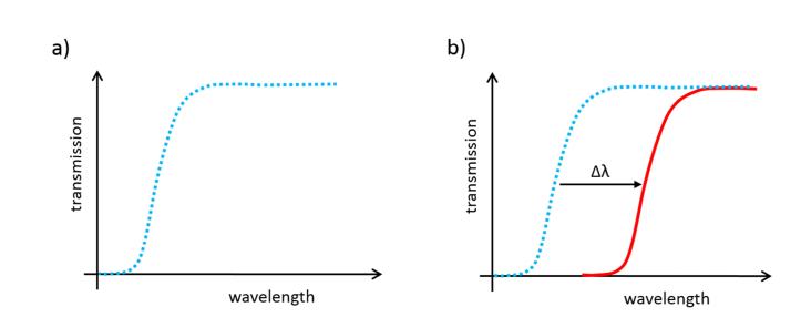
PBG structures, which are created by introducing a periodic modulation in the refractive index of the photonic structure, are one of the most promising candidates for the creation of high performance analysis devices [43,44]. In these structures, the position of the PBG, i.e., the spectral range where the propagation of the light is not allowed due to the periodicity of the structure, is shifted when a target analyte/substance interacts with them due to the local variation of the refractive index that is produced, as shown in Fig. 1. So, the extend of the biointeraction (or the amount of analyte accumulated on the surface) can be detected and quantified in real time by monitoring the shift of the PBG of the sensing structure.
Fig. 1.
Ideal transmission spectra for a PBG structure a) before the biomolecular interaction and b) after the biomolecular interaction, where a shift of the PBG is produced.
One of the most relevant characteristics of PBG structures as sensors is that their periodic configuration allows increasing the sensitivity on account of the enhanced interaction of the optical field with the targets due to the slow-wave effect [45,46], which makes the detection of very low analyte concentrations possible. In addition, their extremely reduced size, typically in the range of several tens of µm2, allows integrating many of these sensing structures on a much reduced area to perform a multi-analyte detection. Thus, PBG designs are a ground-breaking class of refractive-index-sensitive structures to monitor chemical and/or biochemical binding events.
2.2. Molecular beacon probes
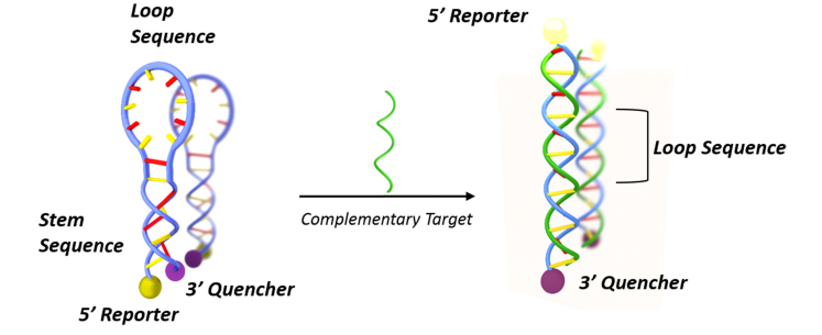
A MB probe consists on a single stranded oligonucleotide having a stem-loop configuration in its initial state [47,48]. Once hybridized with the complementary strand, the MB opens the stem adopting the double helix configuration. The typical application of MB is depicted in Fig. 2 [49], where a fluorescent label (reporter) and a quencher are attached to the 5′ and 3′ ends of the MB, respectively. Thus, when the hybridization takes place, the conformational change in the MB separates the quencher from the reporter, restoring the fluorescence. This fluorescence-based MB approach is widely used for oligonucleotide detection in homogeneous assays [50,51], but its performance is limited by the difficulty of detecting the small fluorescence changes produced by small oligonucleotide concentrations. Very few examples are found where the MB is used in an heterogeneous assay being immobilized onto a solid substrate [52,53].
Fig. 2.
Schematic explanation of the working principle of a fluorescence-based MB probe for oligonucleotide detection.
In the present work, instead of using the fluorescence-based configuration previously described, we directly immobilized MB on the surface of the PBG sensing structure, as shown in Fig. 3. In this way, the hybridization of the target oligonucleotides with the MB probes will induce a change in the response of the photonic sensing structure not only due to hybridization events, as it happens for typical linear oligonucleotide probes, but also by the contribution of the conformational change of the MB probes.
Fig. 3.
Scheme of the hybridization event having the MBs immobilized on the surface of a photonic structure.
3. PBG sensing structure design
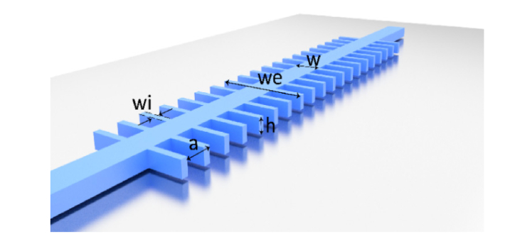
The PBG sensing structure used in this work consists on a silicon 1D periodic configuration created by introducing straight transversal elements in a single mode waveguide placed on top of a silicon oxide lower cladding, as shown in Fig. 4. The optimal configuration of the PBG sensing structure was determined by means of Plane Wave Expansion (PWE) and Finite-Difference Time-Domain (FDTD) simulations, considering a refractive index of nSi = 3.4777 for the silicon and of nSiO2 = 1.444 for the silicon oxide.
Fig. 4.
Schematic representation of the 1D PBG sensing structure. Note that it is considered that the silicon periodic structure is placed on top of a silicon oxide lower cladding.
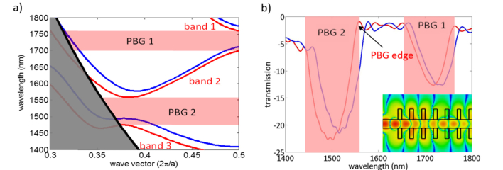
First, PWE simulations were done using MIT Photonic Bands (MPB) software in order to obtain the band diagrams for the different potential configurations of the periodic structure. In these simulations, TE modes were considered, as PBGs only appear for this polarization in periodic structures having a dielectric continuity. Additionally, only modes having an even in-plane symmetry were analyzed, as only those will be excited when accessing the periodic structure using a single mode waveguide. An example of band diagram for TE even modes is shown in Fig. 5(a), where it can be observed that up to two PBGs can potentially appear (between the first and the second bands and between the second and the third bands). From these simulations, the position of the PBG edges of the periodic structure was determined when considering a water upper cladding (nwater = 1.333) as well as their sensitivity to bulk refractive index variations.
Fig. 5.
(a) Example of MPB band diagram of the 1D PBG sensing structure. Bands depicted in red and blue colors represent the band diagram for a water (n = 1.333) and a silicon oxide (n = 1.444) upper cladding, respectively. Up to two PBGs can appear (depicted in shaded red color): one between the first and the second guided bands and another between the second and the third guided bands. The grey shaded area depicts the band diagram region being below the light line of the silicon oxide; modes within this region will not be confined in the vertical direction and will leak into the silicon oxide lower cladding, so they are not considered for determining the PBGs position. (b) Example of CST transmission spectrum of the 1D PBG sensing structure. Transmission spectra for a water and a silicon oxide upper cladding are depicted in red and blue colors, respectively. The two PBGs observed in the MPB band diagrams are also obtained in these simulations. The inset shows the electric field distribution (TE mode) along the PBG sensing structure at λ = 1550 nm.
Then, FDTD simulations were carried out using CST Microwave Studio to obtain the transmission spectral response for those configurations having any of their PBG edges located at 1550 nm. The simulation region considered a 750nm-high silicon oxide lower cladding and a 750nm-high upper cladding above the PBG sensing structure, and a 3000nm width in the transversal direction. The boundary conditions were all open add space and a symmetry plane was specified, located in the center of the waveguide and along the light propagation direction, as electric plane so as to reduce the simulation time. An example of FDTD transmission spectrum is shown in Fig. 5(b), where an inset of the electric field distribution (TE mode) along the PBG sensing structure at λ = 1550 nm is inserted. In these simulations, we looked for those configurations of the periodic structure providing a deep PBG region and a sharp PBG edge.
The selected optimal configuration consisted on a single mode waveguide of width w = 460nm and height h = 220nm where transversal elements, of width wi = 120nm and length we = 1500nm, are introduced with a periodicity of a = 380nm. This configuration has the upper edge of its second PBG located at 1550 nm for a water upper cladding and provides a theoretical sensitivity to bulk refractive index variations of 175 nm/RIU (Refractive Index Units).
4. Fabrication and biofunctionalization
4.1. Photonic chip fabrication
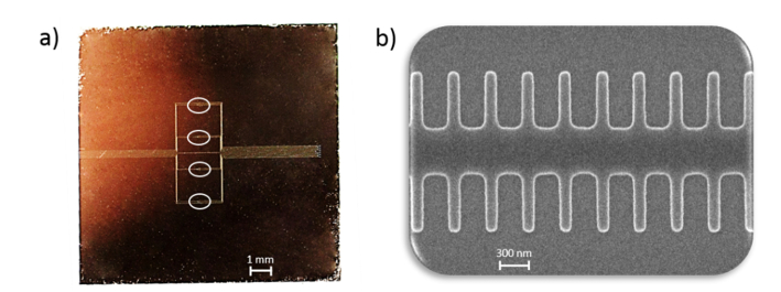
Figure 6(a) shows a picture of the fabricated photonic chip created in a silicon-on-insulator (SOI) substrate using e-beam lithography with an acceleration voltage of 100 keV and inductively coupled plasma etching of the top silicon layer. Four PBG sensor pairs separated a distance of 1.5 mm were included in the chip in order to have the possibility of biofunctionalizing each of them in a different manner. Each pair comprises two PBG sensing structures having a different width of the transversal elements (wi = 120nm and wi = 140nm) in order to compare their sensing performance. Figure 6(b) shows a scanning electron microscope (SEM) image of one of the PBG sensing structures fabricated in the photonic chip. The chip was accessed at the input and the output via 70 nm-deep shallow etch 1D grating couplers. A multi-mode interferometer (MMI) splitter was used before each PBG sensor pair in order to excite both structures using the same access grating coupler, what allows reducing the number of input coupling structures. Finally, three reference waveguides were also included in order to ease the alignment process when measuring the photonic chip.
Fig. 6.
(a) Image of the photonic chip fabricated in SOI technology. The circles depict the position of each PBG sensor pair. (b) SEM image of a fabricated PBG sensing structure.
4.2. Biofunctionalization
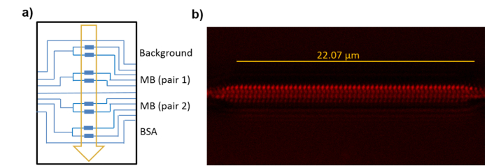
Thiol-ene coupling (TEC) chemistry was selected for the covalent attachment of thiolated MB probes to the previously derivatized PBG sensing structures [54], following the biofunctionalization schematic diagram shown in Fig. 7(a). This approach allows the biocompatible, rapid and homogeneous biofunctionalization of the structure under mild conditions, using UV light. To this aim, alkene groups are introduced on the chip surface by immersion in vinyltriethoxysilane, 2% in toluene, for 2 hours. Then, after rinsing the chip with acetone and curing it at 80°C for 30 minutes, an aqueous solution of thiolated MB probes, 10 μM, is spotted over two of the four PBG sensor pairs of the chip and irradiated at 254 nm for 30 seconds to induce photoimmobilization. Finally, the chip is washed with PBS-T, ultrapure water and dried with air. Immobilization densities of 14 pmol/cm2 were obtained following this procedure, as previously reported in [54]. The entire surface of the waveguide was homogeneously covered with MB probes as demonstrated by confocal fluorescence microscopy (CFM) analysis using the probe labelled with a fluorophore (Fig. 7(b)). One of the other two sensor pairs of the chip was spotted with a blocking solution of BSA (Bovine Serum Albumin, 2% in ultrapure water), incubated for 2 h, and rinsed. The lasting pair of the chip was left unmodified. Those two pairs were used as references.
Fig. 7.
(a) Schematic diagram of the photonic chip biofunctionalization. Each PBG sensing structure is represented by a blue rectangle. The arrow indicates the microfluidic flow direction. (b) CFM image of the biofunctionalized PBG structure using fluorophore labelled MB probes.
A 35-mer target oligonucleotide sequence was selected for the sensing experiments and a Cy5 fluorescent label was included to confirm the effective hybridization with the MBs immobilized in the surface of the PBG sensing structures once the experiment is finished. An optimal MB probe was designed for the detection of this target oligonucleotide. In Table 1 respective sequences are indicated.
Table 1. 35-mer target oligonucleotide sequence and optimal MB probe sequence designed for its detection.
| 5′ | 3′ | Sequence (5′-3′) | |
|---|---|---|---|
| Target | Cy5 | AUCGACUUAAUGCUAAUCGUGAUAGGGGUGUCGU | |
| MB | SH | ATCGACACCCCTATCACGATTAGCATTAAGTCGAT |
5. Experimental results and discussion
5.1. Experimental setup
The biofunctionalized chip is assembled with a polydimethylsiloxane (PDMS) flow cell having a 400 µm-wide and 50 µm-high microfluidic channel for sample delivery. The assembled chip is placed in an automated optical characterization setup able to continuously acquire the spectral response of all the photonic structures within the chip. Light from a continuous sweep tunable laser (Keysight 81980A) is coupled to the access grating couplers using a fiber aspheric collimator (Thorlabs CFS2-1550-APC). The light from the output grating couplers is collected with an objective (20X Olympus Plan Achromat, 0.4 NA) and measured using an infrared (IR) camera (Xenics Xeva-1.7-320). The interrogation platform is controlled using a software programmed in LabVIEW able to synchronize the continuous sweep of the laser with the image acquisition of the IR camera via a trigger signal in order to obtain the spectra of the photonic structures with the desired spectral resolution. The system is configured to acquire the spectra in the range from 1520 nm to 1620 nm with a sweeping speed of 10 nm/s (i.e., the spectra of all the photonic structures within the chip is acquired every 10 seconds) and a spectral resolution of 20 pm (the IR camera works at 500 fps). The target solutions are flowed using a syringe pump working in withdraw mode and set to a constant flow rate of 20 μl/min.
5.2. Oligonucleotide biorecognition experiment
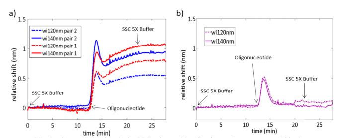
Figure 8 shows the spectral evolution of the upper edge of the second PBG of the sensing structures for the oligonucleotide biorecognition experiment. This PBG edge was initially located at λ≈1570nm and λ≈1595nm for the configurations having a width of the transversal elements of wi = 120nm and wi = 140nm, respectively. Firstly, saline-sodium citrate (SSC) buffer 5X was flowed to obtain the baseline of the sensing structures. Secondly, a solution of 0.5 µM of the fluorescence labeled target oligonucleotide, in SSC 5X, was flowed over them for 10 minutes. Finally, SSC 5X was flowed again in order to remove any non-hybridized oligonucleotide present in the medium. Note that the access section of the PBG sensor pair left unmodified (i.e., without the MB probes or the BSA blocking) was damaged and no output signal was measured for these sensors, thus leaving only the two structures blocked with BSA as references.
Fig. 8.
Spectral evolution of the PBG edge position for the sensing structures within the photonic chip when the target oligonucleotide is flowed over their surface. The sensing response for each PBG sensor pair is depicted in a different color and a different line format is used for each sensor within the pair (dashed line for wi = 120nm and solid line for wi = 140nm). (a) Sensing response for the PBG sensing structures being functionalized with the MB probes. (b) Sensing response for the PBG sensing structures blocked with BSA.
From Fig. 8(a), it can be observed that a significant shift of the PBG edge position is produced when the target oligonucleotide is flowed over the PBG sensing structures biofunctionalized with the MB probes. This shift, typical for binding processes [55–57], remains unchanged when SSC 5X buffer is flowed again, indicating that the target oligonucleotide effectively and irreversibly hybridizes with the MB probe under the given conditions. On the other hand, Fig. 8(b) shows that the PBG sensing structures blocked with BSA do not show a net shift when SSC 5X buffer is flowed again after the oligonucleotide flow, indicating that the blocking BSA layer properly avoids the unspecific adsorption of the target oligonucleotide to the PBG sensing structures.
Besides the response (or lack of response for the BSA blocked structures) towards the target oligonucleotide, a remarkable instantaneous shift of the PBG edge position is observed for all the sensing structures within the chip when the solution with the target oligonucleotide reaches the sensors. This sharp shift lasts only around 2-3 minutes and the PBG edge is sharply back-shifted again to the initial position, as it can be clearly seen for the blocked sensing structures. That “up-and-down” shift indicates that an accumulation of the target oligonucleotide was produced in the tubing in the interface between the initial SSC 5X buffer and the oligonucleotide solution, producing a spectral shift caused by the increase of the refractive index of the medium. Nevertheless, after this transitory behavior, the nominal concentration of the target oligonucleotide is recovered and the refractive index of the medium goes back to the initial value.
Regarding the sensitivity of the MB-functionalized PBG sensing structures towards the target oligonucleotide, net shifts of the PBG edge ranging from ~520 pm to even up to ~1100 pm were obtained. These shifts represent a significant improvement in the sensitivity compared to those obtained using ring resonator based sensors, which are typically below 100 pm [35,58], and are even higher to those obtained with those sensing structures using antibody-based amplification techniques [36]. Therefore, these shifts indicate a very high sensitivity of the selected PBG sensing structure towards small local refractive index variations being produced in its surface, as well as a very efficient recognition of the oligonucleotide targets by the MB probes used in the experiment.
Finally, it is worth noting the tremendous influence of the structural parameters of the PBG sensing structures on their sensitivity. From Fig. 8(a) it can be seen that the PBG edge shift increases from ~520 pm to ~950 pm when the width of the transversal elements is simply increased from wi = 120nm to wi = 140nm for the first PBG sensor pair (depicted with blue color); for the second PBG sensor pair (depicted with red color), the PBG edge shift increases from ~800 pm to ~1100 pm for that 20 nm increase of the width of the transversal elements. Therefore, by properly selecting the structural parameters of the PBG sensing structure used in this work, a significant improvement in the sensitivity can be obtained without the need of increasing the footprint. This is a great advantage compared to other typical configurations of photonic sensing structures as ring resonators, where the sensitivity is limited by its working principle, or interferometers, where achieving higher sensitivities implies significantly increasing the size of the structure. On the other hand, this high influence of the structural parameters on the sensitivity also means a lower tolerance to fabrication deviations, as it can be observed from the different PBG edge shifts obtained for sensing structures nominally having the same dimensions. Therefore, better fabrication reproducibility will be necessary for a repeatable and reliable operation of these sensors.
5.3. Fluorescence test
Once the oligonucleotide detection experiment was carried out, the PDMS flow cell was disassembled in order to measure the fluorescence of the labelled target oligonucleotide on the photonic chip. Fluorescence was observed selectively for the two PBG sensor pairs biofunctionalized with MB probes, as shown in Fig. 9(a). The quantification of that fluorescence is represented in Fig. 9(b), showing very high fluorescence intensity values on the positions where the MB probes were immobilized, thus confirming the recognition of the target oligonucleotides. On the other hand, the fluorescence intensity measured on the BSA blocked PBG sensing structures is extremely low, thus confirming the effectiveness of the blocking step.
Fig. 9.
(a) Fluorescence intensity observed on the photonic chip (left) after the oligonucleotide detection experiment and relative position on the chip (right). The shape of the microfluidic channel used in the experiment can be clearly observed. (b) Quantification of the fluorescence after the oligonucleotide detection experiment for the PBG sensor pairs.
6. Conclusion
While our PBG structures do not have theoretical significantly higher bulk sensitivities (175nm/RIU) than other sensing structures (e.g., ring resonators, 80nm/RIU), we have been able to observe a PBG edge shift that is much greater in magnitude. This is due to the combination of an extremely high surface sensitivity of the PBG structures and a redistribution of matter produced by the conformational change suffered by the MB probes upon hybridization.
Overall, the combination of the selected PBG sensing structures with the MB recognition probes has provided extremely high sensitivities towards the label-free detection of the target oligonucleotides, without the need of using any labelling method or increasing the much reduced footprint of the sensor. We expect that even higher sensitivities can be obtained by properly selecting the dimensions of the PBG structures, as observed from the obtained results, as well as by increasing the probe surface density [38,41]. This result opens the door for using this sensor configuration for the development of high sensitivity and highly multiplexed photonic based sensing chips for oligonucleotides detection with application in the biomedical field.
Funding
European Commission through the Horizon 2020 Program (ICT-644242 SAPHELY project).
Disclosures
The authors declare that there are no conflicts of interest related to this article.
References and links
- 1.He L., Hannon G. J., “MicroRNAs: small RNAs with a big role in gene regulation,” Nat. Rev. Genet. 5(7), 522–531 (2004). 10.1038/nrg1379 [DOI] [PubMed] [Google Scholar]
- 2.Gutierrez-Arcelus M., Ongen H., Lappalainen T., Montgomery S. B., Buil A., Yurovsky A., Bryois J., Padioleau I., Romano L., Planchon A., Falconnet E., Bielser D., Gagnebin M., Giger T., Borel C., Letourneau A., Makrythanasis P., Guipponi M., Gehrig C., Antonarakis S. E., Dermitzakis E. T., “Tissue-Specific Effects of Genetic and Epigenetic Variation on Gene Regulation and Splicing,” PLoS Genet. 11(1), e1004958 (2015). 10.1371/journal.pgen.1004958 [DOI] [PMC free article] [PubMed] [Google Scholar]
- 3.Debernardi S., Skoulakis S., Molloy G., Chaplin T., Dixon-McIver A., Young B. D., “MicroRNA miR-181a correlates with morphological sub-class of acute myeloid leukaemia and the expression of its target genes in global genome-wide analysis,” Leukemia 21(5), 912–916 (2007). 10.1038/sj.leu.2404605 [DOI] [PubMed] [Google Scholar]
- 4.Maute R. L., Schneider C., Sumazin P., Holmes A., Califano A., Basso K., Dalla-Favera R., “tRNA-derived microRNA modulates proliferation and the DNA damage response and is down-regulated in B cell lymphoma,” Proc. Natl. Acad. Sci. U.S.A. 110(4), 1404–1409 (2013). 10.1073/pnas.1206761110 [DOI] [PMC free article] [PubMed] [Google Scholar]
- 5.Lim L. P., Lau N. C., Garrett-Engele P., Grimson A., Schelter J. M., Castle J., Bartel D. P., Linsley P. S., Johnson J. M., “Microarray analysis shows that some microRNAs downregulate large numbers of target mRNAs,” Nature 433(7027), 769–773 (2005). 10.1038/nature03315 [DOI] [PubMed] [Google Scholar]
- 6.Dunne J., Cullmann C., Ritter M., Soria N. M., Drescher B., Debernardi S., Skoulakis S., Hartmann O., Krause M., Krauter J., Neubauer A., Young B. D., Heidenreich O., “siRNA-mediated AML1/MTG8 depletion affects differentiation and proliferation-associated gene expression in t(8;21)-positive cell lines and primary AML blasts,” Oncogene 25(45), 6067–6078 (2006). 10.1038/sj.onc.1209638 [DOI] [PubMed] [Google Scholar]
- 7.Lin C. H., Jackson A. L., Guo J., Linsley P. S., Eisenman R. N., “Myc-regulated microRNAs attenuate embryonic stem cell differentiation,” EMBO J. 28(20), 3157–3170 (2009). 10.1038/emboj.2009.254 [DOI] [PMC free article] [PubMed] [Google Scholar]
- 8.Rideout E. J., Marshall L., Grewal S. S., “Drosophila RNA polymerase III repressor Maf1 controls body size and developmental timing by modulating tRNAiMet synthesis and systemic insulin signaling,” Proc. Natl. Acad. Sci. U.S.A. 109(4), 1139–1144 (2012). 10.1073/pnas.1113311109 [DOI] [PMC free article] [PubMed] [Google Scholar]
- 9.Hornstein E., Mansfield J. H., Yekta S., Hu J. K., Harfe B. D., McManus M. T., Baskerville S., Bartel D. P., Tabin C. J., “The microRNA miR-196 acts upstream of Hoxb8 and Shh in limb development,” Nature 438(7068), 671–674 (2005). 10.1038/nature04138 [DOI] [PubMed] [Google Scholar]
- 10.Schratt G. M., Tuebing F., Nigh E. A., Kane C. G., Sabatini M. E., Kiebler M., Greenberg M. E., “A brain-specific microRNA regulates dendritic spine development,” Nature 439(7074), 283–289 (2006). 10.1038/nature04367 [DOI] [PubMed] [Google Scholar]
- 11.Poethig R. S., “Small RNAs and developmental timing in plants,” Curr. Opin. Genet. Dev. 19(4), 374–378 (2009). 10.1016/j.gde.2009.06.001 [DOI] [PMC free article] [PubMed] [Google Scholar]
- 12.Fineberg S. K., Kosik K. S., Davidson B. L., “MicroRNAs Potentiate Neural Development,” Neuron 64(3), 303–309 (2009). 10.1016/j.neuron.2009.10.020 [DOI] [PubMed] [Google Scholar]
- 13.Chan J. A., Krichevsky A. M., Kosik K. S., “MicroRNA-21 Is an Antiapoptotic Factor in Human Glioblastoma Cells,” Cancer Res. 65(14), 6029–6033 (2005). 10.1158/0008-5472.CAN-05-0137 [DOI] [PubMed] [Google Scholar]
- 14.Saberi M., Bjelica D., Schenk S., Imamura T., Bandyopadhyay G., Li P., Jadhar V., Vargeese C., Wang W., Bowman K., Zhang Y., Polisky B., Olefsky J. M., “Novel liver-specific TORC2 siRNA corrects hyperglycemia in rodent models of type 2 diabetes,” Am. J. Physiol. Endocrinol. Metab. 297(5), E1137–E1146 (2009). 10.1152/ajpendo.00158.2009 [DOI] [PMC free article] [PubMed] [Google Scholar]
- 15.Walker M. D., “Role of MicroRNA in Pancreatic β-Cells: where More is less,” Diabetes 57(10), 2567–2568 (2008). 10.2337/db08-0934 [DOI] [PMC free article] [PubMed] [Google Scholar]
- 16.Muhonen P., Holthofer H., “Epigenetic and microRNA-mediated regulation in diabetes,” Nephrol. Dial. Transplant. 24(4), 1088–1096 (2008). 10.1093/ndt/gfn728 [DOI] [PMC free article] [PubMed] [Google Scholar]
- 17.Liu E. Y., Cali C. P., Lee E. B., “RNA metabolism in neurodegenerative disease,” Dis. Model. Mech. 10(5), 509–518 (2017). 10.1242/dmm.028613 [DOI] [PMC free article] [PubMed] [Google Scholar]
- 18.Perkins D. O., Jeffries C. D., Jarskog L. F., Thomson J. M., Woods K., Newman M. A., Parker J. S., Jin J., Hammond S. M., “microRNA expression in the prefrontal cortex of individuals with schizophrenia and schizoaffective disorder,” Genome Biol. 8(2), R27 (2007). 10.1186/gb-2007-8-2-r27 [DOI] [PMC free article] [PubMed] [Google Scholar]
- 19.Lee J. W., Beebe K., Nangle L. A., Jang J., Longo-Guess C. M., Cook S. A., Davisson M. T., Sundberg J. P., Schimmel P., Ackerman S. L., “Editing-defective tRNA synthetase causes protein misfolding and neurodegeneration,” Nature 443(7107), 50–55 (2006). 10.1038/nature05096 [DOI] [PubMed] [Google Scholar]
- 20.Goodarzi H., Liu X., Nguyen H. C. B., Zhang S., Fish L., Tavazoie S. F., “Endogenous tRNA-Derived Fragments Suppress Breast Cancer Progression via YBX1 Displacement,” Cell 161(4), 790–802 (2015). 10.1016/j.cell.2015.02.053 [DOI] [PMC free article] [PubMed] [Google Scholar]
- 21.Judge A. D., Robbins M., Tavakoli I., Levi J., Hu L., Fronda A., Ambegia E., McClintock K., MacLachlan I., “Confirming the RNAi-mediated mechanism of action of siRNA-based cancer therapeutics in mice,” J. Clin. Invest. 119(3), 661–673 (2009). 10.1172/JCI37515 [DOI] [PMC free article] [PubMed] [Google Scholar]
- 22.Lodes M. J., Caraballo M., Suciu D., Munro S., Kumar A., Anderson B., “Detection of Cancer with Serum miRNAs on an Oligonucleotide Microarray,” PLoS One 4(7), e6229 (2009). 10.1371/journal.pone.0006229 [DOI] [PMC free article] [PubMed] [Google Scholar]
- 23.Casanova-Salas I., Rubio-Briones J., Fernández-Serra A., López-Guerrero J. A., “miRNAs as biomarkers in prostate cancer,” Clin. Transl. Oncol. 14(11), 803–811 (2012). 10.1007/s12094-012-0877-0 [DOI] [PubMed] [Google Scholar]
- 24.Várallyay E., Burgyán J., Havelda Z., “MicroRNA detection by northern blotting using locked nucleic acid probes,” Nat. Protoc. 3(2), 190–196 (2008). 10.1038/nprot.2007.528 [DOI] [PubMed] [Google Scholar]
- 25.Benes V., Castoldi M., “Expression profiling of microRNA using real-time quantitative PCR, how to use it and what is available,” Methods 50(4), 244–249 (2010). 10.1016/j.ymeth.2010.01.026 [DOI] [PubMed] [Google Scholar]
- 26.Lagos-Quintana M., Rauhut R., Yalcin A., Meyer J., Lendeckel W., Tuschl T., “Identification of Tissue-Specific MicroRNAs from Mouse,” Curr. Biol. 12(9), 735–739 (2002). 10.1016/S0960-9822(02)00809-6 [DOI] [PubMed] [Google Scholar]
- 27.Streit S., Michalski C. W., Erkan M., Kleeff J., Friess H., “Northern blot analysis for detection and quantification of RNA in pancreatic cancer cells and tissues,” Nat. Protoc. 4(1), 37–43 (2009). 10.1038/nprot.2008.216 [DOI] [PubMed] [Google Scholar]
- 28.Graybill R. M., Bailey R. C., “Emerging Biosensing Approaches for microRNA Analysis,” Anal. Chem. 88(1), 431–450 (2016). 10.1021/acs.analchem.5b04679 [DOI] [PMC free article] [PubMed] [Google Scholar]
- 29.Seydack M., “Nanoparticle labels in immunosensing using optical detection methods,” Biosens. Bioelectron. 20(12), 2454–2469 (2005). 10.1016/j.bios.2004.11.003 [DOI] [PubMed] [Google Scholar]
- 30.Hempen C., Karst U., “Labeling strategies for bioassays,” Anal. Bioanal. Chem. 384(3), 572–583 (2006). 10.1007/s00216-005-3392-0 [DOI] [PubMed] [Google Scholar]
- 31.Schmidt S., Flueckiger J., Wu W., Grist S. M., Fard S. T., Donzella V., Khumwan P., Thompson E. R., Wang Q., Kulik P., Kirk J., Cheung K. C., Chrostowski L., Ratner D., “Improving the performance of silicon photonic rings, disks, and Bragg gratings for use in label-free biosensing,” Proc. SPIE 9166, 91660M (2014). 10.1117/12.2062389 [DOI] [Google Scholar]
- 32.Fan X., White I. M., Shopova S. I., Zhu H., Suter J. D., Sun Y., “Sensitive optical biosensors for unlabeled targets: A review,” Anal. Chim. Acta 620(1-2), 8–26 (2008). 10.1016/j.aca.2008.05.022 [DOI] [PMC free article] [PubMed] [Google Scholar]
- 33.Estevez M. C., Alvarez M., Lechuga L. M., “Integrated optical devices for lab-on-a-chip biosensing applications,” Laser Photonics Rev. 6(4), 463–487 (2012). 10.1002/lpor.201100025 [DOI] [Google Scholar]
- 34.Luchansky M. S., Bailey R. C., “High-Q optical sensors for chemical and biological analysis,” Anal. Chem. 84(2), 793–821 (2012). 10.1021/ac2029024 [DOI] [PMC free article] [PubMed] [Google Scholar]
- 35.Qavi A. J., Bailey R. C., “Multiplexed Detection and Label-Free Quantitation of MicroRNAs Using Arrays of Silicon Photonic Microring Resonators,” Angew. Chem. Int. Ed. Engl. 49(27), 4608–4611 (2010). 10.1002/anie.201001712 [DOI] [PMC free article] [PubMed] [Google Scholar]
- 36.Ramachandran A., Wang S., Clarke J., Ja S. J., Goad D., Wald L., Flood E. M., Knobbe E., Hryniewicz J. V., Chu S. T., Gill D., Chen W., King O., Little B. E., “A universal biosensing platform based on optical micro-ring resonators,” Biosens. Bioelectron. 23(7), 939–944 (2008). 10.1016/j.bios.2007.09.007 [DOI] [PubMed] [Google Scholar]
- 37.Qavi A. J., Kindt J. T., Gleeson M. A., Bailey R. C., “Anti-DNA:RNA Antibodies and Silicon Photonic Microring Resonators: Increased Sensitivity for Multiplexed microRNA Detection,” Anal. Chem. 83(15), 5949–5956 (2011). 10.1021/ac201340s [DOI] [PMC free article] [PubMed] [Google Scholar]
- 38.Hu S., Zhao Y., Qin K., Retterer S. T., Kravchenko I. I., Weiss S. M., “Enhancing the Sensitivity of Label-Free Silicon Photonic Biosensors through Increased probe Molecule Density,” ACS Photonics 1(7), 590–597 (2014). 10.1021/ph500075g [DOI] [Google Scholar]
- 39.Toccafondo V., García-Rupérez J., Bañuls M. J., Griol A., Castelló J. G., Peransi-Llopis S., Maquieira A., “Single-strand DNA detection using a planar photonic-crystal-waveguide-based sensor,” Opt. Lett. 35(21), 3673–3675 (2010). 10.1364/OL.35.003673 [DOI] [PubMed] [Google Scholar]
- 40.Sepúlveda B., Río J. S., Moreno M., Blanco F. J., Mayora K., Domínguez C., Lechuga L. M., “Optical biosensor microsystems based on the integration of highly sensitive Mach-Zehnder interferometer devices,” J. Opt. A 8(7), S561–S566 (2006). 10.1088/1464-4258/8/7/S41 [DOI] [Google Scholar]
- 41.Qin K., Hu S., Retterer S. T., Kravchenko I. I., Weiss S. M., “Slow light Mach-Zehnder interferometer as label-free biosensor with scalable sensitivity,” Opt. Lett. 41(4), 753–756 (2016). 10.1364/OL.41.000753 [DOI] [PubMed] [Google Scholar]
- 42.Huertas C. S., Fariña D., Lechuga L. M., “Direct and Label-Free Quantification of Micro-RNA-181a at Attomolar Level in Complex Media Using a Nanophotonic Biosensor,” ACS Sens 1(6), 748–756 (2016). 10.1021/acssensors.6b00162 [DOI] [Google Scholar]
- 43.Nunes P. S., Mortensen N. A., Kutter J. P., Mogensen K. B., “Refractive index sensor based on a 1D photonic crystal in a microfluidic channel,” Sensors (Basel) 10(3), 2348–2358 (2010). 10.3390/s100302348 [DOI] [PMC free article] [PubMed] [Google Scholar]
- 44.Dutta H. S., Pal S., “Design of a highly sensitive photonic crystal waveguide platform for refractive index based biosensing,” Opt. Quantum Electron. 45(9), 907–917 (2013). 10.1007/s11082-013-9697-x [DOI] [Google Scholar]
- 45.Povinelli M., Johnson S., Joannopoulos J., “Slow-light, band-edge waveguides for tunable time delays,” Opt. Express 13(18), 7145–7159 (2005). 10.1364/OPEX.13.007145 [DOI] [PubMed] [Google Scholar]
- 46.García J., Sanchis P., Martínez A., Martí J., “1D periodic structures for slow-wave induced non-linearity enhancement,” Opt. Express 16(5), 3146–3160 (2008). 10.1364/OE.16.003146 [DOI] [PubMed] [Google Scholar]
- 47.Wang K., Tang Z., Yang C. J., Kim Y., Fang X., Li W., Wu Y., Medley C. D., Cao Z., Li J., Colon P., Lin H., Tan W., “Molecular engineering of DNA: molecular beacons,” Angew. Chem. Int. Ed. Engl. 48(5), 856–870 (2009). 10.1002/anie.200800370 [DOI] [PMC free article] [PubMed] [Google Scholar]
- 48.Zheng J., Yang R., Shi M., Wu C., Fang X., Li Y., Li J., Tan W., “Rationally designed molecular beacons for bioanalytical and biomedical applications,” Chem. Soc. Rev. 44(10), 3036–3055 (2015). 10.1039/C5CS00020C [DOI] [PMC free article] [PubMed] [Google Scholar]
- 49.Tyagi S., Kramer F. R., “Molecular beacons: probes that fluoresce upon hybridization,” Nat. Biotechnol. 14(3), 303–308 (1996). 10.1038/nbt0396-303 [DOI] [PubMed] [Google Scholar]
- 50.Guo Q., Bai Z., Liu Y., Sun Q., “A molecular beacon microarray based on a quantum dot label for detecting single nucleotide polymorphisms,” Biosens. Bioelectron. 77, 107–110 (2016). 10.1016/j.bios.2015.09.031 [DOI] [PubMed] [Google Scholar]
- 51.Mei Z., Tang L., “Surface-Plasmon-Coupled Fluorescence Enhancement Based on Ordered Gold Nanorod Array Biochip for Ultrasensitive DNA Analysis,” Anal. Chem. 89(1), 633–639 (2017). 10.1021/acs.analchem.6b02797 [DOI] [PMC free article] [PubMed] [Google Scholar]
- 52.Li S., Wang Y., Gao C., Ge S., Yu J., Yan M., ““Signal-off” photoelectrochemical DNA sensing strategy based on target dependent DNA probe conformational conversion using CdS quantum dots sensitized TiO2 nanorods array as photoactive material,” J. Electroanal. Chem. 759, 38–45 (2015). 10.1016/j.jelechem.2015.06.007 [DOI] [Google Scholar]
- 53.Su Q., Wesner D., Schönherr H., Nöll G., “Molecular Beacon Modified Sensor Chips for Oligonucleotide Detection with Optical Readout,” Langmuir 30(47), 14360–14367 (2014). 10.1021/la504105x [DOI] [PubMed] [Google Scholar]
- 54.González-Lucas D., Bañuls M. J., García-Rupérez J., Maquieira Á., “Covalent attachment of byotinylated molecular beacons via thiol-ene coupling. A study on conformational changes upon hybridization and streptavidin binding,” Mikrochim. Acta 184(9), 3231–3238 (2017). 10.1007/s00604-017-2310-4 [DOI] [Google Scholar]
- 55.Morton T. A., Myszka D. G., Chaiken I. M., “Interpreting Complex Binding Kinetics from Optical biosensors: A Comparison of Analysis by Linearization, the Integrated Rate Equation, and Numerical Integration,” Anal. Biochem. 227(1), 176–185 (1995). 10.1006/abio.1995.1268 [DOI] [PubMed] [Google Scholar]
- 56.Srisa-Art M., Dyson E. C., deMello A. J., Edel J. B., “Monitoring of Real-Time Streptavidin-Biotin Binding Kinetics Using Droplet Microfluidics,” Anal. Chem. 80(18), 7063–7067 (2008). 10.1021/ac801199k [DOI] [PubMed] [Google Scholar]
- 57.Erickson D., Li D., Krull U. J., “Modeling of DNA hybridization kinetics for spatially resolved biochips,” Anal. Biochem. 317(2), 186–200 (2003). 10.1016/S0003-2697(03)00090-3 [DOI] [PubMed] [Google Scholar]
- 58.Scheler O., Kindt J. T., Qavi A. J., Kaplinski L., Glynn B., Barry T., Kurg A., Bailey R. C., “Label-free, multiplexed detection of bacterial tmRNA using silicon photonic microring resonators,” Biosens. Bioelectron. 36(1), 56–61 (2012). 10.1016/j.bios.2012.03.037 [DOI] [PMC free article] [PubMed] [Google Scholar]


