Abstract
The idea that embolized xylem vessels can be refilled while adjacent vessels remain under tension is difficult to accept if the cavitated vessels remain hydraulically connected to vessels under tension. A mechanism by which embolized conduits could be hydraulically isolated from adjacent conduits requires the existence of a non-zero contact angle and a flared opening into the bordered pit chamber such that a convex air-water interface forms at the entrance into the pit chamber. We measured the contact angle and pit chamber geometry for six species. The contact angle measured in the vessel lumen ranged between 42° to 55°, whereas the opening into the pit chamber ranged between 144° and 157°. If the surface properties within the pit chamber are similar to those in the lumen, a convex meniscus will form at the flared opening into the pit chamber. The maximum pressure difference between water in the lumen and gas in the pit chamber that could be stabilized by this interface was calculated to be within the range of 0.07 to 0.30 MPa.
Water transport in the xylem is vulnerable to disruption due to cavitation (Tyree and Sperry, 1989; Milburn, 1993). There is increasing evidence, based on measurements of hydraulic conductivity and changes in the volume of gas-filled conduits (Salleo et al., 1996; Canny, 1997; McCully et al., 1998; Zwieniecki and Holbrook, 1998; Pate and Canny, 1999; Tyree et al., 1999), that embolized xylem vessels may regain their ability to conduct transport water despite the persistence of negative pressures in adjacent conduits. The idea that embolized vessels could be refilled without pressurization of the entire xylem (such as occurs with root pressure; Sperry et al., 1987) suggests that xylem hydraulic conductivity is more dynamic than previously thought. How embolized vessels are refilled while adjacent vessels remain under tension, however, is not understood. A recent paper outlined a scenario for refilling (Holbrook and Zwieniecki, 1999), but did not examine in detail the proposed mechanism. In this paper we present measurements of xylem vessel structure and wall surface properties needed to quantitatively examine some of the features of this model. Embolism repair as outlined by Holbrook and Zwieniecki (1999) consists of three steps: movement of water into the embolized conduit; isolation of the refilling conduit such that the positive pressures needed to dissolve the trapped gas volume can occur; and stable reconnection to adjacent vessels under tension. In this paper we deal specifically with the question of hydraulic compartmentalization and address whether the structure of actual xylem vessels is consistent with the proposed mechanism.
The primary function of the xylem is to provide a pathway for water movement through the plant. Xylem vessels are formed from elongated cells (referred to as vessel elements) that at maturity have thick, lignified secondary cell walls and lack all cytoplasmic content (Esau, 1977; Zimmermann, 1983). Each vessel consists of a series of such cells in which the axial walls have been substantially perforated or removed to allow relatively unrestricted water movement in a longitudinal direction. Individual vessels do not extend throughout the length of the plant and water moves between vessels and to adjacent parenchyma cells through numerous small openings termed “pits” in the secondary walls. Pits between vessels typically have overarching walls that form a bowl-shaped chamber, giving them the name “bordered pits.” At the center of each bordered pit is the pit “membrane,” which is formed from the original primary walls and intervening middle lamella. The very small pores in the pit membrane are thought to prevent the spread of air embolisms between vessels (Zimmermann, 1983; Tyree and Sperry, 1989).
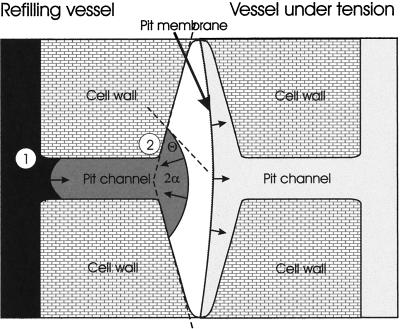
Removal of the gas within an embolized vessel requires positive pressure to force the gas into the surrounding liquid phase (Pickard, 1981; Yang and Tyree, 1992). To contain this pressurization, the perimeter of the vessel must, in effect, be sealed. The structure and the thickness of secondary walls contribute to their low permeability to water, making it unlikely that water can easily be pushed through the walls even when wood is wet. Pits, on the other hand, provide the primary path for water movement between vessels, raising the question of how they could function to separate the positive pressure in the refilling conduit from negative pressures in adjacent, water-filled vessels. For hydraulic compartmentalization to occur, the pits must function as a hydraulic valve, allowing the gas in the lumen to be pressurized without, at the same time, compressing the much smaller (approximately 10−5 times) volume of gas trapped within each bordered pit. Holbrook and Zwieniecki (1999) propose that the positive pressures required for gas dissolution are contained within refilling vessels by the formation of a convex gas-water interface within each pit chamber (Fig. 1). A convex curvature means that the force due to surface tension will oppose the hydrostatic pressure within the refilling lumen. As long as the positive pressures within the lumen do not exceed the force due to surface tension, the meniscus will be stable. The shape of this meniscus depends on the contact angle of the water with the vessel wall and the inclination of the walls of the pit chamber (Holbrook and Zwieniecki, 1999). In this paper we present measurements of contact angle and intervessel pit geometry for six species, allowing us to calculate the maximum pressures that could be contained within a refilling conduit according to the proposed mechanism.
Figure 1.
Diagram of bordered pit separating the refilling vessel (left) from the vessel under tension (right). As water enters into the bordered pit channel (1) it forms a concave meniscus such that the curvature of the meniscus pulls the water into the bordered pit. As the meniscus enters the pit chamber (2) it bows out forming a convex shape in which the force due to surface opposes further expansion into the border pit.
RESULTS
Mean contact angle (Θ) of water droplets placed on the inner surface of individual xylem vessels ranged from 42° to 55° (Table I). One-way analysis of variance indicates significant variation among species (F = 2.63 with 6 and 78 degrees of freedom; P = 0.022), however the Tuckey honest significant difference for unequal sample size test (Spjotvoll and Stoline, 1973) indicates a significant difference only between maple (Acer saccharum Marshall) and laurel (Laurus nobilis L.; P = 0.012).
Table I.
Measurements of contact angle of water (Θ) and angle of bordered pit chamber walls (2α)
| Species | Θ | sd | N | 2α | sd | N |
|---|---|---|---|---|---|---|
| ° | ° | |||||
| Rhizophora mangle L. | 47.3 | 16.80 | 6 | 148.2 | 6.01 | 11 |
| Fraxinas americana L. | 48.5 | 7.78 | 8 | 147.3 | 7.72 | 10 |
| Liriodendron tulipifera L. | 45.4 | 7.25 | 19 | 145.7 | 2.51 | 3 |
| A. saccharum Marshall | 55.0 | 9.90 | 18 | 150.6 | 5.65 | 7 |
| Nicotiana tabacum L. | 50.1 | 14.68 | 14 | 153.0 | 4.69 | 8 |
| L. nobilis L. | 42.0 | 8.89 | 16 | 155.8 | 5.49 | 7 |
Values represent the mean and sd of measurements from N individuals of each species.
Openings into bordered pits are typically elliptical in cross-section with the major axis rarely exceeding 3 μm and the minor axis being less than 1 μm (Table II). This opening leads to a straight-walled channel whose length depends, in part, on the thickness of the secondary wall. The channel, in turn, opens into a small chamber across the center of which is the pit membrane. Pit membranes are typically circular in shape and less then 5 μm in diameter (Table II). The one-half-angle across the flared opening of the pit chamber (α in Fig. 1) ranged from 73° to 78° (Table I). These values are within the range of what can be obtained from published images of wood structure (e.g. Schmid, 1965; Core et al., 1976; Butterfield and Meylan, 1980; Barnett, 1981; Zimmermann, 1983).
Table II.
Bordered pit dimensions
| Species | N | Pit Membrane Diameter | Pit Channel Dimensions
|
ΔPmax | |
|---|---|---|---|---|---|
| a | b | ||||
| μm | MPa | ||||
| R. mangle L. | 11 | 3.79 (0.87) | 1.84 (0.40) | 0.41 (0.08) | 0.25 |
| F. americana L. | 10 | 1.41 (0.15) | 0.65 (0.11) | 0.43 (0.09) | 0.30 |
| L. tulipifera L. | 11 | 4.09 (0.50) | 2.72 (0.45) | 1.71 (0.52) | 0.07 |
| A. saccharum Marshall | 9 | 4.52 (0.41) | 2.06 (0.21) | 0.45 (0.13) | 0.28 |
| N. tabacum L. | 12 | 5.02 (0.76) | 2.12 (0.42) | 1.06 (0.25) | 0.12 |
| L. nobilis L. | 7 | 3.19 (0.46) | 1.49 (0.22) | 0.42 (0.07) | 0.24 |
Diameters of pit membrane and major (a) and minor (b) axes of the bordered pit channel assuming an elliptical shape. ΔPmax is the maximum pressure difference that can exist between water in the refilling vessel and gas trapped in the border pit chamber without expansion of the water into the bordered pit chamber. ΔPmax was calculated as γGcos (Θ + a), where γ is the surface tension of water (0.0728 n m−1 at 20°C), G is the ratio of the perimeter to cross-sectional area of the pit channel (m−1), Θ is the contact angle determined for the vessel wall surface (Table I), and α is the inclination of the pit chamber wall (Table I).
DISCUSSION
The idea that transpiring plants might be able to repair cavitated xylem vessels is difficult to understand if the refilling vessel is hydraulically connected with conduits under tension. A key aspect of the model recently proposed by Holbrook and Zwieniecki (1999) is that it outlines a mechanism for the hydraulic compartmentalization of the refilling vessel from the rest of the transporting system. For this to occur, Θ must be greater than 0° and α + Θ must be greater than 90°. The measurements of contact angle and intervessel pit geometry reported here fulfill these specifications for all six species.
According to Holbrook and Zwieniecki (1999), the requirement for a non-zero contact angle arises from the need to prevent water that enters the gas-filled conduit from flowing along the wall surface and eventually coming into contact with an adjacent vessel. A non-zero contact angle means that the water will “bead” up on the inner surface of the vessels, rather than spreading out across the inner surface of the conduit. The second requirement defines the conditions needed for a convex gas:water meniscus to form within the bordered pit. Specifically, as water enters into the straight-walled channel of the bordered pit, the gas:water interface will be concave (provided Θ < 90°). Under these conditions both the hydrostatic pressure in the water and the force arising due to surface tension act in the same direction (Fig. 1), pulling water into the border pit. However, when the meniscus reaches the flared opening of the pit chamber, the change in the wall angle (α) will result in a convex interface if Θ + α > 90°. Because of the convex shape, the force arising from surface tension will oppose the hydrostatic pressure exerted by the water in the lumen (Fig. 1). The maximum pressure difference (ΔPmax) between gas in the refilling vessel and the gas trapped in the border pit that can be counterbalanced by a meniscus within the bordered pit can be calculated from the capillary equation (Nobel, 1983; Denny, 1993):
 |
where γ is the surface tension of water (0.0728 n m−1 at 20°C) and G is the ratio of the perimeter to cross-sectional area of the pit channel opening (per meter), in this case assumed to be an ellipse. For the species examined here, the maximum pressure difference that can be stabilized by the curvature of this interface ranges between 0.07 and 0.30 MPa. This value sets the maximum pressure that can be employed to force the air within the embolized vessel into solution.
Although we focus on embolism repair in this paper, we recognize that both xylem wall composition and the structure of bordered pits contribute to the overall function of the xylem as a water transport tissue. For example, the structure of bordered pits can be interpreted as a mechanism for increasing the surface area of the pit membrane and hence the hydraulic conductivity of the wood, without having to make large openings in the secondary walls that could decrease their strength. In conifers, the overarching walls of the pit chamber are thought to allow the torus to act like a valve in sealing off an aspirated conduit (Chapman et al., 1977). The non-zero contact angle of xylem walls is most likely due to the hydrophobic compound lignin (Sarkanen and Ludwig, 1971). Lignin has many effects, including increasing the compressive strength of conduit walls and making the wood more resistant to microbial and fungal attack. Its effect on wall surface chemistry, however, has not been recognized and most textbooks assume that the contact angle is 0° when demonstrating the inability of capillary rise in xylem vessels as a means of getting water to the top of a tree (e.g. Nobel, 1983). In contrast, the pit membrane, which is formed from the primary wall, is generally thought to consist primarily of cellulose microfibrils that are hydrophilic. This suggests that the contact angle for pit membranes is close to zero. However, lignin is present in some pit membranes (Meylan and Butterfield, 1982), suggesting that further examination of both the chemical and physical structure will contribute to our understanding of factors limiting the spread of embolisms from one vessel to another.
The results presented in this paper support the view that the positive pressures required for gas dissolution can co-occur with tension in adjacent conduits. However, we recognize that additional studies are needed to determine whether this mechanism contributes to embolism repair. In particular, empirical approaches that document the temporal dynamics over which cavitated vessels regain their ability to sustain negative pressures are needed to better understand this process.
MATERIALS AND METHODS
Plant Material
We measured the contact angle of water on the inner surface of xylem vessels and the geometry of bordered pits in species for which there are reports of embolism repair while the xylem is under tension. These include: red mangrove (Rhizophora mangle L.), white ash (Fraxinus americana L.), tulip tree (Liriodendron tulipifera L.), sugar maple (Acer saccharum Marshall), tobacco (Nicotiana tabacum L.), and true laurel (Laurus nobilis L.). Only current year, mature xylem vessels were examined. Plant material was collected from field-grown (sugar maple, white ash, and tulip tree) or greenhouse (red mangrove, tobacco, and laurel) trees.
Contact Angle
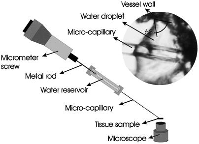
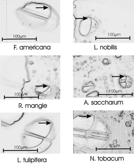
Contact angles were measured on freshly collected branches (1–2 cm in diameter). A thick (approximately 200-μm) cross-section was viewed using an inverted microscope. Water droplets were placed on the inner surface of individual xylem vessels using a fine (tip diameter approximately 5-μm) glass microcapillary (Fig. 2) whose outer surface had been coated with a thin layer of petroleum jelly. Because the vessel wall was not highly wettable, we were able to slowly expand and contract the water droplet. Droplets were photographed during steady-state conditions (i.e. the droplet was neither expanding nor receding). To improve our ability to resolve the contact angle, we superimposed an image of the droplet within the vessel over an image of the vessel after the droplet had been retracted into the microcapillary (Fig. 3). The focus was not altered between images. The contact angle was determined by measuring the angle between the tangent to the air-water interface and the vessel wall.
Figure 2.
Diagram of experimental set-up used to determine water-xylem wall contact angle showing inverted microscope, branch cross-section (tissue sample), and microcapillary tube used to place a water droplet on the inner surface of an individual xylem vessel (inset).
Figure 3.
Exemplar images (one per species) used in determining contact angle. Each frame shows the superposition of the vessel with water droplet in place over the same image after the droplet had been retracted into the capillary tube such that the outline of the vessel wall was more distinct. The focus was not altered between images. Arrows mark the point at which the contact angle was measured.
Intervessel Pit Geometry
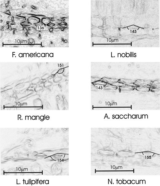
The structure of intervessel pits was determined from freehand longitudinal sections viewed in bright field (1,000× magnification, oil immersion) and photographed. Image contrast was enhanced using the “find edges” feature of the image process program Corel Photo-Paint (Corel, Ottawa, ON, Canada). The angle of the flared opening into the pit chamber was determined by drawing the tangent to the wall surface on both sides of the pit channel (Fig. 4).
Figure 4.
Exemplar images (one per species) used in determining the angle of the pit chamber (2α). Freehand cross sections were photographed using a compound microscope (1,000× magnification, oil immersion). Image contrast was enhanced using the “find edges” feature of the image process program (Corel Photo-Paint), which in effect, transforms the image into a topographic map. Tangent lines were drawn along the walls of the pit chamber and the angle of their intersection measured.
ACKNOWLEDGMENTS
We wish to thank A.R. Cobb, T.S. Feild, P.J. Melcher, H.A. Stone, and M.V. Thompson for stimulating discussions on this topic.
Footnotes
This work was supported by grants from the U.S. Department of Agriculture (National Research Initiative Competitive Grants Program grant no. 98–35100–6081) and the Andrew W. Mellon Foundation.
LITERATURE CITED
- Barnett JR. Xylem Cell Development. Tunbridge Wells, Kent, UK: Castle House Publications; 1981. [Google Scholar]
- Butterfield BG, Meylan BA. Three-Dimensional Structure of Wood: An Ultrastructural Approach. London: Chapman & Hall; 1980. [Google Scholar]
- Canny MJ. Vessel contents during transpiration: embolism and refilling. Am J Bot. 1997;84:1223–1230. [PubMed] [Google Scholar]
- Chapman DC, Rand RH, Cooke JR. A hydrodynamic model of bordered pits in conifer tracheids. J Theor Biol. 1977;67:11–24. doi: 10.1016/0022-5193(77)90182-5. [DOI] [PubMed] [Google Scholar]
- Core HA, Côté WA, Day AC. Wood: Structure and Identification. Syracuse, NY: Syracuse University Press; 1976. [Google Scholar]
- Denny MW. Air and Water: The Biology and Physics of Life's Media. Princeton University Press; 1993. [Google Scholar]
- Esau K. Anatomy of Seed Plants. New York: John Wiley & Sons; 1977. [Google Scholar]
- Holbrook NM, Zwieniecki MA. Embolism repair and xylem tension: do we need a miracle? Plant Physiol. 1999;120:7–10. doi: 10.1104/pp.120.1.7. [DOI] [PMC free article] [PubMed] [Google Scholar]
- McCully ME, Huang CX, Ling LE. Daily embolism and refilling of xylem vessels in the roots of field-grown maize. New Phytol. 1998;138:327–342. doi: 10.1046/j.1469-8137.1998.00101.x. [DOI] [PubMed] [Google Scholar]
- Meylan BA, Butterfield BG. Pit membrane structure in the vesselless woods of Pseudowintera dandy (Winteraceae) IAWA Bull. 1982;3:167–175. [Google Scholar]
- Milburn JA. Cavitation. A review: past, present and future. In: Borghetti M, Grace J, Raschi A, editors. Water Transport in Plants under Climatic Stress. Cambridge, UK: Cambridge University Press; 1993. pp. 14–26. [Google Scholar]
- Nobel PS. Biophysical Plant Physiology and Ecology. W.H. New York: Freeman; 1983. [Google Scholar]
- Pate JS, Canny MJ. Quantification of vessel embolisms by direct observation: a comparison of two methods. New Phytol. 1999;141:33–44. [Google Scholar]
- Pickard WF. The ascent of sap in plants. Prog Biophys Mol Biol. 1981;37:181–229. [Google Scholar]
- Salleo S, LoGullo M, Depaoli D, Zippo M. Xylem recovery from cavitation-induced embolism in young plants of Laurus nobilis: a possible mechanism. New Phytol. 1996;132:47–56. doi: 10.1111/j.1469-8137.1996.tb04507.x. [DOI] [PubMed] [Google Scholar]
- Sarkanen KV, Ludwig CH. Lignins: Occurrence, Formation, Structure, and Reactions. New York: John Wiley & Sons; 1971. [Google Scholar]
- Schmid R. The fine structure of pits in hardwoods. In: Côté WA, editor. Cellular Ultrastructure of Woody Plants. New York: Syracuse University Press; 1965. pp. 291–304. [Google Scholar]
- Sperry J, Holbrook NM, Zimmermann MH, Tyree MT. Spring filling in xylem vessels in wild grapevine. Plant Physiol. 1987;83:414–417. doi: 10.1104/pp.83.2.414. [DOI] [PMC free article] [PubMed] [Google Scholar]
- Spjotvoll E, Stoline MR. An extension of the T-method of multiple comparison to include the cases with unequal sample sizes. J Am Stat Assoc. 1973;68:976–978. [Google Scholar]
- Tyree MT, Salleo S, Nardini A, LoGullo MA, Mosca R. Refilling of embolized vessels in young stems of laurel. Do we need a new paradigm? Plant Physiol. 1999;120:11–21. doi: 10.1104/pp.120.1.11. [DOI] [PMC free article] [PubMed] [Google Scholar]
- Tyree MT, Sperry JS. Vulnerability of xylem to cavitation and embolism. Annu Rev Plant Physiol Plant Mol Biol. 1989;40:19–38. [Google Scholar]
- Yang S, Tyree MT. A theoretical model of hydraulic conductivity recovery from embolism with comparison to experimental data on Acer saccharum. Plant Cell Environ. 1992;15:633–643. [Google Scholar]
- Zimmermann MH. Xylem Structure and the Ascent of Sap. Berlin: Springer-Verlag; 1983. [Google Scholar]
- Zwieniecki MA, Holbrook NM. Short term changes in xylem water conductivity in white ash, red maple, and sitka spruce. Plant Cell Environ. 1998;21:1173–1180. [Google Scholar]


