

Abstract
Zn–air batteries are becoming the promising power sources for portable and wearable electronic devices and hybrid/electric vehicles because of their high specific energy density and the low cost for next‐generation green and sustainable energy technologies. An air electrode integrated with an oxygen electrocatalyst is the most important component and inevitably determines the performance and cost of a Zn–air battery. This article presents exciting advances and challenges related to air electrodes and their relatives. After a brief introduction of the Zn–air battery, the architectures and oxygen electrocatalysts of air electrodes and relevant electrolytes are highlighted in primary and rechargeable types with different configurations, respectively. Moreover, the individual components and major issues of flexible Zn–air batteries are also highlighted, along with the strategies to enhance the battery performance. Finally, a perspective for design, preparation, and assembly of air electrodes is proposed for the future innovations of Zn–air batteries with high performance.
Keywords: air electrode, architecture, electrocatalyst, flexible device, Zn–air battery
1. Introduction
Recently, sustainable development became a hot topic and major concern of the modern society, especially due to the great pressure of serious environmental issues and increasing energy demands.1 Renewable energy including solar, wind, waves, and hydropower are being the promising alternatives to replace the traditional fossil fuels to achieve the goal of green, economical, and sustainable society.2 However, their power output varies significantly over seasons, climates, and locations, and often mismatches the energy demands, even poisons gridding power.3 The effective and feasible solution to address the mismatch is to exploit energy storage and conversion technologies, and they are becoming the top priorities of current research for the scientific community, commercial companies, and national governments.4 As one of the most promising electrochemical energy technologies, lithium (Li)‐ion batteries lead the market of energy storage, especially consumer batteries in electronics and power batteries in hybrid/electric vehicles and stationary power plants.5 However, the insufficient energy densities of rechargeable Li‐ion batteries (200–250 Wh kg−1) limit their further development and applications.6
Metal–air batteries, whose theoretical energy density is even a few times more than the best performing Li‐ion batteries, are therefore being considered as an attractive solution and received more and more interests recently.7 Metal–air battery generates electricity via the redox reaction between metal at anode and oxygen in the air at a porous cathode, similar to the principles of fuel cells.8 The open cell structure of cathode is the paramount feature of metal–air batteries, which allows the continuous supply of oxygen from air.9 This feature directly endows the preference, especially a much higher theoretical energy density.10 Besides, the open structure also endows metal–air batteries many superiorities such as compact, light‐weight, and cost‐effective as this cathode replace the heavy and expensive constituents employed in Li‐ion batteries.11
There are various metal–air batteries according to different metal species used at anode.12 Among them, Li–air (oxygen) and Zn–air batteries are the most promising ones.13, 14 By now, Li–air batteries are the most discussed but controversial because of their combination of extreme high theoretical specific energy density as 5200 Wh kg−1 (including oxygen) and hazard potential.15 The hazard potential comes from explosive reactivity of lithium with air or water and ignites the flammable organic electrolyte used in most cases.16 Another inevitable drawback is the high cost (≈60 USD lb−1) and limited lithium resource occurring only in special natural mineral deposits in Australia and Chile.17 All above shortcomings of Li–air batteries limit their practical commercialization on large‐scale due to theses safety and economic issues.
Since the innate safety arise from using aqueous, nonflammable electrolytes and abundant global assets of zinc ore (Zn is the 4th most abundant in the earth crust, which is about 300 times greater than that of lithium),18 Zn–air batteries hold powerful potentials as the alternative to Li–air batteries, although the theoretical specific energy density of 1084 Wh kg−1 (including oxygen) is less than that of Li–air batteries, but still four times higher than those of current Li‐ion batteries.19 Besides, other advantages such as low cost and cheap (≈0.9 USD lb−1), low equilibrium potential, flat discharge voltage, long service life and environmental‐friendly further strongly guarantee the flourishing development of Zn–air batteries for the huge market of energy demands.20 In Zn–air battery, the most significant and complicated part is the air electrode integrated with gas diffusion layer and oxygen electrocatalyst layer.21 It is also closely related to the performance and cost which are the most outstanding technical challenges addressed for the target markets.22 However, the architectures of air electrode and wettability of components are often overlooked, which directly leads to a terrible performance of the whole cell even in case of employing highly active oxygen electrocatalysts.
Several previous excellent papers have reviewed the progress in the materials and systems of metal–air batteries,23 especially Li–air batteries,24 but few in Zn–air batteries.25 Nevertheless, in light of the increased research interest on Zn–air batteries, reviewing of current advances and future challenges is becoming highly necessary and significant. In this review, we summarize the continuous developments of Zn–air batteries, especially the exciting evolution of air electrodes over the past decades. After a brief introduction of Zn–air battery, the operation principles and relevant electrolytes are demonstrated. Then, a detailed discussion on the air electrode related issues for both primary and rechargeable Zn–air batteries are presented respectively. After that, regarding the fast development and demands of flexible devices, the technical issues of flexible Zn–air batteries with respect to air electrode, electrolyte, and assembly technique are also sequentially discussed. Finally, we will propose the understanding and perspective of the current trends and future challenges of air electrodes to address the intensive demands of Zn–air batteries. We hope this review would offer valuable insights for scientists and engineers to promote continuous innovations and commercialization of Zn–air batteries with high performance.
2. Zn–Air Batteries
Zn–air battery was initially proposed in 1878, while the silver wire acted as the air electrode.26 Few years later, a real gas diffusion electrode consisting porous carbon black and nickel current collector was reported in a so‐called Walker–Wilkins battery. Since the 1930s, a primary Zn–air battery was commercialized and was further applied in the hearing aids in 1970s.27 Now, its application has spread to seismic telemetry, railroad signaling, navigational buoys, remote communications, even electric vehicles and power grid.28, 29 However, hybrid/electric vehicles and power backup often need rechargeable batteries rather than primary ones.30
The evolution of rechargeable Zn–air battery is still hindered by nonuniform deposition of Zn and particularly the slow rates of oxygen evolution reaction (OER) and oxygen reduction reaction (ORR) at air electrode.31 There are many kinds of research focusing on Zn–air batteries between around 1975 and 2000, but the slow progress and the appearance of Li‐ion batteries sapped researchers' enthusiasm at the end of the 20th century.32 While in the recent few years, many improvements and huge energy demands restrike great interests in rechargeable Zn–air batteries.33 A lot of companies, such as EOS Energy Storage, Fluidic Energy, and ZincNyx Energy Solutions also joined the investigation and did a lot of excellent works.32 Nonetheless, as one of the promising alternatives for energy conversion and storage technologies, rechargeable Zn–air battery is still in the early stage. Therefore, extensive researches focusing on Zn–air batteries with outstanding electrochemical performance are growing in the flexible and wearable electronic devices for consumer batteries and rechargeable cells for power sources.
2.1. Configuration of a Zn–Air Battery
Zn–air battery consists of metal Zn electrode, membrane separator and air electrode, which are packaged together with the electrolyte, as illustrated in Figure 1 . The electricity is generated by the redox reaction between metal Zn anode and air cathode.34 Different parts of battery should satisfy different requirements.35 The zinc electrode which determines the capacity of the battery, should have a high activity and capacity for efficient recharging, and sustain the capacity over several hundred charge/discharge cycles.36 The separator should have a low electronic conductivity but a high ionic conductivity.37 The electrolyte should be appropriately active to Zn electrode, and have favorable conductivity as well as an excellent capability to sufficiently contact with air electrode.38 This review will focus on the air electrode, electrolyte, which is closely related to the air electrode, will also be briefly illustrated. The detailed description and challenges about Zn electrodes28, 31, 39 and separators20, 40 can refer to other excellent reviews.
Figure 1.
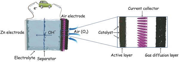
Schematic illustration of Zn–air battery and air electrode.
2.2. Electrolyte of a Zn–Air Battery
Zn can react violently in acidic solution and cause severe anode corrosion, thus in the most cases alkaline rather than acid electrolyte is often employed.41 The most widely used aqueous alkaline electrolytes for Zn–air batteries are potassium hydroxide (KOH) and sodium hydroxide (NaOH). While, KOH is usually preferred over NaOH, due to its higher solubility of zinc salts, higher oxygen diffusion coefficients, and lower viscosity.42 The ionic conductivity of K+ (73.50 Ω−1 cm2 equiv−1) is also better than Na+ (50.11 Ω−1 cm2 equiv−1).43 It was further demonstrated on the Pt electrode directly, ORR process prefers KOH rather than NaOH solution in both thermodynamic and kinetic consideration.44 The concentration of KOH solution should also be kept in contemplation. A higher alkaline concentration to some extent leads to a higher ionic conductivity45 but it results in an increased viscosity thus decreases the transfer rate of hydroxyl ions, while 30 wt% KOH solution has a maximum ionic conductivity at room temperature.46 In addition, the concentration of KOH electrolyte can directly influence the ORR activity of catalysts, which is related to oxygen solubility and oxygen diffusion coefficients.44 The concentration of oxygen (S) and KOH (C) satisfy the relation of logS = −2.9–0.1746C, while the diffusivity of oxygen drops sharply with the increase of KOH concentration.47 Employing Pt electrocatalyst, it is demonstrated that ORR performance indeed frustrates as the KOH concentration increases. Thus, 0.1 m KOH solution is widely used for ORR tests of electrocatalysts during the RDE measurements. However, for the assembly of Zn–air battery, a much higher concentration of KOH electrolyte (6 m) is often utilized to ensure a high ionic conductivity and suppress hydrogen gas generated at the surface of Zn metals.48 As the low solubility and diffusivity of oxygen in KOH electrolyte with high concentration, gaseous oxygen can be utilized much more efficiently than the dissolved oxygen during the full cell operation and three‐phase ORR is of greater significance in ambient air than in pure oxygen.48 It desires to be mentioned that, recently, some soluble zinc salts are also added to KOH electrolyte to increase the rechargeable performance of Zn–air batteries, such as zinc acetate49, 50 and zinc chloride.51, 52
Aprotic electrolytes, especially ionic liquids (ILs),53 may also be a promising alternative to the aqueous electrolyte according to their nonflammable nature, low volatility, high chemical, electrochemical stability, good thermal stability, and intrinsic ionic conductivity.54 For Zn–air batteries, their negligible volatility nullifies the “drying‐out” of electrolyte.55 Moreover, ILs can also support the reversible deposition and dissolution of Zn and would mitigate the formation of zinc dendrites thus can be used in the secondary zinc–air batteries.56 The replacement of aqueous electrolyte by some proper ILs can also affect the performance of electrocatalysts through a different interface of electrode–electrolyte.57 It is believed that nonreactive oxygenated species would be prevented from absorbing on the surface of electrocatalysts and maintain the fluent mass transfer of reactants at the same time.58 For ORR process, a proton source is required, and it can be abstracted from the cations of ionic liquids in some instances.59 Thus, for practice, proton given additives are often added. The onset potential of ORR for electrocatalyst can be significantly influenced by the proton activity of ILs with or without additives.60 Utilizing ILs with optimal proton additives, ORR process can also be facilitated from two‐electron reduction pathway to four‐electron pathway on Pt.61 However, aprotic electrolytes are currently in their initial stages and much work need to be done for Zn–air batteries. For example, most of the ILs can wet polytetrafluoroethylene (PTFE) and fill the electrode pores, although they are usually too viscous to entirely soak air electrode.39 Nevertheless, aprotic electrolytes still have worse electrocatalytic activities than potassium hydroxide electrolyte because of their higher ionic resistance and different electrocatalytic mechanism.62
3. Primary Zn–Air Batteries
3.1. Reaction Process of a Primary Zn–Air Battery
The reaction process of a primary Zn–air battery includes Zn oxidation reaction happened at anode and ORR at cathode.63 As a whole reaction for full cell, oxygen spreads into air electrode and then is reduced to hydroxyl ions at active catalyst layer, after that, the resultant hydroxyl ions migrate to anode and combine with zinc ions produced to form soluble zincate ions (Zn(OH)4 2−).64 When Zn(OH)4 2− reaches its saturation concentration, it will be decomposed to ZnO species.39, 65 The chemical reaction equations are listed below. Anode: Zn → Zn2+ + 2e−; Zn2+ + 4OH− → Zn(OH)4 2−; Zn(OH)4 2− → ZnO + H2O + 2OH−. Total: Zn + 2OH− → ZnO + H2O + 2e− (E 0 = −1.25 V). Cathode: O2 + 2H2O + 4e− → 4OH− (E 0 = 0.4 V). Overall reaction is 2Zn + O2 → 2ZnO (E 0 = 1.65 V). Here E 0 represents the standard electrode potential with respect to the standard hydrogen electrode.66 However, the practical working voltages are usually lower than 1.2 V, much less than standard potential (1.65 V) in consideration of the internal loss of battery, resulted from the activation, ohmic polarization and concentration loss.67
3.2. Air Electrode Architecture of a Primary Zn–Air Battery
Conventional air electrode is composed of three major components: current collector, gas diffusion layer, and active catalyst layer (Figure 1). The current collector is usually a conductive metal mesh, such as nickel foam68 and stainless steel.69 The gas diffusion layer, which is a channel for oxygen, should have a highly effective surface area which is preferable for the gas transfer and must be hydrophobic for the air contact while avoiding the leakage of electrolyte.70 The mixture of porous carbon materials and PTFE is often employed as the gas diffusion layer.71 The active layer is where ORR takes place and is crucial for the effective working of Zn–air batteries.72 In most cases, the active layer covers on the surface of current collector and contacts with electrolyte, while the gas diffusion layer lies on the reverse side and faces to the open air, and the current collector is placed in the middle of active layer and gas diffusion layer and then forms a sandwich structure.73 As oxygen has low solubility and diffusivity in most of the electrolytes, oxygen in the ORR process is mainly in the form of gas phase, thus boundary with a high‐surface area between triple active phases: gas (air), liquid (electrolyte), and solid (catalyst) is very crucial for an air electrode.74 That is why a dimensional porous architecture is favorable for air electrode.75
Except for gas diffusion layer, the active layer should also contain a porous substrate to supply enough space and react with oxygen at the surface of catalysts.76 Supporting materials are often employed to increase the utilization, enhance the activity and prolong the survival life of catalysts. Thus, high specific surface area, porous structure and abundant active side chain are needed to promote the good interaction of gaseous oxygen in electrolyte solution on the surface of catalysts.77 Moreover, the excellent conductivity, good stability, and corrosion/oxidation resistance are also important for supporting materials as the electron transfer happens during the long‐term harsh electrochemical process.25 Consequently, porous nanocarbons have also been demonstrated to be the most widely used supporting materials because of their distinctive physical and chemical advantages together abundant nature source and low‐cost manufacture.78 For example, graphene‐based composites have been applied in the catalyst layers.79 Furthermore, in order to make the catalysts tightly stick to carbon substrates, some polymer binders are also often introduced.80, 81
Since the crucial ORR mainly occurs at the triple phase zone (gaseous oxygen/solid electrocatalyst/liquid electrolyte),82 to meet the rigorous requirements of ORR, the excellent contact of oxygen and electrolyte on the surface of electrocatalyst is necessary and significant when constructing this triple phase boundary. While the wettability (hydrophobicity/hydrophilicity) of the components of air electrode with the electrolyte should be in charge of the sufficient contact.13 In addition, Zn–air batteries are very sensitive to the humidity of surrounding environment, the well‐balanced hydrophobicity/hydrophilicity can alleviate the evaporation loss and resist flooding of electrolyte.83 To realize the optimized wettability, the side contacting with electrolyte (active catalyst layer) should be hydrophilic, while the other side facing to air (gas diffusion layer) should be hydrophobic.84 The wettability of air electrode is often realized by the use of hydrophobic organic polymer particles such as PTFE,85 which is capable of water repellent properties and high chemical stability.86 PTFE is a synthetic fluoropolymer of tetrafluoroethylene and a kind of Teflon which is a registered trademark of DuPont company. The appearing of Teflon makes Zn–air batteries commercially feasible and allows oxygen electrode to operate efficiently.87 Actually, Teflon also contains other fluorinated ethylene propylene (FEP),88 but they are not so widely used in Zn–air batteries as PTFE.
An integrated air electrode for Zn–air battery is very complicated, hence, simple configurations are widely employed in the practical application.89 In a large proportion of cases, the diffusion layer is absent as porous carbon substrate in the active layer has a large specific surface area, which would effectively diffuse oxygen from the outer atmosphere into the cell.90 One typical method is to mix catalyst, porous carbon materials, polymer binder (PTFE) and press slurry onto a chosen current collector (nickel foam or other metal grids).91 In this design, PTFE is not only the hydrophobic coating but also a binder. The wettability of air electrode is determined by the proportion of carbon supports and PTFE used at different fabrication conditions. The proper PTFE content is 30–70 wt%,92 so that the active layer could be only partly wetted by the electrolyte.93 However, the different wettability of air electrode is of great importance, the absence of gas diffusion layer would inevitably affect the battery performance.
3.3. Oxygen Electrocatalysts of a Primary Zn–Air Battery
The operation of primary Zn–air batteries is deadly depends on ORR process at air cathode, thus the key component of air electrode is ORR electrocatalyst.94 However, the sluggish kinetics of ORR results in high overpotentials which would lower energy efficiency, and finally limit the output performance of primary batteries.95 Therefore, highly efficient ORR electrocatalysts are obligatory in the good operation of Zn–air batteries.96 The requirements of desired properties for efficient electrocatalysts include high active site density and uniform distribution for high ORR onset potential and high catalytic activity,97, 98 high surface area and sufficient porous structure for the sufficient mass transfer pathways99 and enhanced electrode kinetics,100 robust architecture for the chemical and mechanical stability for high durability, high mass and volumetric activities, and finally the abundant resource with low‐cost.101 However, most electrocatalysts are far from acceptability, thus the practical energy densities of existing Zn–air cells typically are far less and only 40–50% of the theoretical density.102
Basically, there are two standard ORR pathways takes place in alkaline solutions, direct four‐electron pathway (H2O) and indirect two‐electron pathway (H2O2).103 In the former, an oxygen molecule receives 4 electrons and is reduced to 4 OH− (O2 + 2H2O + 4e− → 4OH−, 0.4 V). In the latter, oxygen molecules are first reduced to intermediate H2O2, and through a further reduction to form OH− (O2 + H2O + 2e− → HO2 − + OH− (−0.07 V), HO2 − + H2O + 2e− → 3OH− (0.87 V)).104 Obviously, the 4‐electron mechanism is more efficient and favorable for Zn–air batteries, which would avoid the premature degradation of electrochemical cell caused by corrosion/oxidation of carbon supports and other materials by peroxide.105 Plentiful materials have appeared in the area of ORR electrocatalysts, including noble metals and their alloys, transitional metals, metal oxides/chalcogenides/carbides/nitrides, carbon nanomaterials, and their composites.106 However, different reaction mechanisms may happen on the surface of different catalysts.107 The 2‐electron reduction path is favored on most of nanocarbons108, 109, 110 and transitional metal based composites,48, 111, 112 while the direct 4‐electron reduction is favored on noble metal‐based catalysts.113, 114 Various ORR pathways exist on the transition‐metal based electrocatalysts, which depend on the molecular composition and specific crystal structures, even the experimental conditions.
Benefit from the similar principles, most of the oxygen catalysts employed in alkaline fuel cells and other alkaline metal–air batteries could also be served in Zn–air batteries.115 Noble metals and alloys,116 especially platinum (Pt),117 have been recognized as the most active electrocatalysts for ORR.118, 119 For example, PtCu nanocage was employed as an efficient ORR electrocatalyst for primary Zn–air battery.120 Alloying Pt with other appropriate metals even coupled with supporting materials can effectively improve the utilization and reduction of Pt usages,121 but the limited reserves, high price and poor stability of noble metals still hinders their widespread implementation in Zn–air batteries.122 Consequently, tremendous efforts are devoted to exploring, designing, and preparing nonprecious metal alternatives with high performance.123 For instance, MnO2 is frequently used as ORR catalysts.124, 125, 126 In Duracell hearing‐aid batteries, γ‐MnO2 was selected and this battery exhibited a very high energy densities of 400 Wh kg−1.39
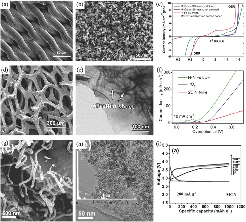
As mentioned above, carbon‐based materials are satisfactory supports. After heteroatoms doping (N, S, P, even transitional metal atoms), they also have potentials as the ORR electrocatalysts.127 The discovery of N‐doped carbon nanotube (CNT) as ORR catalyst inspires a boom of researches toward nanocarbon based electrocatalysts,128 their application in Zn–air batteries also spring up and much progress have been made.129 For example, Liang and his colleague reported a kind of hierarchical porous N‐doped carbon material with ultrahigh ORR catalytic activity even better than that of Pt/C (Figure 2 a).130 When assembled to Zn–air battery, this material behaved better than Pt/C especially at a high current density of 100 mA cm−2 (Figure 2b).130 Besides, N‐doped porous nanocarbons/graphene composite also exhibited a similar 4e ORR pathways as Pt/C (Figure 2c,d).131 Another battery sample assembled by N‐doped carbon nanofiber aerogel in Figure 2e has a specific capacity of ≈615 mA h gZn −1 at a discharged current density of 10 mA cm−2 (Figure 2f).132 The characteristic feature of carbon‐based catalysts is a high specific surface area, for instance, 1271 m2 g−1 for N‐doped carbon fiber (Figure 2g,h).133 Moreover, the doped porous carbon materials derived from metal–organic frameworks (MOFs) recently attracted progressive attention, benefiting from the abundant composition and excellent porous structure.134 For example, Chen and co‐workers employed Cu‐doped ZIF‐8 to synthesize Cu nanoparticles embedded in N‐doped mesoporous carbon polyhedron, the maximal power density of Zn–air battery assembled by this material was high to 132 mW cm−2.135
Figure 2.
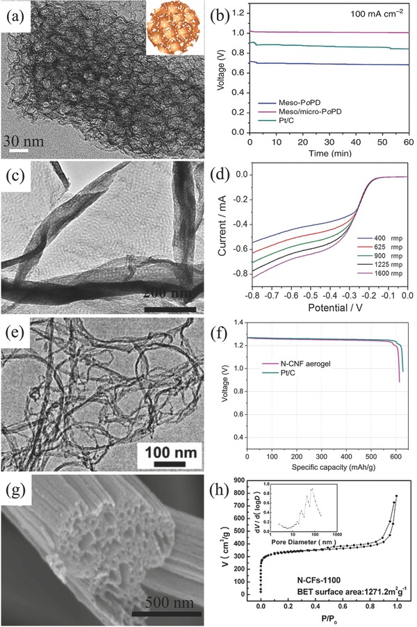
TEM image (a) and galvanostatic discharge curves of hierarchical N‐doped porous carbon (b). Reproduced with permission.130 Copyright 2014, Nature. TEM image (c) and RDE voltammograms (d) of nanoporous N‐doped carbon/graphene. Reproduced with permission.131 Copyright 2012, RSC. TEM image (e) and galvanostatic discharge curves (f) of Zn–air batteries with porous N‐doped carbon fiber. Reproduced with permission.132 Copyright 2015, Elsevier. SEM image g) and N2 sorption isotherm and pore size distribution h) of porous N‐doped fiber. Reproduced with permission.133 Copyright 2013, Elsevier.
Some current ORR electrocatalysts employed in Zn–air batteries have been summarized in Table 1 . It can be seen that noble metal‐based catalysts still exhibit a relatively better performance. However, the catalytic activity of non‐noble metal oxide catalysts can be enhanced by proper morphology, doping or cooperating with each other. Most nanocarbon‐based catalysts have the number of the electron transfer per oxygen molecule (n) lower than 4, but the lightweight and good conductivity can result in a relatively higher energy density. In this consideration, many researchers are focusing on cooperating different kinds of catalysts together to achieve the enhanced performance while lowering the cost of catalysts.
Table 1.
Summary of oxygen catalysts performed in primary Zn–air batteries
| Catalystsa) | ORR activity | Battery performancea) | Ref. |
|---|---|---|---|
| Cu‐Pt nanocage | Onset potential: 0.95 V; Tafel slope: 69.94 mV dec−1; n ≈ 4 | Specific capacity: 560 mA h gZn −1; energy density: 728 Wh kgZn −1 | 120 |
| Electrolytic MnO2 | – | Power density: 141.8 mW cm−2 | 107 |
| Ag4Bi2O5/MnO2 | n ≈ 3.7–3.8 | Discharge time: 225 h at 120 mA cm−2; power density: 250 mW cm−2 | 126 |
| 2D porous carbon | Onset potential: 0.930 V | Open‐circuit voltage: 1.48–1.52 V; specific capacity: 750 mA h g−1 | 108 |
| Graphene composite | n = 3.2–3.6 | Power density: 70 mW cm−2 | 131 |
| N‐microporous carbon | n = 3.0–3.7 | Discharge time: 3500 s at 50 mA cm−2 | 110 |
| N‐doped carbon fiber | n = 3.7–3.8 | Power densities: 194 mW cm−2 | 133 |
| N‐doped carbon nanofiber aerogel | Half‐wave: 0.80 V vs RHE; n = 3.97 | Specific capacity: ≈615 mA h g−1; gravimetric energy density: ≈760 Wh kg−1 at 10 mA cm−2 | 132 |
| N‐CNTs | n = 4 | Power density: 70 mW cm−2 | 76 |
| S/N‐carbon nanosheets | n = 3.96 | Power density: 252 mW cm−2 | 109 |
| Ag/C | n ≈ 3 | Power density: 34 mW cm−2 | 116 |
| Ag/CNCT | – | Specific energy density: 300 W h kg−1 | 160 |
| Pyrolyzed CoTMPP | n = 2.92 | Reach above 120 mA cm−2 at 1 V | 98 |
| Pyrolyzed FeCo‐EDA (FeCo‐N‐C) | Onset potential: −0.05 V vs SCE | Power density: 232 mW cm−2 | 97 |
| Graphitic carbon@CuFe | Tafel slope: 90 mV dec−1 | Power density: 212 mW cm−2 | 99 |
| Amide‐CoOx/C composite | Onset potential: ≈0.86 V vs RHE | Power density: 100–123 mW cm−2 | 112 |
| RGO–IL/Mn3O4 | n = 2.75 | Power density: 120 mW cm−2 | 112 |
| MnOx/Ketjblack | Onset potential: −0.05 V vs Hg/HgO | Power density: 190 mW cm−2 | 111 |
| Ni@MnOx/C | Onset potential: −0.177 V vs Hg/HgO; n = 3.83 | Power density: 122 mW cm−2 | 124 |
| α‐MnO2/XC‐72 | n = 3.8 | Power density: 61.5 mW cm−2 | 125 |
| MnxCo3− xO4/N‐Ketjen black carbon | n ≈ 4.1; Tafel slope ≈ 56 mV dec−1 | – | 48 |
| C‐PDA/Fe3O4 | Onset potential: −0.14 V | Stable discharge voltage for over 200 h | 100 |
The detail test condition refers to the primary references.
4. Rechargeable Zn–Air Batteries
4.1. Reactions in a Rechargeable Zn–Air Battery
For rechargeable Zn–air battery, discharge process is just like the primary ones, while charge process is reversible with discharge process.136 During the charge process, reactions happening at the cathode is the reduction of ZnO to metallic Zn, which is ZnO + H2O + 2OH− → Zn(OH)4 2− and followed by Zn(OH)4 2− + 2e− → Zn + 4OH−. Meanwhile, the oxidation of oxygen species (hydroxyl) to oxygen takes place at the anode, 2OH− → ½ O2 + H2O + 2e−. Thus, the overall reaction of charging is 2ZnO → 2Zn + O2. For primary Zn–air battery, ORR is the only functional reaction during the discharge process and key rate‐limiting step happened in the air electrode. While, for rechargeable ones, OER is another functional reaction for charging process.137 Thus, discharging and charging processes are promoted by the electrocatalytic ORR and OER, respectively.138
4.2. Configurations of a Rechargeable Zn–Air Battery
There are two types of rechargeable Zn–air batteries, mechanical and electrical.113 The prominent difference between them is that external recharging in mechanical ones by removing and replacing the discharged anodes or products such as zinc oxides and zincates, while the discharge/charge process takes place within the electrically rechargeable battery configuration.139 As the high cost of building the network for zinc recharging and supplying stations, mechanically rechargeable batteries are not widely used. In this critical review, we put emphasis on the electrical rechargeable Zn–air batteries.
For an electrically rechargeable Zn–air battery, the basic and most widely used configuration is the two‐electrode model.140 It is similar to primary Zn–air battery, while only the unifunctional ORR air‐cathode is replaced by a bifunctional electrode integrated with a bifunctional oxygen electrocatalyst or mixture of ORR and OER catalysts (Figure 3 a). Thus, oxygen electrochemical processes (ORR/OER) happen at the bifunctional air electrode during the discharging/charging processes respectively.141 However, it is theoretically in a short cycle life because ORR catalysts would be deactivated during the charging process at high voltages. In the discharging process, open circuit voltage of Zn–air battery is usually around 1.2 V. However, charging voltage needs to be raised to ≈2.0 V even higher due to the large overpotential of OER.39 The high potentials would cause the oxidation and corrosion of oxygen electrocatalysts. Moreover, porous structure is too fragile to suffer the gas generated (OER) in the charging process, which would result in the mechanical breakdown and catalyst loss of the electrode, followed by the death of battery.142
Figure 3.
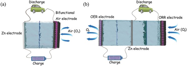
Schematic configurations of rechargeable Zn–air battery with two‐electrode (a) and trielectrode (b).
From the advantages of primary Zn–air battery and two‐electrode rechargeable Zn‐battery, a trielectrode configuration is then developed to solve this problem. The trielectrode configuration consists of two separated air electrodes corresponding to ORR and OER respectively, while Zn electrode is placed between ORR electrode and OER electrode (Figure 3b). ORR electrode connects with Zn electrode during discharging, while OER electrode is connected with Zn electrode during charging.143 Dai and co‐workers developed rechargeable Zn–air batteries in both two‐electrode and trielectrode configurations.142 CoO/carbon nanotube (CNT) hybrid and NiFe layered double hydroxide (LDH)/CNT composite were employed as ORR and OER catalyst, respectively (Figure 4 a–d). The air electrode was prepared by loading a simple mixture of ORR and OER catalyst on a Teflon‐treated carbon fiber paper with Nafion and was also paired with a Zn electrode in a two‐electrode system. The assembled battery demonstrated only a stable cycling performance when charging/discharging at low current densities (5–10 mA cm−2). However, the discharging overpotential of 200–250 mV after the second cycle was much obvious than the initial due to the partial oxidation and inactivation of oxygen electrocatalyst in the first charging process. When ORR and OER electrocatalysts were respectively loaded onto the separated ORR and OER electrodes, integrating with a porous Ni foam as current collector, the electrochemical properties of Zn–air battery in a trielectrode configuration was improved remarkably. Especially, the battery durability was improved respect to the two‐electrode configuration as it demonstrated a high cycling stability when repeatedly charged or discharged for a total of 200 h (20 h per cycle) at 20 mA cm−2. The overpotential increased was only 20 mV after 100 h operation in the case of anodically biased at 20 mA cm−2 (Figure 4e,f).
Figure 4.
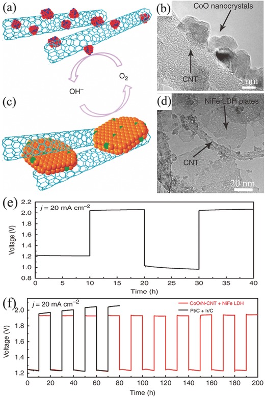
Schematic structure (a) and TEM image (b) of CoO/N‐CNT hybrid. Schematic structure (c) and TEM image (d) of NiFe LDH/CNT hybrid. Cycling performance for two‐electrode configuration (e) and trielectrode configuration (f) rechargeable Zn–air battery. Reproduced with permission.142 Copyright 2013, Nature.
Although the trielectrode configuration ensures a higher battery cycling stability than two‐electrode configuration, it unavoidably increases the volume and weight of batteries, thus reducing the volumetric energy as well as power density. Hence, the simple design of two‐electrode configuration is still more widely used. To overcome the drawbacks of two‐electrode configuration, a number of researches were devoted to preparing robust bifunctional oxygen electrocatalysts or bifunctional air electrodes. But until now, it is still a big challenge as most of the current bifunctional oxygen electrocatalysts exhibit uneven activity for ORR and OER, or limited stability, which will be reviewed in the following sections.144
4.3. Air Electrode for a Rechargeable Zn–Air Battery
Actually, air electrode determines the type and configuration of Zn–air battery, further the physical structure of air cathode seriously influence the final electrochemical performance of the battery. An air electrode optimally executes multiple functions including O2 diffusion, ion transport, electron transfer, electrocatalytic activity, and accommodate precipitate formation.39, 145 Thus, similar to primary ones, rechargeable Zn–air batteries also require high surface area to load and anchor oxygen electrocatalysts at catalytic active layer and appropriate pore channel for the efficient mass transfer and oxygen diffusion. As the role of oxygen electrocatalyst is to promote ORR and/or OER during the discharging–charging, and the electrochemical process happens just at the triple phase zone between liquid electrolyte and solid oxygen electrocatalysts/supports and gas oxygen reactant, the sufficient wettability of active catalyst layer allows the oxygen electrochemical reactions happen at the surface/interface of triple phase zone. Liu and co‐workers tuned the wettability of carbon nanotube arrays through adjusting the preparation process for efficient bifunctional electrocatalyst for Zn–air battery.146 Getting away the block of polymers, this approach demonstrated a better electrochemical performance. Moreover, the excellent interaction between electrocatalyst with substrate and the conductivity of whole electrode is also needed to meet the requirements for fast electron transfer and low interfacial resistance.
Compared to primary ones in practice, the significant change of air electrode in electrically rechargeable Zn–air batteries is that ORR electrocatalysts are transformed to bifunctional oxygen (OER/ORR) electrocatalysts, thus the same requirements as the primary batteries needed but not limited to these. OER happens during the charging of rechargeable Zn–air batteries, thus robust structure rather than fragile porous structure is more suitable for oxygen gas involved evolution reaction.143 Moreover, except the physical characters required, other properties like mechanical, thermal, electrochemical, and chemical stability are also very important to the stable operation of rechargeable batteries. The widely used carbon supports in ORR electrodes suffer from serious degradation under high potentials of OER process.147 It is reported that the potential only above 0.207 V can make carbon materials be thermodynamically corroded to carbon dioxide. This oxidation can become even obvious when a noticeable current density of oxygen evolution is often generated over 1.5 V, even RuO2 is employed.148 Thus, the anticorrosion/oxidization of carbon materials could be enhanced and utilized as low as possible in OER electrode.
Except the physical and chemical properties required in the electrode, the limited space in electronics and controlling on the weight is also significant to improve the quality and performance of batteries. These are obviously depending on the preparation techniques. The traditional fabrication via “brick‐and‐mortar” route requires the addition of many ancillary and inactive additives including polymeric binders and catalyst supports. These additives may not only contribute an excess weight to the final electrode (≈40%),149 but also compromises the electrochemical cell performance by the increased interfacial resistance caused by the insulating polymeric binders and the reduction of accessible active sites. The decomposition of additives during the reactions would also cause some catalysts fall off from the electrode surfaces.150 What's more, the additives such as PTFE may be oxidized and be failed over long operation times.151, 152 As a consequence, air electrodes with a minimized use of ancillary additives are serious in demand.
A characteristic binder‐free air electrode is made by the direct growth of carbon nanofiber arrays on an anodized aluminum oxide (AAO) substrate which is covered by thin layers of Ta and Fe. Fe layer served to catalyze the growth of carbon nanofiber arrays, while Ta layer is used as the conductive underlayer.153 However, AAO substrate is inactive. Consequently, the direct growth of oxygen electrocatalysts on the conductive current collector becomes the straightforward way to get an entirely binder‐free air electrode. In addition of binder‐free, this integration design can enhance the electron transfer between active layer and current collector. Furthermore, if metal materials are employed as the current collectors, the formed carbon‐free electrodes would also avoid the subsequent negative issues from carbon corrosion/oxidation at high potentials. For example, Jaramillo's group employed stainless steel (SS) as current collector and directly electrodeposited manganese oxide (MnOx) as oxygen electrocatalyst (Figure 5 a–c). The integrated MnOx/SS air electrode displayed an excellent oxygen electrocatalytic activity and stability toward ORR and OER, which was almost equal to MnOx and Ni catalysts deposited onto a carbon paper substrate.154 Qiao and co‐workers developed an in situ method to fabricate a multifunctional electrode consisting of N‐doped NiFe double layer hydroxides (LDH) on 3D Ni foam (Figure 5d–f). This integrated electrode demonstrated an outstanding OER catalytic activity and onset overpotential was only 0.21 V and thus was proposed as a good candidate for rechargeable Zn–air battery.155 Another example is a hybrid electrode of Ni foam supported carbon‐wrapped Mo2C nanoparticles/carbon nanotubes (Figure 5g–i). In this composite, porous carbon skeleton together with carbon nanotubes protruded from the composite forms a special 3D structure and gives a good access to oxygen gas evolution.156
Figure 5.
SEM images of bare (a) and MnOx deposited stainless steel mesh (b); linear sweep voltammogram (LSV) curves (c) of MnOx deposited stainless steel mesh. Reproduced with permission.154 Copyright 2014, RSC. SEM (d) and TEM (e) images, LSV plots (f) of OER catalytic properties of N‐NiFe LDH. Reproduced with permission.155 Copyright 2015, Wiley. SEM (g), TEM (h) images, and cycle performance (i) of MCN at current density of 200 mA g−1. Reproduced with permission.156 Copyright 2016, Wiley.
Actually, metallic mesh current collector still contributes a large proportion of the weight of traditional air electrode. Graphitic carbons such as carbon paper and carbon cloth as current collectors can dramatically reduce the weight of electrodes, thus they are widely applied to other energy devices such as Li‐ion batteries,157 supercapacitors,158 and Li–S batteries.159 Combination with nanotechnology, engineering graphitic carbon materials with active materials in free‐standing and porous structure is promising to maximize the utilization of current collectors.160, 161, 162 For example, a binder‐free air electrode made by Co3O4 nanoparticles decorated on carbon nanofiber mat was developed by thermally treating electrospun Co(II)‐containing polyacrylonitrile fibers, without any further modifications (Figure 6 a,b).163 The integrated Zn–air battery exhibited a small discharge/charge potential gap of 0.7 V at 2 mA cm−2, and the power density achieved 125 mW cm−2 (Figure 6c), which was ≈4 times higher than that of Zn–air battery equipped by the corresponding conventional air electrode (29 mW cm−2). Moreover, this battery also exhibited a better stability and cycling performance compared to battery assembled with Pt/C based air‐cathode. With the introduction of N‐doped graphitic carbon materials as ORR and/or OER electrocatalysts, the structure of air electrode can be further simplified. Peng and co‐workers developed a kind of carbon nanotube sheets as air electrode for flexible and stretchable fiber‐shaped Zn–air battery, in which CNT/RuO2 composites simultaneously worked as gas diffusion layer, catalyst layer, and current collector at the same time (Figure 6d,e).164 This assembled battery exhibited an enhanced discharge voltage plateaus especially at high current densities. Employing this simple air electrode, flexible fiber‐shaped Zn–air battery can be discharged/charged at 1.0 V at a high current density of 1 A g−1 (Figure 6f). After this, this design approach was further employed to assemble flexible Al–air batteries in a fiber‐shaped.165 Besides, the free‐standing graphene‐based composites could be used as air electrode if integrated with conductive Ag nanowires. For example, Zn–air battery employed this 3D graphene/Ag nanowires cathode can permit an ultrahigh discharge rate of up to 300 mA cm−2.166
Figure 6.
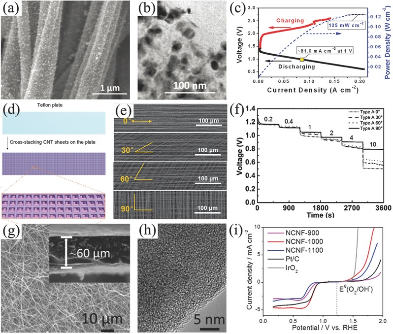
SEM (a), TEM (b) images, and battery performance (c) of C‐CoPAN900 mat based Zn–air battery. Reproduced with permission.163 Copyright 2015, RSC. Schematic preparation of CNT sheet based air electrode (d), SEM images of CNT sheets with different cross‐stacking angles of 0°, 30°, 60°, and 90° (e), rate discharge curves of flexible Zn–air batteries with different cross‐stacking angles of 0°, 30°, 60°, and 90° at different current densities (f). Reproduced with permission.164 Copyright 2015, Wiley. SEM (g), TEM (h) image, and oxygen catalytic properties of NCNF‐1000 (5 mV s−1) (i). Reproduced with permission.167 Copyright 2016, Wiley.
Obviously, doped‐ or modified‐graphitic carbon materials with porous structure can be as diffusion layers and electrocatalyst supports, high electrochemical performance can be as bifunctional oxygen electrocatalyst and good electrical conductivity can be as current collector, thus they have great potentials as the alternative air electrode simultaneously and further simplify from three components to only one part even one material if it can also be 3D and self‐standing. Liu and co‐workers prepared nanoporous N‐doped carbon nanofiber films after a thermal treatment of electrospun polyimide film (Figure 6g,h). This free‐standing film demonstrated many advantages including high specific surface area of 1249 m2 g−1, electrical conductivity of 147 S m−1, moderate tensile strength of 1.89 MPa and tensile modulus of 0.31 GPa. Importantly, this film also had a bifunctional catalytic activity for ORR (onset potential of 0.97 V and current density of 4.7 mA cm−2) and OER (onset potential of 1.43 V and potential of 1.84 V to achieve 10 mA cm−2, Figure 6i).167 Based on this extraordinary film, air electrode can be simply applied on primary liquid Zn–air battery, rechargeable liquid Zn–air battery and flexible all‐solid‐state rechargeable Zn–air battery, respectively. However, this kind of simple air electrode is very scarce. Although vertically aligned carbon nanotubes (VACNT)/graphene paper,168 3D VACNT‐graphene architectures,169 all carbon nanotube ultrathin films,170 and free‐standing CNT/graphene film are all realized,171 few of them are investigated in the area of rechargeable Zn–air batteries. In addition, nanocarbons such as graphene and CNT are proved either hydrophobic or hydrophilic.172 And the wettability of nanocarbons in the simplified air electrodes has been seldom discussed in practical operation. Thus, it would be proposed as a new promising method to promote the properties of this simple air electrode, and there is still enormous space for improvements in the electrochemical properties of Zn–air batteries in the aspects of integrated air electrode.
4.4. Oxygen Electrocatalyst for a Rechargeable Zn–Air Battery
Highly active and robust oxygen electrocatalysts are crucial for power, energy densities and energy efficiencies of Zn–air batteries,173, 174 and they are mostly focused on to develop high‐performance rechargeable Zn–air batteries.175, 176 However, ORR and OER process are so different that it is extremely difficult for one catalyst to satisfy the request for both oxygen electrochemical reactions.177 For Pt catalyst example, the equimolar ratio of primary oxide (Pt—OH) and surface oxide (Pt=O) is critical to ORR, but the formation of irreversible Pt=O decrease its catalytic activity toward OER.178 Oppositely, IrO2, RuO2 are effective for OER but not as active for ORR.179 Although nanotechnologies and nanomaterials remarkably increase the catalytic activity and reduce the usage of precious metals involved,180, 181 they are still limited due to the scarce assets and high cost,182, 183, 184 thus huge economic motivation and extensive scientific interests stimulate the exploration of cheap and earth‐abundant non‐noble metal alternatives to promote further development and commercialization of Zn–air batteries.119, 185, 186
In consideration to the advantages of tri‐electrode configuration in both separated ORR and OER electrodes, employing the same carbon electrocatalysts in the tri‐electrode configuration leads to a better cycle performance than the corresponding two‐electrode configurations.187 For example, primary battery assembled by N,P co‐doped carbon foam demonstrated an open‐circuit potential of 1.48 V and energy density of 835 Wh kgZn −1 (Figure 7 a,b).188 When assembled to rechargeable batteries in the form of tri‐electrode configuration, the cell demonstrated an excellent stability of 600 charge/discharge cycles for 100 h (Figure 7d), which was almost equal to that of Pt/C and RuO2 in tri‐electrode and better than same carbon electrocatalyst in the two‐electrode configuration of 180 cycles at 2 mA cm−2 (Figure 7c).
Figure 7.
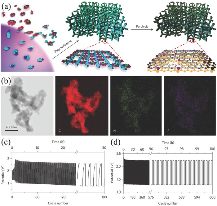
Schematic illustration of the synthesis method (a) and TEM images with corresponding element mapping (b) of N, P co‐doped mesoporous carbon foams. Cycling performance of rechargeable Zn–air batteries corresponding two‐electrode configuration (c), and trielectrode configuration (d) at current density of 2 mA cm−2. Reproduced with permission.188 Copyright 2015, Nature.
In spite of the capacity of the mixture of ORR and OER electrocatalyst employed in the air electrode, tremendous efforts have been devoted to developing bifunctional oxygen electrocatalysts.189 The most concerns about nonprecious oxygen electrocatalysts are transitional metal oxides such as spinel cobalt oxides (Co3O4).190, 191 However, most of them are of good OER catalytic activity but weak ORR catalytic activity.192, 193 For example, Manthiram and co‐workers employed Ni foam supported Co3O4 microtrepangs as OER catalyst but N‐doped carbons as ORR catalyst to assemble Zn–air battery.194 Zn–air battery exhibited a long cycle life of 200 cycles, and no significant changes in round‐trip overpotential after charge/discharge at 10 mA cm−2 for 800 h. Following nanomaterials engineering in doping and hybridizing with other functional nanocarbons, ORR activity of Co3O4 can also be enhanced recently. One typical example was 3D ordered mesoporous Co3O4 (3DOM Co3O4).195 Benefiting from the high active surface area and stable structure, this 3DOM Co3O4 was proved to be a promising candidate as bifunctional oxygen electrocatalyst (Figure 8 a–c). Combining with other active metal oxides such as MnO2 and/or coupling with carbon materials, the composites further demonstrated the enhanced catalytic activity for oxygen electrochemistry.196 For instance, Xu et al. used Co3O4/MnO2‐CNTs197 and La2O3/Co3O4/MnO2‐CNTs to assemble Zn–air batteries (Figure 8d–f).198 The voltage gap of charge/discharge increased only 0.1 V after 543 charge/discharge cycles at 10 mA cm−2 for the rechargeable Zn–air battery using Co3O4/MnO2‐CNTs catalysts.197 Other Co‐based bifunctional electrocatalysts even coupled with nanocarbons have also been investigated in Zn–air batteries, such as CoMn2O4/N‐rGO,199 MnCo mixed oxide,200 Co(II)1− xCo(0)x /3Mn(III)2 x /3S nanoparticles supported on B/N‐codoped mesoporous nanocarbon,201 Co‐PDA‐C,202 NiCo2O4,81 NiCo2O4/NCNT,203 Co‐doped TiO2,204 and CoSx@ N,S codoped graphene nanosheets.205
Figure 8.
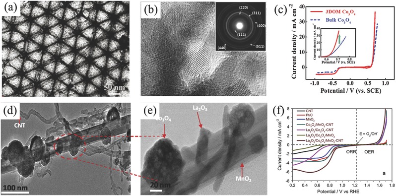
a,b) TEM images and c) oxygen electrochemical performance of 3D ordered mesoporous Co3O4. Reproduced with permission.195 Copyright 2016, Wiley. d,e) TEM images and f) corresponding ORR and OER polarization curves of La2O3/Co3O4/MnO2‐CNTs hybrid catalyst. Reproduced with permission.198 Copyright 2016, Elsevier.
Mixed metal oxides with perovskite structure are another kind of promising bifunctional oxygen electrocatalyst and have wide applications in Zn–air batteries.206, 207 The structure of them are in a general ABO3 formulation (A: rare earth or alkali metal ions; B: transition metal ions), in which the B site is usually recognized as catalytic active center. ORR and OER activities of perovskite oxides can be simultaneously improved by filling the surface B antibonding states of eg‐orbital close to 1 and can be further increased by enhancing the covalence of B—O bond.207, 208 For example, Cho and co‐workers optimized the size of Lax(Ba0.5Sr0.5)1− xCo0.8Fe0.2O3− δ nanoparticles to adjust the catalytic activity for ORR and OER at the same time.209 They claimed that the excellent catalytic activity for ORR (onset potential: 0.72 V) and OER (overpotentials at 2 A g−1: 1.54 V) can be simultaneously achieved by nanoparticles in the size of ≈50 nm (Figure 9 a–c). After 100 charging/discharging cycles, the overpotential difference between charge and discharge of this perovskite assembled Zn–air battery increased only 0.25 V (Figure 9d). In addition, PrBa0.5Sr0.5Co2− xFexO5+ δ (x = 0, 0.5, 1, 1.5, and 2) mesoporous nanofibers210 and La0.8Sr0.2Co1− xMnxO3 (x = 0, 0.2, 0.4, 0.6, 0.8, 1) nanostructures211 have also been reported. The electrocatalytic activity of these materials can be adjusted by the B‐site metal ratio, and the best performance can be achieved at x = 0.5 and 0.6, respectively. Besides, lanthanum based LaMO3 perovskite oxide is widely investigated in the area of Zn–air batteries as well, such as doped La2NiO4,212 LaFeO3 nanostructures,213 and LaCoO3 fibers.190 When being assembled into rechargeable Zn–air batteries, both of them can exhibit good properties. Moreover, the synergistic effect of La2NiO4 nanoparticles and carbon nanotubes214 or nitrogen‐doped carbon215 was found and it can further enhance the performance of Zn–air battery.
Figure 9.
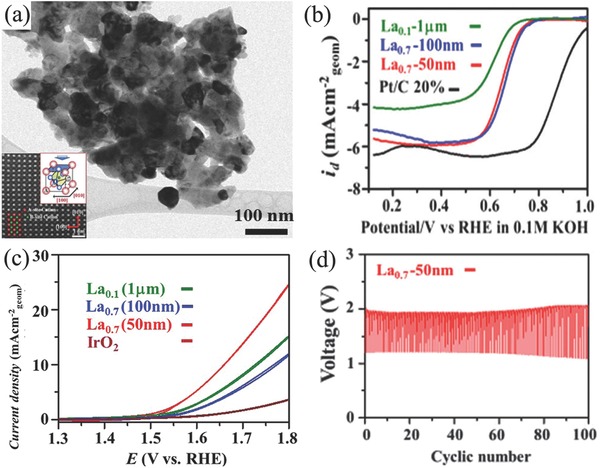
TEM image of Lax(Ba0.5Sr0.5)1− xCo0.8Fe0.2O3− δ (BSCF) nanoparticles with size of 50 nm (a); ORR (b) and OER (c) catalytic activity for BSCF nanoparticles; the repeated charge and discharge tests of BSCF nanoparticles based Zn–air battery (d). Reproduced with permission.209 Copyright 2016, RSC.
After the discovery of doped carbon materials in ORR application, nanocarbons were further found to exhibit OER activity individually or simultaneously.216, 217 Then cheap, highly reserved and safe carbon‐based materials were further investigated as oxygen electrocatalysts in the area of rechargeable Zn–air batteries.218, 219 Although the main concerns of carbon oxidation and corrosion at high potentials for most of carbon‐based catalysts studied,147 graphitic carbons,220, 221 and diamond carbons still display the great advantages of higher resistance to electrochemical oxidation and corrosion.222 For example, Zn–air battery used N,B codoped diamond as bifunctional oxygen electrocatalyst showed a power density of 24.8 mW cm−2 and a good stability of 80 cycles at a charge/discharge current density of 16 mA cm−2 (Figure 10 a,b).223 Another sample is microporous carbon sheets synthesized from eggplant, which exhibited a specific capacity of ≈669 mA h gZn −1 and was stably charged and discharged for 160 h at 2 mA cm−2 (Figure 10c,d).224 Both of them demonstrated excellent cycle performance and a long operation time without significant corrosion of carbon electrocatalyst during the charge/discharge process. With further structure optimizing, porous nanocarbons with high surface area such as hollow N‐doped carbon spheres were also employed as the electrocatalyst for Zn–air battery (Figure 10e).225 The potential gap of this assembled Zn–air battery increased just 40 mV after charge/discharge at 2 mA cm−2 for 5 h (Figure 10f). The similar method was also employed to prepare N,S‐codoped hierarchically porous carbon material as bifunctional oxygen electrocatalyst (Figure 10g,h).226
Figure 10.
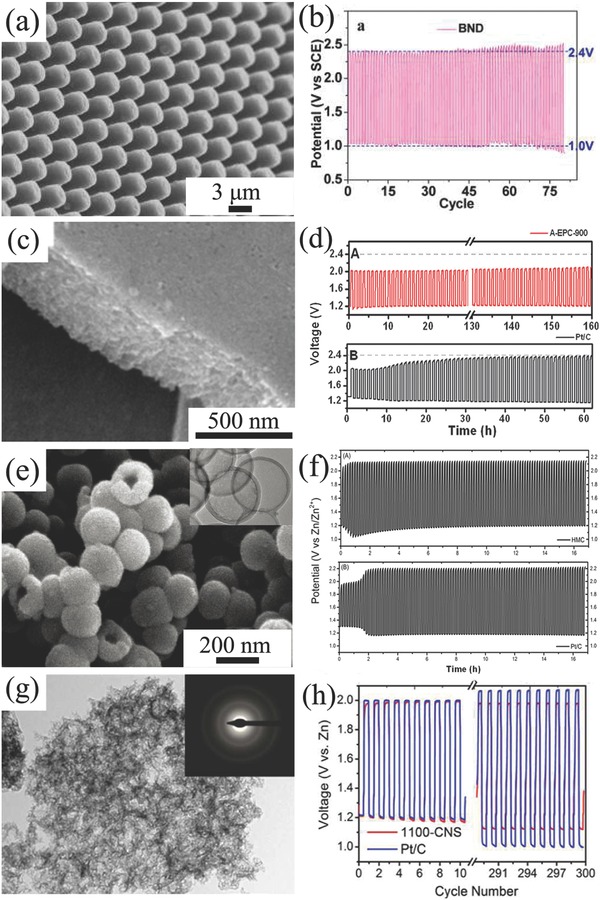
a) SEM image and b) discharge/charge cycling curve of Zn–air battery assembled by B, N‐codoped nanodiamond at 16.0 mA cm−2. Reproduced with permission.223 Copyright 2013, ACS. c) SEM image and d) discharge/charge cycling results of microporous carbon sheets and Pt/C based Zn–air batteries at 2 mA cm−2. Reproduced with permission.224 Copyright 2015, RSC. e) SEM and TEM images and f) corresponding discharge/charge cycling curves of hollow mesoporous carbon and Pt/C based Zn–air batteries at 2 mA cm−2. Reproduced with permission.225 Copyright 2015, RSC. g) TEM image and h) discharge/charge cycling curves of hierarchically porous carbon and Pt/C based Zn–air batteries at 10 mA cm−2. Reproduced with permission.226 Copyright 2017, RSC.
As containing atomically dispersed metal species and abundant nitrogen/carbon source, metal–organic frameworks (MOFs) is also an important platform material in the area of bifunctional oxygen electrocatalysts and rechargeable Zn–air batteries.227 For example, Liu et al. used Zn‐doped ZIF‐67 to acquire bifunctional oxygen catalyst.228 The Zn–air battery employed this catalyst can exhibit a high gravimetric energy density (889 Wh gZn −1), but the cycling performance was not that well as a stable charge/discharge for 33 h at current density of 7 mA cm−1. Zhao et al. directly heated the MC‐BIF‐1S and obtained N,B‐doped carbon material as a bifunctional catalyst for rechargeable Zn–air battery.229 This battery showed an excellent cycle performance as charge/discharge for 100 h at current density of 2 mA cm−1 without obvious performance loss. Zhao and co‐workers carbonized ZIF composite and obtained double shelled carbon nanocages (Figure 11 a).230 This novel structure showed a similar ORR (half‐wave potential: 0.79 V) and better OER (Ej = 10: 1.64 V) catalytic activity than both ZIF‐8 (ORR half‐wave potential: 0.73 V; OER Ej = 10: 1.70 V) and ZIF‐67 (ORR half‐wave potential: 0.8 V; OER Ej = 10: 1.68 V) derived carbon materials (Figure 11b). The optimized porous structures for MOF‐derived catalyst also promote the electrochemical properties, such as the template method to create dimensional porous structures.231 Chen et al. utilized 3D ordered SiO2 microspheres as template and prepared N‐doping porous carbon material with 3D photonic crystal architecture (Figure 11c).232 This 3D structure showed a fantastic surface area value of 2546 m2 g−1, when used to Zn–air battery, this battery exhibited an ultrahigh capacity (770 mA h gZn −1) as shown in Figure 11d. Ahn et al. assumed tellurium (Te) nanotube as template and covered it with ZIF‐8 and Fe‐PDA.233 After thermolysis and removal of Te, Zn, and Fe, N‐doped porous carbon nanotubes embedded with FeNxC active sites were formed (Figure 11e). The 1D porous structure of carbon nanotubes and FeNxC active sites would induce synergistic effects and guaranteed the excellent ORR and OER catalytic activity especially ORR catalytic activity. As shown in Figure 11f, it exhibited a better potential of 0.957 V at j = 0.3 mA cm−2 and E half of 0.867 V than unmodified porous carbon nanotubes. Song et al. grew MOFs on the surface of ZnO microspheres template and prepared hollow Co–N‐doped carbon materials.234 Zn–air batteries using this material acquired an excellent open circuit potential of 1.59 V and a high‐power density of 331.0 mW cm−2. Besides, rechargeable Zn–air battery assembled by ZIF‐selenized Co0.85Se nanocrystal showed a narrow discharge/charge voltage gap (0.8 V) and stable cycling performance (180 h) at current density of 10 mA cm−2.235 Hybridizing with other functional materials such as graphene,236 Mxene,237 and metal oxides,238 MOFs‐derived nanocomposites further demonstrated better oxygen electrochemical performance.
Figure 11.
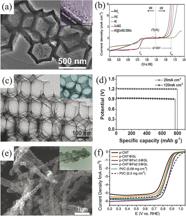
a) TEM image and b) OER and ORR polarization curves of double shelled carbon material derived from ZIF‐67@ZIF‐8. Reproduced with permission.230 Copyright 2017, Wiley. SEM image (c) and specific capacity of Zn–air battery employed photonic crystal architecture carbon (d). Reproduced with permission.232 Copyright 2017, Wiley. SEM image (e) and ORR performance of Fe–N‐porous carbon nanotubes covered with graphitic layer (f). Reproduced with permission.233 Copyright 2017, Wiley.
Table 2 summarizes some advanced oxygen electrocatalysts performed in rechargeable Zn–air batteries. According to this table, Co3O4 based nanomaterial is the most used among those potential bifunctional oxygen electrocatalysts. In addition, most of them exhibit good OER catalytic activity. This phenomenon is also present for mixed metal oxides with perovskite structure. In the opposite, carbon based materials prefer ORR activity rather than OER activity. Moreover, MOFs derived porous materials possess much bigger specific surface area which is beneficial for the three‐phase boundary reaction in Zn–air batteries. Thus, the suitable electrocatalysts or composites can be selected according to different requirements of batteries.
Table 2.
Summary of bifunctional catalysts performed in rechargeable Zn–air batteries
| Catalysta) | ORR activity | Test condition | OER activity | Battery performancea) | Electrolyte | Ref. |
|---|---|---|---|---|---|---|
| Pt/C (ORR); IrO2@Ti (OER) | – | 0.1 m H3PO4 + 1 m LiH2PO4 | Tafel slope: 121.8 mV dec−1 | Open‐circuit voltage: 2.1 V; cycling ability: 50 cycles (200 h) | LiOH‐H3PO4 + 1 m LiH2PO4 | 217 |
| Ni3FeN‐ordered Fe3Pt intermetallic nanoalloy | n = 4 | 0.1 m KOH | Overpotential 0.365 V at 10 mA cm−2 | Cycling ability: 480 cycles (40 h) @ 10 mA cm−2 | 6 m KOH | 173 |
| Atomically Pt‐CoO | Tafel slope: 43 mV dec−1 | 0.1 m KOH | – | Cycling ability: 30 cycles (charge @ 10 mA cm−2; discharge@ 5 mA cm−2) | 6 m KOH | 185 |
| Co3O4 | Onset potential: −0.197 V vs SCE; Tafel slope: 72 mV dec−1 | 0.1 m KOH | Tafel slope: 58 mV dec−1 | Power density: ≈73 mW cm−2; cycling ability: 200 cycles@10 mA cm−2 | 6 m KOH + 0.2 m Zn(Ac)2 | 195 |
| Co3O4 | Onset potential: 0.91 V | 0.1 m KOH | – | Cycling ability: 400 cycles @ 5 mA cm−2 | 6 m KOH | 191 |
| Co3O4 NW array/steel mesh | – | – | – | Cycling ability: 600 h @ 20 mA | 6 m KOH | 219 |
| LaCoO3 | Onset potential: −0.145 V; n = 3.43 | 0.5 m KOH | Onset potential: 0.693 V | – | – | 190 |
| La2NiO4 | Onset potential: 0.91 V vs RHE; n = 3.6–3.9 | 0.1 m KOH | – | Voltage gap: ≈1.51 V; cycling ability: 20 cycles (50 min) @ ≈25 mA cm−2, polarization increased 0.4 V at the end | 6 m KOH | 210 |
| Mn‐Co mixed oxide | Onset potential: 0.076 V; n = 3.34 | 0.1 m KOH | Overpotential: 0.246 V | Open circuit potential: 1.53 V; cycling ability: 60 cycles (30 h) @ 5 mA cm−2 | 6 m KOH | 200 |
| MnO2/Co3O4 | Onset potential: 1.05 V; Tafel slope: 58 mV dec−1 | 0.1 m KOH | Tafel slope: 34 mV dec−1 | Cycling ability: 60 cycles (7 h) @ 15 mA cm−2, polarization increased ≈0.3 V at the end | 6 m KOH | 192 |
| CoO nanoclusters and high‐index face Mn3O4 nano‐octahedrons | n = 3.8 | 0.1 m KOH | Overpotential: 378 mV | Cycling ability: 250 cycles @5 mA cm−2 | 6 m KOH | 193 |
| NiCo2O4 | Onset potential: 0.93 V vs RHE | 0.1 m KOH | Potential at 10 mA cm−2: 1.62 V; Tafel slope: 87 mV dec−1 | Open circuit potential: 1.45 V; Discharge capacity: 580 mA h g−1; cycling ability: 50 cycles (1000 min) @ 20 mA cm−2 | 6 m KOH | 81 |
| NiFeO@MnOx core–shell structures | n = 3.8; onset potential; 0.88 V | 0.1 m KOH | Tafel slope: 37–46 mV dec−1 | Cycling ability: 100 cycles @ 2 mA cm−2 | 6 m KOH | 176 |
| Pb2Ru2O6.5 | n = 4; onset potential: 0.89 V vs RHE | 0.1 m KOH | Tafel slope: 114.2 mV dec−1 | Cycling ability: 200 cycles (2000 min)@ 50 mA cm−2 | 6 m KOH | 175 |
| Nanocrystalline yttrium ruthenate pyrochlore | Onset potential: 0.85 V vs RHE; n = 3.8 | 0.1 m KOH | Overpotential: 1.45 V; Tafel slope: 112.4 mV dec−1 | Cycling ability: 200 cycles (2000 min) @10 mA cm−2 | 6 m KOH | 174 |
| Co‐doped TiO2 | Onset potential: −0.14 V vs Hg/HgO; n = 3.55–3.85 | 0.1 m KOH | Overpotential: 0.347 V vs Hg/HgO @ 10 mA cm−2 | Peak power density: 136 mW cm−2; cycling ability: 37 cycles (750 h) @ 20 mA cm−2 | 6 m KOH | 204 |
| Co3FeS1.5(OH)6 | Half wave‐potential: 0.721 V vs RHE; Tafel slope: 79 mV dec−1 | 0.1 m KOH | 1.588 V vs RHE @ 10 mA cm−2 | Specific capacity: 898 mA h g−1; Cycling ability: 108 cycles @ 2 mA cm−2 | 6 m KOH | 138 |
| NiMn LDH | – | 0.1 m KOH | Overpotential: 0.35 V; Tafel slope: 40 mV dec−1 | Cycling ability: 55 h @10 mA cm−2 | 6 m KOH + 0.2 m Zn(Ac)2 | 49 |
| Co5AlS1.5(OH)6 | – | – | Tafel slope: 79 mV dec−1 | Specific capacity: 898 mA h g−1; cycling ability: 108 cycles @2 mA cm−2 | 6 m KOH + 0.2 m Zn(Ac)2 | 138 |
| NiO/CoN porous nanowires | n = 3.97 | 0.1 m KOH | ΔE = 0.85 V | Open‐circuit: 1.46 V; power density; 79 mW cm−2 @ 200 mA cm−2; cycling ability: 50 cycles (500 min) @ 50 mA cm−2 | 6 m KOH | 182 |
| Ni3FeN | n = 3.79–3.87 | 0.1 m KOH | Tafel slope: 70 mV dec−1 | Cycling ability: 310 cycles (170 h) | 6 m KOH + 0.2 m ZnCl2 | 52 |
| Microporous carbon sheets | Onset potential: ≈69 mV vs Ag/AgCl; n ≈ 4 | 0.1 m KOH | Less positive onset potential than Pt/C | Discharge voltage: 1.23 V; cycling ability: 160 cycles (160 h) @ 2 mA cm−2 | 6 m KOH | 224 |
| Hollow N‐doped mesoporous carbon spheres | Onset potential: −0.055 V vs Hg/HgO; n ≈ 4 | 0.1 m KOH | Onset potential: 0.365 V vs Hg/HgO | Cycling ability: 30 cycles (5 h) @ 2 mA cm−2, polarization increased 0.04 V at the end | 6 m KOH | 225 |
| B‐N codoped porous carbon | Onset potential: 0.894 V; n = 3.6 | 0.1 m KOH | Onset potential: 1.38 V; Tafel slope: 201 mV dec−1 | Discharging voltage: 1.14 V; 52%; cycling ability: 600 cycles (100 h) @ 2 mA cm−2 | 6 m KOH | 229 |
| N,B‐doped diamond | Onset potential: −0.05 V vs SCE; n = 3.96 | 0.1 m KOH | – | Power density: 24.8 mW cm−2; cycling ability: 80 cycles @ 16 mA cm−2 | 6 m KOH | 219 |
| N,P‐doped carbon foam | Onset potential: 0.94 V vs RHE; half‐wave potential: 0.85 V vs RHE; n = 3.85 | 0.1 m KOH | – | Open‐circuit potential: 1.48 V; energy density: 835 Wh kgZn −1; power density: 55 mW cm−2; cycling ability: 180 cycles @ 2 mA cm−2 | 6 m KOH | 188 |
| N,S‐doped porous carbon | Onset potential: 0.99 V; half‐wave potential: 0.85 V; Tafel slope: 58 mV dec−1 | 0.1 m KOH | Tafel slope: 292 mV dec−1. | Power density: 151 mW cm−2; cycling ability: 55 h @ 10 mA cm−2 | 6 m KOH + 0.2 m Zn(Ac)2 | 226 |
| Single‐walled NCNTs/Ag | – | – | – | Open‐circuit voltages: ≈1.2 V; specific energy density: 300 Wh kg−1; specific capacity: 515 mA h g−1 | 6 m KOH | 160 |
| Co‐PDA‐C | Half‐wave: 767 mV vs RHE; n = 3.5–3.8 | 0.1 m KOH | 1.601 V (2 mA cm−2) | Cycling ability: 500 cycles @ 2 mA cm−2, polarization increased 0.23 V at the end | 6 m KOH | 202 |
| Co‐PDA‐N codoped carbon | n = 3.5–3.8 | 0.1 m KOH | Potential of 1.601 V is 45 mV less positive than that of Pt/C at 2 mA cm−2 | Cycling ability: 500 cycles (500 h)@ 2 mA cm−2 | 6 m KOH | 202 |
| MO‐Co@N‐carbon | n = 3.87 | 0.1 m KOH | Tafel slope: 77 mV dec−1 | Cycling ability: 385 cycles (3850 min) @ 10 mA cm−2 | 6 m KOH + ZnCl2 | 183 |
| C‐Fe‐UFR | Onset potential: 1.01 V; half‐wave: 0.86 V | 0.1 m KOH | Tafel slope: 160 mV dec−1 | Specific capacities: 467 mA h·gZn −1 @ 10 mA·cm−2; cycling ability: 100 cycles (2000) @ 10 mA cm−2 | 6 m KOH + 0.2 m Zn(Ac)2 | 269 |
| Ni3Fe/N‐carbon sheets | Onset potential: 0.90 V | 0.1 m KOH | Tafel slope: 77 mV dec−1 | Cycling ability: 105 cycles | 6 m KOH + 0.2 m ZnCl2 | 184 |
| Fe/Fe2O3@Fe‐N‐C | Onset potential: −0.04 V | 0.1 m KOH | Tafel slopes: 77.5 mV dec−1 | Open circuit voltage: 1.47 V vs Ag/AgCl; power density: 193 mW cm−2 @ 220 mA cm−2 | 6 m KOH | 93 |
| CoO/NCNT (ORR); NiFe‐LDH/CNT (OER) | Onset potential ≈20 mV negative to that of Pt/C | 6 m KOH | At 50 mA cm−2, ≈20 mV negative than Ir/C benchmarked | Power density: 256 mW cm−2; cycling ability: 20 cycles (200 h) @ 20 mA cm−2 | 6 m KOH | 142 |
| RuO2‐ordered mesoporous carbon nanofiber arrays | Half‐wave potential: 0.8 V | 0.1 m KOH | Tafel slope smaller than Pt/C | Cycling ability: 100 cycles (2000 min) @ 4 mA cm−2 | 6 m KOH | 180 |
| N‐doped carbon (ORR); Co3O4 @Ni(OER) | Half‐wave potential: 0.82 V vs RHE; n ≈ 4 | 0.1 m KOH | Tafel slope: 49 mV dec−1 | Voltaic efficiency: 64.5%; cycling ability: 200 cycles (800 h)@10 mA cm−2 | 6 m KOH | 194 |
| Co3O4/carbon nanofibers | Half‐wave: −0.188 V vs Ag/AgCl; n = 4 | 0.1 m KOH | Potential at 2 mA cm−2: 0.64 V vs Ag/AgCl; Tafel slope: 23 mV per decade | Power density: 125 mW cm−2; cycling ability: 135 cycles (135 h) @ 1 mA cm−2, polarization increased ≈0.08 V at the end | 6 m KOH | 163 |
| CoOx nanoarrays with porous N‐carbon | – | 0.1 m KOH | Δ E = 0.78 V | Cycling ability: 110 cycles | 6 m KOH + 0.2 m Zn(Ac)2 | 50 |
| Co3O4/MnO2‐CNTs | Onset potential: 0.958 V; Tafel slope: 113 mV dec−1 | 0.1 m KOH | Tafel slope: 61.5 mV dec−1 | Power density: 450 mW cm−2 | 6 m KOH | 197 |
| NCNT/CoxMn1− xO | Onset potential: 0.96 V; n = 3.8 | 1.0 m KOH | Tafel slope: 40 mV dec−1 | Gravimetric energy density: 695 W h kgZn −1; cycling ability: 12 h @ 7 mA cm−2 | 6 m KOH | 64 |
| CoMn2O4/N‐rGO | Onset potentials: 0.87 V vs RHE | 0.1 m KOH | OER of 10 mA cm−2 at 1.66 V | Charge/discharge voltage gap: 0.70 V; cycling ability: 100 cycles (500 min) @20 mA cm−2, polarization increased ≈0.2 V at the end | 6 m KOH | 199 |
| MnCo3O4/N‐carbon nanofiber arrays | Onset potential: 0.9 V vs RHE | 0.1 m KOH | Better than RuO2 | Cycling ability: 100 cycles (2000 min) @ 10 mA cm−2 | 6 m KOH + 0.2 m ZnCl2 | 51 |
| NiCo2O4/NCNT | Onset potential: 0.934 V; Tafel slope: 155 mV dec−1 | 0.1 m KOH | OER current density at 1.7 V is 16 mA cm−2 | Power density: 320 mW cm−2; voltage polarization: ≈0.75 V @ 10 mA cm−2; cycling ability: 60 h @ 10 mA cm−2 | 6 m KOH | 203 |
| MnO2‐NCNT | – | – | – | Cycling ability: 50 cycles (250 min) @ 8 mA cm−2, polarization increased ≈0.4 V at the end | 6 m KOH | 218 |
| La2O3/Co3O4/MnO2‐CNTs | Onset potential: 0.93 V; n = 3.9 | 0.1 m KOH | Onset potential: 1.42 V | Power density: 295 mW cm−2; cycling ability: 543 cycles (90.5 h) @ 10 mA cm−2, polarization increased 0.1 V at the end | 6 m KOH | 198 |
| LaNiO3/NCNT | Half‐wave potential: similar to commercial Pt/C. | – | – | Cycling ability: 75 cycles (375 min) @ 17.6 mA cm−2, polarization increased 0.1–0.2 V at the end | 6 m KOH | 220 |
| Atomically disperses Fe‐Nx/N, S‐hierarchical carbon layers | – | 0.1 m KOH | Tafel slope: 82 mV dec−1 | Power density: 102.7 mWcm−2;cycling ability: 100 cycles @ 5 mA cm−2 | 6 m KOH | 221 |
| Ni‐Fe nitride/N‐ graphene | Onset potential: 0.9 V vs RHE | 0.1 m KOH | Overpotential: 400 mV at 10 mA cm−2 | Cycling ability: 180 cycles (30 h) @ 10 mA cm−2 | 6 m KOH | 152 |
| Ni3FeN/Co, N‐CNF | Half‐wave potential: 0.81 V; Tafel slope: 52 mV dec−1 | 0.1 m KOH | Tafel slope: 51 mV dec−1 | Cycling ability: 540 h @ 6 mA cm−2; 136 h @ 50 mA cm−2 | 6 m KOH + 0.2 m Zn(Ac)2 | 151 |
| CoSx@ N,S codoped graphene nanosheets | Onset potential: −0.174 V); n = 3.2 | 0.1 m KOH | Onset potential: 0.674 V | Cycling ability: 50 cycles @ 1.25 mA cm−2 | 6 m KOH | 205 |
| Co(II)1– xCo(0)x /3Mn(III)2 x /3S/B/N‐Codoped mesoporous carbon | n ≈ 4 | 0.1 m KOH | Onset potential: 1.49 V vs RHE (1 m KOH); Tafel slope: 50 mV dec−1 | Power density: 250 mW cm−2; specific capacity: ≈550 mA h g−1; charge/discharge voltage gap: ≈0.72 V @ 20 mA cm−2 | 6 m KOH | 201 |
| NiCo2S4/N‐CNTs | n = 3.8 | 0.1 m KOH | ∆E = 0.80 V | Cycling ability: 150 cycles @10 mA cm−2 | 6 m KOH | 141 |
The detail test condition refers to the primary references.
5. Flexible Zn–Air Batteries
Except for the development of power battery, high market demands in consumer electronics especially portable and wearable devices also motive the new evolution of Zn–air batteries with some advanced features such as lightweight and shape conformability in the small unit.239 Therefore, developing suitable power supply system becomes imperative, Zn–air battery with flexibility and stretchability is then highly desirable.240 To successfully achieve this concept, flexibility of each component (cathode, anode, separator, and electrolyte) is the vital matter to obtain its stable battery performance during the repetitive external strain force.241 A summary of air electrodes and electrolytes employed in flexible Zn–air batteries could be seen in Table 3 .
Table 3.
Summary of flexible Zn–air batteries
| Anodea) | Electrolyte | Air electrode | Cell structure | Battery performancea) | Ref. | |
|---|---|---|---|---|---|---|
| Catalyst | Current collector | |||||
| Primary batteries | ||||||
| Spiral zinc plate | Gelatin‐0.1 m KOH | Fe/N/C | – | Cable‐type | Power densities: 217 mW cm−2 | 268 |
| Zinc powder | Polypropylene separator‐9 m KOH | Silver ink | Nano‐silver conductive ink on PP membrane | Sandwich structure | Energy density: 682 Wh kg−1 | 181 |
| Zinc foil | 6 m KOH | SWCNT | SWCNT | Sandwich structure | Discharge capacity: 375 mA h g−1 @ 0.25 mA | 264 |
| Recharge batteries | ||||||
| Zn spring | PVA‐PEO‐KOH | RuO2/CNT sheet | CNT sheet | Fiber‐shaped | Energy density: 6 Ah L−1; power density: 5.7 Wh L−1; cycling ability: 30 cycles @ 1A g−1 | 164 |
| Zn plate | PVA‐KOH gel | CuCo2O4/N‐CNTs | Carbon cloth and nickel foam | Cable‐type | Open‐circuit potential: 1.24 V; power density: 1.86 W g−1; cycling ability: 27 cycles (13.5 h) @ 0.5 A g−1 | 34 |
| Spring Zn belt | PVA‐KOH | Co4N/Co‐N‐C | Carbon fiber network | Cable‐type | Open‐circuit voltage: 1.346 V; cycling ability: 36 cycles (12 h) @ 0.5 mA cm−2 | 269 |
| Zn powder, carbon and polymer binder | Cellulose nanofibers | Co3O4 nanoparticles | Carbon cloth | Sandwich structure | Power density: 2362 mW g−1 @ 4650 mA g−1; cycling ability: 35 cycles (35 h) @ 250 mA g−1 | 255 |
| Zinc film | Laminate nanocellulose/GO/quaternary ammonium groups | Co3O4 | Carbon cloth | Sandwich structure | Open circuit voltage: 1.4 V; Power density: 44.1 mW cm−2; cycling ability: 30 cycles (10 h) @ 1 mA cm−2 | 256 |
| Zn on PET loading with Cu film | PVA‐KOH | Ultrathin Co3O4 layer | Carbon fibers | Sandwich structure | Cycling ability: 30 cycles (10 h) @ 2 mA cm−2 | 253 |
| Zn foil | PVA‐KOH gel polymer | Carbon nanofiber films | Carbon nanofiber films | Sandwich structure | Open‐circuit voltage: 1.48 V; peak power density: 185 mW cm−2; energy density: 776 Wh kg−1; cycling ability: 500 cycles @ 10 mA cm−2 (voltage gap increased ≈ 0.13 V) | 167 |
| Zn plate | PVA‐KOH gel | FeCo/N‐graphitic carbon nanotubes | Carbon cloth | Sandwich structure | Open‐circuit potential: 1.25 V; power density: 97.8 mW cm−2; cycling ability: 72 cycles (12 h) @ 100 mA cm−2 | 254 |
| Zn foil | Solid electrolyte | MnOx‐ Graphene coated carbon cloth | Ti mesh | Sandwich structure | Open‐circuit potential: 1.427 V; cycling ability: 145 cycles | 162 |
| Zn foil | PVA‐KOH | Co3O4/N‐CNT aerogel | N‐CNT aerogel | Sandwich structure | Open circuit voltage: 1.3 V; cycling ability: 20 cycles (20 h) @ 2 mA cm−2 | 240 |
| Zn film | Cellulose film | Co3O4/NCNT | Stainless‐steel mesh | Sandwich structure | Energy density: 847.6 Wh kg−1; cycling ability: 600 h @ 25 mA cm−2 | 245 |
| Zn film | PVA‐gelled electrolyte | LaNiO3/NCNT | Carbon cloth | Sandwich structure | Volumetric energy density: 2905 Wh L−1; gravimetric energy density: 581 Wh kg−1 @ 125 A L−1 (25 A kg−1); cycling ability: 120 cycles (40 h) @ 250 A L−1 (50 A kg−1) | 270 |
The detail test condition refers to the primary references.
5.1. Flexible Electrode
In the flexible Zn–air batteries, Zn anodes used are often in the foil, mesh, plate form, even a gelled mixture of zinc powders with some additives coating in a flexible current collector. While air electrodes should break through the disadvantages of tradition air electrodes such as heavy, rigid, and bulk configuration, thus flexible devices could be achieved, further excellent catalytic activity but yet good mechanical properties of air electrodes should be featured upon bending, folding, or twisting during the fabrication process.242
The most straightforward and effective method is to use flexible current collector, as the gas diffusion and catalytic layer can be grown, functionalized, anchored, and embedded onto the current collector to form a flexible battery. For example, Chen and co‐workers selected stainless steel mesh as current collector and directly grew Co3O4 nanowire array as flexible air electrode (Figure 12 a–c).243 This approach dramatically simplifies the design and fabrication procedure of flexible air electrode. Meanwhile, electrochemical activity and stability were also enhanced due to the nonconductive ancillary binding material and the reduced resistance due to the direct growth of catalyst on mesh collector. More importantly, the good mechanical strength of SS mesh ensures an excellent bending capability for battery device. Finally, the electrochemical performance of this advanced electrode is demonstrated to be better than Co3O4 nanowires and Pt/C sprayed on traditional gas diffusion layer based on carbon materials. The chemical coupling of Co3O4 nanostructures with graphene or mildly oxidized carbon nanotubes can exhibit much higher oxygen electroactivity than free Co3O4 nanostructures alone.244 Chen and co‐workers developed their carbon‐free air electrode, still choosing a flexible stainless‐steel mesh as current collector, but growing 2D mesoporous Co3O4 nanopetals in 1D N‐doped CNT as the catalyst layer.245 The intimate interfacial contact and interaction between Co3O4 nanopetals and conductive NCNT might provide opportunities to reduce the interface resistance and facilitate charge transfer, while the porous architecture nature of air cathode contributed to the efficient oxygen diffusion. By employing this air cathode and a free‐standing zinc film anode, the produced solid‐state Zn–air battery achieved a high energy density (847.6 Wh kg−1) and an outstanding cycling stability (600 h at 25 mA cm−2). Li et al. annealed Ni foam decorated with ZIF‐67 to prepare 3D NCNT arrays as air electrode (Figure 12d,e). Even under serious bending stress, flexible Zn–air battery assembled by this air cathode can yield a stable discharge potential of 1.02 V and charge potential of 1.98 V at 5 mA cm−2 (Figure 12f).246
Figure 12.
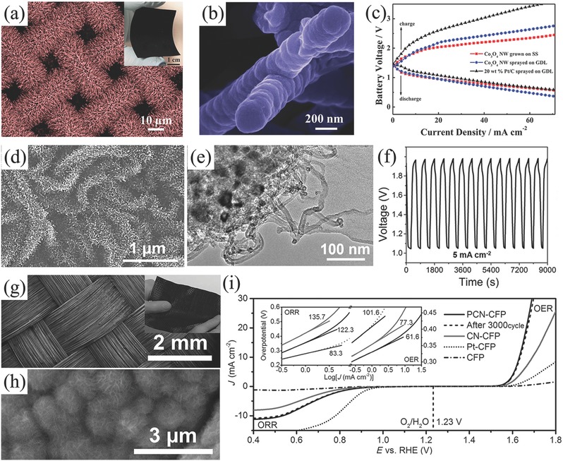
SEM images of SS mesh current collector coated with Co3O4 NW array (a,b); galvanodynamic discharge/charge curves obtained based on the Co3O4 NWs grown on SS mesh (c). Reproduced with permission.243 Copyright 2014, Wiley. SEM (d) and TEM (e) images of 3D NCNT arrays; galvanostatic discharge–charge curve of the flexible Zn–air battery utilized the 3D NCNT arrays (f). Reproduced with permission.246 Copyright 2017, Elsevier. SEM images of PCN‐CFP (g,h); LSV curve of PCN‐CFP at scan rate of 0.5 mV s−1 (i). Reproduced with permission.242 Copyright 2015, Wiley.
In view of high tensile strength and good conductivity of graphitic nanocarbon‐based materials such as CNT and graphene, flexible air electrodes can be realized by these carbon‐based current collectors.247 In addition, advantages of large availability and light weight for carbon materials could also reduce the weight of whole cell, resulting in a higher gravimetric capacity, which is the most imperative requirement for the portable/wearable electronics.248 Qiao and co‐workers reported the fabrication of flexible and reversible oxygen electrode of carbon‐fiber paper covered by phosphorus‐doped graphitic carbon nitrides (Figure 12g–i).242 Due to the robust porous 3D network with high conductivity, carbon‐fiber paper presented an excellent flexible current collector. Similar to carbon fibers current collector, other flexible carbon‐based candidates are also employed to replace the conventional metal current collectors.249
5.2. Electrolyte
As mentioned above, oxygen electrochemical reaction happened at the interface/surface of triple phase zone, thus the mutual contraction of electrolyte with oxygen dissolved on the surface of catalysts determines the efficiency of reaction.162 The good contact of electrolyte and catalysts is closely related to the wettability of air cathode. Except the modification/functionalization of catalysts and air electrodes, the properties of electrolytes can also determine the interaction of air electrodes and the diffusion of reaction materials and products.250 For flexible Zn–air batteries, liquid electrolytes may suffer from leakage problem during the repeated mechanical deformations, thus non‐liquid electrolytes are more favorable to serve as a species transport medium in Zn–air battery.28 Moreover, the advantages of polymer electrolytes such as film‐forming characteristics, high water solubility, sufficient mechanical strength, and conductivity offer desirable both physical and chemical properties. There are three kinds of polymer electrolytes often used in Zn–air batteries including gel polymer, solid polymer and composite polymer electrolytes.
Gel polymer itself is not an electrolyte but formed by incorporating liquid plasticizer and/or ionically conducting electrolyte solutions containing suitable solvents (KOH solution) and compounds into a polymer matrix.251 The high contains of electrolyte solution and diffusive transport property like liquid guarantee a better ambient ionic conductivity than their corresponding solid counterparts.252 However, the poor mechanical strength and high viscosity would probably cause an internal short circuit.253 In order to overcome this shortcoming, the gel electrolyte often cooperates with cross‐linkers to obtain a solid polymer electrolyte and thus enhance the mechanical properties.254 For example, Chen and co‐workers reported the enhanced electrolyte stability by self‐crosslinking among the dimethyloctadecyl [3‐(trimethoxysilyl) propyl] ammonium chloride functionalized cellulose nanofibers.255 Besides, they also developed a laminated cross‐linked nanocellulose/graphene oxide electrolyte for flexible rechargeable Zn–air battery.256
Contrary to gel polymer, solid polymer electrolyte has good mechanical strength and robustness, they were introduced in Zn–air batteries in 1990s.257 It is a liquid‐free system and composed by only salts and polar polymer matrix.258 Due to its solid nature, the problem of solvent evaporation and battery leakage could be alleviated even eliminated.259 And the low convection property would be beneficial for alleviating the electrode corrosion and increasing the battery life. Nevertheless, there is still much work to be done in the future excellent flexible Zn–air batteries due to the current relatively poor contact with air cathode and low ion conductivity.260 Composite polymer electrolytes are formed by adding inorganic materials or ionic liquids into the gel polymer electrolyte to obtain an enhanced conductivity and mechanical performance of gel electrolyte.261 In practice, the simplest and most used polymer electrolyte for Zn–air batteries is the mixture of KOH solutions and polymer hosts such as polyethylene oxide (PEO), poly vinyl alcohol (PVA), and poly acrylic acid (PAA).262 Actually, the single polymers cannot satisfy both needs of the mechanical and ion conductivity acquired simultaneously, the cooperation of both even triple hosts is often required to improve their ionic mobility.263
In the present flexible Zn–air batteries, all the employed electrolytes are gel polymer in consideration of conductivity and simple synthesis, although most of them are claimed to be all‐solid.264 As mentioned, this water enriched electrolyte is faced with poor mechanical property and water evaporation.265 What's more, even employing gel polymer, flexible battery is inclined to display a relatively poor electrochemical performance compared to liquid batteries because of the high ionic resistance of polymer electrolyte.266 Thus, real highly conducive and all‐solid‐state electrolytes are vital obligation and many efforts are being devoted to their discovery. We believe the real effective all‐solid flexible Zn–air batteries will be grasped in the nearby future.
5.3. Configurations of a Flexible Zn–Air Battery
There are two configurations for flexible Zn–air batteries. One is the cable‐type configuration, which is widely demonstrated in flexible Li‐ion cells and Li–air batteries (Figure 13 a).267 The cable‐type Zn–air battery usually has the structure of polymer electrolyte around the surface of central zinc belt, while the outside of polymer electrolyte is coated with flexible air electrode or directly with electrocatalysts. Cho and co‐workers first introduced the cable design into primary Zn–air battery.268 This battery was employed a spiral zinc as anode, a gel polymer based on gelatin as electrolyte and air electrode with catalyst made by annealing the mixture of iron acetylacetonate, silk fibroin and ketjenblack (Figure 13b,c). Bending tests exhibited no difference during the discharge process at 0.1 mA cm−2 under the bending and nonbending conditions. This result illustrated that cable‐type Zn–air batteries have the ability of efficient operation under the external strain. Liu and co‐workers also reported the similar cable battery with the use of novel Cu–Co bimetallic oxide quantum dots decorated NCNTs as electrocatalyst.34 The use of NCNTs substrate not only increased the conductivity of catalyst but also acquired a larger surface area, thus the as‐made flexible Zn–air battery exhibited a stable charging and discharging platforms of 1.29 and 0.98 V, respectively, at current density of 1 A g−1. Those charging/discharging potentials can still remain constant when the battery was folded or under serious twist. Zhang and co‐workers also reported the fabrication of flexible and rechargeable cable‐type Zn–air battery, where they employed a free‐standing bifunctional cathode composed of strung Co4N and intertwined N‐carbon fibers made by directly carbonization of ZIF‐67/polypyrrole nanofibers network on carbon cloth.269 Due to the intimate contact of electrocatalysts and carbon cloth, the assembled cable‐type Zn–air battery exhibited an excellent electrochemical performance and mechanical stability. Under bending stress (bent at 30°, 60°, 90°, and 120°), the discharge voltage at a current density of 0.5 mA cm−2 (≈1.23 V) and charge‐transfer resistances (≈17 Ω) remained almost unbothered. Even after bending/stretching of 2000 cycles, the discharge curve dropped only ≈13 mV.
Figure 13.
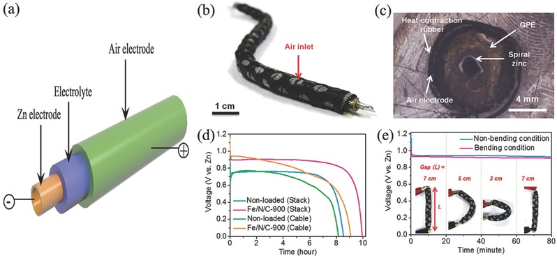
a) Schematic representation, b) photograph, c) cross‐sectional image, d) discharge curves of cable‐type and corresponding stack‐type Zn–air batteries with and without Fe/N/C electrocatalysts, respectively, and e) discharge curves of cable‐type Zn–air battery under bending strain every 20 min at discharge current density of 0.1 mA cm−2. Reproduced with permission.268 Copyright 2015, Wiley.
Another configuration type for flexible Zn–air batteries is sandwich structure, where anode, electrolyte and air cathode are in plan form and assembled layer by layer (Figure 14 a). Fu et al. reported the formation of air electrode through coating Co oxide and perovskite lanthanum nickel oxide/N‐CNT on the flexible carbon cloth substrate. The anode was zinc film, while the electrolyte and separator were gelled PVA membrane (Figure 14b).270 This flexible battery exhibited a high volumetric energy density of 2905 Wh L−1 and gravimetric energy density of 581 Wh kg−1, respectively. The cycling performance was also excellent and could be stable over 120 cycles under a charge/discharge rate of 250 A L−1 (50 A kg−1). The electrochemical performance was not weakened even at the harsh bending stress (Figure 14c). Zhang et al. assembled a flexible Zn–air battery by employing laminate‐structured nanocellulose/GO based membrane as a solid‐state electrolyte (58.8 mS cm−1 at 70 °C), accompanying with zinc film anode and carbon cloth coated Co3O4/Nafion air electrode (Figure 14d,e).256 This device afforded an obvious open‐circuit voltage of ≈1.4 V, and the battery performance remained virtually unchanged at any given bending angles, even at a high current density of 80 mA cm−2. Obviously, the intimate contact and strong interaction of robust solid‐state electrolyte layer with anode and air cathode is the main reason for this excellent battery performance under bending conditions. Ma and co‐workers also reported a sandwich structured flexible Zn–air battery which used FeCo/N‐CNT as the bifunctional electrocatalyst, and demonstrated an excellent cycling performance of 144 cycles even at a high current density of 100 mA cm−2.254
Figure 14.
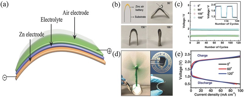
a) Schematic representation of sandwich structure flexible zinc–air battery configuration. b) Optical pictures of flexible zinc–air battery when applied stress to different angles; c) corresponding galvanostatic charge–discharge cycling performance at a current density of 250 A L−1 (50 A kg−1) under different degree of bending strains. Reproduced with permission.270 Copyright 2015, Wiley. d) Optical pictures of flexible zinc–air battery, and e) corresponding charge/discharge polarization curves of battery under bending stress to different angles. Reproduced with permission.256 Copyright 2016, Wiley.
To get better mechanical performance, a concept called “break up the whole into parts” strategy was developed for flexible Zn–air battery array recently.271 Zhong and co‐workers present a layer‐by‐layer assembly of 2 × 2 electrode arrays.272 The air electrode was composed of Co3O4 nanosheets in situ grown on carbon cloth (Figure 15 ). The battery array can present significantly stable output voltages even under tensile strains of 100%. But increasing elongation, the discharge voltage plateaus decrease slightly at high current densities. Obviously, besides the electrode and electrolyte, the assembly packing techniques also greatly affect the battery performance through the sufficient contact of each component. In the future, researches related to flexible Zn–air batteries would focus on not only the active electrocatalysts, but also the architectures of air electrode, the conductive electrolytes and the assembly techniques.
Figure 15.
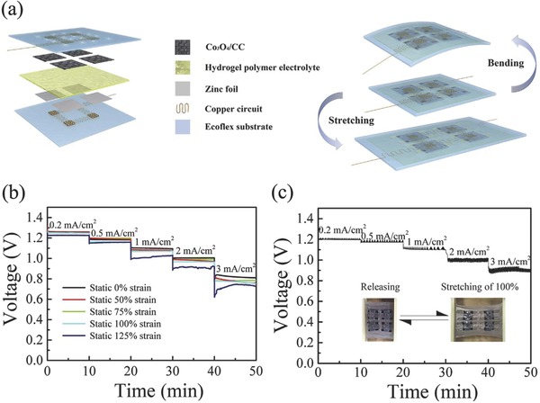
a) Structure illustration of flexible Zn–air battery, b) rate discharge performances of the array under different static strain of 0%, 50%, 75%,100%, and 125% at different current densities, and c) rate discharge performances of the array under dynamically stretching/releasing cycling of a maximum tensile strain of 100% and rate of 2 s per cycle. Reproduced with permission.272 Copyright 2017, Elsevier.
6. Conclusion and Outlook
Zn–air battery is one of the utmost potential energy technologies because of its high specific density and low cost, which would encounter the ever‐increasing energy demands for portable/wearable electronic devices and electric vehicles. Although considerable progresses have been made in recent years, there are still many problems need to be addressed. For power batteries in electric vehicles and power plants, the low practical energy density is the main hindrance, and consumer batteries also have to take into consideration the mechanical performance, safety and stability in flexible and portable devices. But all of these are closely related to air electrodes and their relevant components, including oxygen electrocatalysts, current collectors, and electrolytes. This review highlights their exciting advances and major issues in aspect of respective components. Thus, the intention of this review is to provide valuable understandings and insights for research community and application sectors to speed up innovation especially in air electrodes related parts for high performance Zn–air batteries.
Oxygen electrocatalyst is the key component in air electrode, which determines the configurations, performance, and cost of Zn–air batteries, thus the first emphasis of air electrode should be highly efficient and robust but cheap oxygen electrocatalysts. Noble metal catalysts exhibit extraordinary catalytic activity, but the inevitable degradation at high charge/discharge potentials in oxygen electrochemical reaction induce the poor cycle ability of battery. Meanwhile the disadvantages of cost and scarcity also limit the wide applications. Thus, progressive attention would be paid on the exploration and preparation of new non‐noble metal catalysts with high activity and improved durability, such as nanocarbons, metal oxides/carbides/nitrides, conductive polymers, metal coordination complexes, metal–organic frameworks, and their composites. By nanotechnologies and material engineering, the density of active sites and intrinsic catalytic capability of catalyst composites would be improved by selecting proper components, controlling morphologies and structures, tuning the physicochemical properties including valence, phases and defects, etc., and coupling with conductive supports/substrates. Moreover, rechargeable batteries need bifunctional ORR and OER catalysts relative to the unifunctional ORR in primary ones. Although three‐electrode configuration or the use of mixed ORR and OER electrocatalyst could provide alternative solutions, bifunctional ORR/OER catalysts are still becoming hot topic as they can provide ORR and OER activity simultaneously in the rechargeable batteries with two‐electrode configuration. Contrast to ORR process, OER process involves oxygen generation during the charging process, thus the optimized pore channels are required to quickly release oxygen bubbles formed on the surface of catalysts, otherwise the battery reaction will be gradually shut off with the resultant poor battery efficiency.
Although the ORR, OER, and bifunctional oxygen electrocatalysts have received great improvements and developed to a variety of species in the fuel cells and other metal–air batteries, the types of electrocatalysts are far from the practical application of Zn–air batteries. Benefiting from the development of oxygen catalysts in fuel cells, water splitting and metal–air batteries, but real, and full understandings of oxygen electrochemical behaviors should be further illuminated. This will be the second investigation emphasis on air electrodes, as different kinds of catalysts in both aqueous and nonaqueous electrolytes exhibit different reaction pathway and mechanisms. By means of advanced characterization techniques and combining high‐throughput calculations and simulations, the achieved molecular or even atomic level observation and understanding would engage the innovation of highly efficient oxygen electrocatalysts and air electrodes.
In the aspect of the substrate, that is another important element and plays the role of current collector and mechanical support to the battery devices, thus the porous structure, good mechanical strength and excellent conductivity should be taken into consideration simultaneously. Although metal current collector satisfies these requirements, for example, Ni foam, the price and weight limited their use to wide market. On the opposite, carbon‐based current collectors are cheap and light‐weight, however, it is too fragile and easy to be oxidized especially in the charging process. Thus, combining the advantages of metal and graphitic nanocarbons collectors will be one of the research emphasis on air electrode. Moreover, sufficient contact between catalyst and current collector must be adequate to ensure easy electron transfer across the interfaces. Directly growing electrocatalysts on current collectors and making binder‐free air electrode could highly enhance the contact and thus improve the electrochemical performance. The intention of integrated electrode design avoids the complex fabrication process of air electrode through the traditional “brick and mortar” method and would play more important role in the future large‐scale assembly of Zn–air batteries.
The proper electrolyte is also important to the performance of Zn–air battery. Except for the excellent ionic conductivity and safety issues, the good cooperation with air electrode will promote the contact of electrolyte and electrocatalysts. Future studies should not only focus on the surface modification or functionalization of catalysts and air electrodes to acquire appreciate wettability but also the rational design and construction of surface/interface between electrolytes and air electrodes. All those are significant to the cooperation of electrolytes and air electrodes in the electrochemical reactions, and also effectively avoid the flooding on catalysts layer, ensure a good gas diffusion layer, prevent the leakage and evaporation of electrolytes. In particular, solid electrolytes would be promising for the assembly of Zn–air batteries, especially flexible ones.
Developing highly efficient air electrode is a system engineering, except material science and chemistry needed for the active and robust materials, the continuous innovations in assembly techniques and engineering are also encouraged always to achieve high‐performance Zn–air batteries. However, most studies focused on oxygen electrocatalysts by the thin film‐rotating‐disk electrode (RDE) technique, the evaluation of whole assembled air electrode in the real cell is therefore required to get the real performance of Zn–air battery. Gratifyingly, a peak power density of 450 mW cm−2 is achieved in small‐scale laboratory tests.197 Moreover, most studies used pulsed current technique on their home‐made setups to investigate the discharge/charge performance and cycling performance, but few investigations on the rate capability and charge/discharge depth. Therefore, it is necessary to build a universally accepted evaluating system and criteria for Zn–air batteries. In addition, taking advantages of advanced operando characterization techniques, the operation of batteries and chemical reactions during discharging/charging would be observed in situ, and the deep understandings would ensure the future promotion of air electrodes related to Zn–air batteries.
Zn–air batteries have many advantages and air electrodes have great improvements in recent years, nevertheless, they are still in the early stages and have an enormous developing spacing to hit the mark. Future tremendous efforts should be focused on the generation of both high power and energy densities accompanying with long‐life through the rational design, preparation and assembly of air electrodes. Except the high performance, safety and economics requirements from power batteries and consumer batteries, Zn–air batteries should also aim to the market demands, especially the portable/flexible electronic devices. Finally, Zn–air battery is a complicated system engineering, except electrode materials, assembly techniques and battery operation management are also significant for the stable and efficient battery system. We hope this review will offer some useful insights to general researchers and advanced experts for future development of air electrodes and Zn–air batteries. No doubt that intensive efforts on air electrodes would bring continuous innovations and accelerate the commercialization of Zn–air batteries, thereby provide more energy technology choices for sustainable modern society.
Conflict of Interest
The authors declare no conflict of interest.
Acknowledgements
This work was financially supported by National 1000 Young Talents Program of China. The Innovation Foundation of Shenzhen Government (JCYJ20160408173202143), the Fundamental Research Funds for the Central University (2017KFXKJC002), the Natural Science Foundation of Hubei Committee (2016CFA001), the Joint Fund of Energy Storage of Qingdao (20160012), and the Innovation Research Funds of HUST (3004013109, 0118013089, 2017KFYXJJ164) are also acknowledged.
Biographies
Zehua Dong is currently a full professor in the School of Chemistry and Chemical Engineering at Huazhong University of Science and Technology (HUST), China. He received his Ph.D. in Materials Science from Huazhong University of Science and Technology (HUST) in 2001. His research encompasses corrosion and protection, electrochemistry and electrochemical methods, and corrosion monitoring techniques and device development.

Hongfang Liu is currently a full professor in the School of Chemistry and Chemical Engineering at Huazhong University of Science and Technology (HUST), China. She earned her Ph.D. in Materials Science from Huazhong University of Science and Technology (HUST) in 2000. She has been working in nanofunctional materials, microbiologically induced corrosion and control technology, electrochemistry and biosensors, and environmental chemistry.

Bao Yu Xia is currently a full professor in the School of Chemistry and Chemical Engineering at Huazhong University of Science and Technology (HUST), China. He received his Ph.D. degree in Materials Science at Shanghai Jiao Tong University (SJTU) in 2010. He worked at Nanyang Technological University (NTU) from 2011 to 2016. His research involves nanostructured functional materials and their application in sustainable energy and clean environment technologies.

Pan J., Xu Y. Y., Yang H., Dong Z., Liu H., Xia B. Y., Adv. Sci. 2018, 5, 1700691 https://doi.org/10.1002/advs.524
References
- 1.a) Dunn B., Kamath H., Tarascon J. M., Science 2011, 334, 928; [DOI] [PubMed] [Google Scholar]; b) Rao H., Schmidt L. C., Bonin J., Robert M., Nature 2017, 548, 74; [DOI] [PubMed] [Google Scholar]; c) Duan X., Xu J., Wei Z., Ma J., Guo S., Liu H., Dou S., Small Methods 2017, 1, 1700156. [Google Scholar]
- 2.a) Hagfeldt A., Boschloo G., Sun L. C., Kloo L., Pettersson H., Chem. Rev. 2010, 110, 6595; [DOI] [PubMed] [Google Scholar]; b) Liu C., Li F., Ma L. P., Cheng H. M., Adv. Mater. 2010, 22, 28; [DOI] [PubMed] [Google Scholar]; c) Wang Z. L., Xu D., Zhong H. X., Wang J., Meng F. L., Zhang X. B., Sci. Adv. 2015, 1, 1400035. [DOI] [PMC free article] [PubMed] [Google Scholar]
- 3.a) Carrasco J. M., Franquelo L. G., Bialasiewicz J. T., Galvan E., Portillo R., Prats M. M., Leon J. I., Moreno‐Alfonso N., IEEE Trans. Ind. Electron. 2006, 53, 1002; [Google Scholar]; b) Palomares V., Serras P., Villaluenga I., Hueso K. B., Carretero‐Gonzalez J., Rojo T., Energy Environ. Sci. 2012, 5, 5884; [Google Scholar]; c) Wang J., Li K., Zhong H. x., Xu D., Wang Z. l., Jiang Z., Wu Z. j., Zhang X. b., Angew. Chem., Int. Ed. 2015, 54, 10530. [DOI] [PubMed] [Google Scholar]
- 4.a) Armand M., Tarascon J. M., Nature 2008, 451, 652; [DOI] [PubMed] [Google Scholar]; b) Zhong H. X., Li K., Zhang Q., Wang J., Meng F. L., Wu Z. J., Yan J. M., Zhang X. B., NPG Asia Mater. 2016, 8, 308; [Google Scholar]; c) Wang X., Xia B., Yan Y., Miao M., Pan J., He T., Chem. Eur. J. 2017. 23, 10947. [DOI] [PubMed] [Google Scholar]
- 5.a) Poizot P., Laruelle S., Grugeon S., Dupont L., Tarascon J. M., Nature 2000, 407, 496; [DOI] [PubMed] [Google Scholar]; b) Cabana J., Monconduit L., Larcher D., Palacin M. R., Adv. Mater. 2010, 22, 170. [DOI] [PubMed] [Google Scholar]
- 6.a) Wu H., Cui Y., Nano Today 2012, 7, 414; [Google Scholar]; b) Yin X., Yan Y., Miao M., Li P., Yang J., Zhao B., Xia B. Y., Chem. Eur. J. 2017, https://doi.org/10.1002/chem.201703493. [Google Scholar]
- 7.a) Cheng F. Y., Chen J., Chem. Soc. Rev. 2012, 41, 2172;22254234 [Google Scholar]; b) Li Y. G., Lu J., ACS Energy Lett. 2017, 2, 1370. [Google Scholar]
- 8.a) Wachsman E. D., Lee K. T., Science 2011, 334, 935; [DOI] [PubMed] [Google Scholar]; b) Zhong H. X., Wang J., Zhang Y. W., Xu W. L., Xing W., Xu D., Zhang Y. F., Zhang X. B., Angew. Chem., Int. Ed. 2014, 53, 14235; [DOI] [PubMed] [Google Scholar]; c) Sumboja A., Ge X., Zong Y., Liu Z., Funct. Mater. Lett. 2016, 09, 1630001. [Google Scholar]
- 9.a) Kraytsberg A., Ein‐Eli Y., J. Power Sources 2011, 196, 886; [Google Scholar]; b) Li L., Chang Z. W., Zhang X. B., Adv. Sustainable Syst. 2017, 1, 1700036. [Google Scholar]
- 10.a) Song M. K., Park S., Alamgir F. M., Cho J., Liu M. L., Mater. Sci. Eng., R 2011, 72, 203; [Google Scholar]; b) Christensen J., Albertus P., Sanchez‐Carrera R. S., Lohmann T., Kozinsky B., Liedtke R., Ahmed J., Kojic A., J. Electrochem. Soc. 2012, 159, 1. [Google Scholar]
- 11.a) Radin M. D., Siegel D. J., Energy Environ. Sci. 2013, 6, 2370; [Google Scholar]; b) Balaish M., Kraytsberg A., Ein‐Eli Y., Phys. Chem. Chem. Phys. 2014, 16, 2801. [DOI] [PubMed] [Google Scholar]
- 12.a) Das S. K., Lau S., Archer L. A., J. Mater. Chem. A 2014, 2, 12623; [Google Scholar]; b) Fan L., Lu H. M., J. Power Sources 2015, 284, 409. [Google Scholar]
- 13. Lee J. S., Kim S. T., Cao R., Choi N. S., Liu M., Lee K. T., Cho J., Adv. Energy Mater. 2011, 1, 34. [Google Scholar]
- 14.a) Liu Q. C., Li L., Xu J. J., Chang Z. W., Xu D., Yin Y. B., Yang X. Y., Liu T., Jiang Y. S., Yan J. M., Adv. Mater. 2015, 27, 8095; [DOI] [PubMed] [Google Scholar]; b) Yu T., Fu J., Cai R., Yu A., Chen Z., IEEE Nanotechnol. Mag. 2017, 11, 29. [Google Scholar]
- 15.a) Peng Z., Freunberger S. A., Chen Y., Bruce P. G., Science 2012, 337, 563; [DOI] [PubMed] [Google Scholar]; b) Xu J. J., Wang Z. L., Xu D., Meng F. Z., Zhang X. B., Energy Environ. Sci. 2014, 7, 2213. [Google Scholar]
- 16.a) Visco S. J., Katz B. D., Nimon Y. S., De Jonghe L. C. (Polyplus Battery Company), US7829212, 2010;; b) Visco S. J., Nimon Y. S., De Jonghe L. C., Katz B. D., Petrov A. (Polyplus Battery Company), US8129052, 2012;; c) Visco S. J., Nimon Y. S., De Jonghe L. C., Katz B. D., Petrov A., Visco S. J., Nimon Y. S., De Jonghe L. C., Katz B. D., Petrov A., US8445136, 2013.
- 17. Slater M. D., Kim D., Lee E., Johnson C. S., Adv. Funct. Mater. 2013, 23, 947. [Google Scholar]
- 18. Toussaint G., Stevens P., Akrour L., Rouget R., Fourgeot F., in Metal/Air and Metal/Water Batteries, Vol. 28 (Ed: Dudney N.), Electrochemical Soc Inc, Pennington: 2010, Ch. 25. [Google Scholar]
- 19. Lee D. U., Kim B. J., Chen Z. W., J. Mater. Chem. A 2013, 1, 4754. [Google Scholar]
- 20. Xu M., Ivey D. G., Xie Z., Qu W., J. Power Sources 2015, 283, 358. [Google Scholar]
- 21.a) Mokhtar M., Talib M. Z. M., Majlan E. H., Tasirin S. M., Ramli W. M. F. W., Daud W. R. W., Sahari J., J. Ind. Eng. Chem. 2015, 32, 1; [Google Scholar]; b) Zhong H. X., Wang J., Meng F., Zhang X. B., Angew. Chem., Int. Ed. 2016, 128, 10091. [Google Scholar]
- 22.a) Bidault F., Brett D. J. L., Middleton P. H., Brandon N. P., J. Power Sources 2009, 187, 39; [Google Scholar]; b) Meng F. L., Wang Z. L., Zhong H. X., Wang J., Yan J. M., Zhang X. B., Adv. Mater. 2016, 28, 7948. [DOI] [PubMed] [Google Scholar]
- 23. Wang Z. L., Xu D., Xu J. J., Zhang X. B., Chem. Soc. Rev. 2014, 43, 7746. [DOI] [PubMed] [Google Scholar]
- 24.a) Bruce P. G., Freunberger S. A., Hardwick L. J., Tarascon J. M., Nat. Mater. 2012, 11, 19; [DOI] [PubMed] [Google Scholar]; b) Lu Y. C., Gallant B. M., Kwabi D. G., Harding J. R., Mitchell R. R., Whittingham M. S., Shao‐Horn Y., Energy Environ. Sci. 2013, 6, 750; [Google Scholar]; c) Lu J., Li L., Park J. B., Sun Y. K., Wu F., Amine K., Chem. Rev. 2014, 114, 5611; [DOI] [PubMed] [Google Scholar]; d) Luntz A. C., McCloskey B. D., Chem. Rev. 2014, 114, 11721. [DOI] [PubMed] [Google Scholar]
- 25. Gu P., Zheng M. B., Zhao Q. X., Xiao X., Xue H. G., Pang H., J. Mater. Chem. A 2017, 5, 7651. [Google Scholar]
- 26. Harting K., Kunz U., Turek T., Z. Phys. Chem. 2012, 226, 151. [Google Scholar]
- 27. Handbook of Batteries (Eds.: Linden D., Reddy T. B.), McGraw‐Hill, New York, NY: 2001. [Google Scholar]
- 28. Pei P. C., Wang K. L., Ma Z., Appl. Energy 2014, 128, 315. [Google Scholar]
- 29. Caramia V., Bozzini B., Mater. Renewable Sustainable Energy 2014, 3, 1. [Google Scholar]
- 30.a) Kang K. S., Meng Y. S., Breger J., Grey C. P., Ceder G., Science 2006, 311, 977; [DOI] [PubMed] [Google Scholar]; b) Chen R., Luo R., Huang Y., Wu F., Li L., Adv. Sci. 2016, 3, 1600051. [DOI] [PMC free article] [PubMed] [Google Scholar]
- 31. Zhu A. L., Wilkinson D. P., Zhang X. E., Xing Y. L., Rozhin A. G., Kulinich S. A., J. Energy Storage 2016, 8, 35. [Google Scholar]
- 32. Fu J., Cano Z. P., Park M. G., Yu A., Fowler M., Chen Z., Adv. Mater. 2017, 29, 1604685. [DOI] [PubMed] [Google Scholar]
- 33. Debe M. K., Nature 2012, 486, 43. [DOI] [PubMed] [Google Scholar]
- 34. Cheng H., Li M. L., Su C. Y., Li N., Liu Z. Q., Adv. Funct. Mater. 2017, 27, 1701833. [Google Scholar]
- 35. Wang M. F., Qian T., Liu S. S., Zhou J. G., Yan C. L., ACS Appl. Mater. Interfaces 2017, 9, 21216. [DOI] [PubMed] [Google Scholar]
- 36.a) Garcia G., Ventosa E., Schuhmann W., ACS Appl. Mater. Interfaces 2017, 9, 18691; [DOI] [PubMed] [Google Scholar]; b) Schmid M., Willert‐Porada M., J. Power Sources 2017, 351, 115. [Google Scholar]
- 37.a) Arora P., Zhang Z. M., Chem. Rev. 2004, 104, 4419; [DOI] [PubMed] [Google Scholar]; b) Zhang Y. S., Li C., Cai X. X., Yao J. S., Li M., Zhang X., Liu Q. Z., Electrochim. Acta 2016, 220, 635; [Google Scholar]; c) Kim H. W., Lim J. M., Lee H. J., Eom S. W., Hong Y. T., Lee S. Y., J. Mater. Chem. A 2016, 4, 3711. [Google Scholar]
- 38.a) Yu X. W., Gross M. M., Wang S. F., Manthiram A., Adv. Energy Mater. 2017, 7, 1602454; [Google Scholar]; b) Liu S. Z., Han W., Cui B. C., Liu X. J., Zhao F. L., Stuart J., Licht S., J. Power Sources 2017, 342, 435. [Google Scholar]
- 39. Li Y. G., Dai H. J., Chem. Soc. Rev. 2014, 43, 5257. [DOI] [PubMed] [Google Scholar]
- 40.a) Yi J., Guo S., He P., Zhou H., Energy Environ. Sci. 2017, 10, 860; [Google Scholar]; b) Tan P., Chen B., Xu H., Zhang H., Cai W., Ni M., Liu M., Shao Z., Energy Environ. Sci. 2017, 10, 2056. [Google Scholar]
- 41. Lee J., Hwang B., Park M. S., Kim K., Electrochim. Acta 2016, 199, 164. [Google Scholar]
- 42. See D. M., White R. E., J. Chem. Eng. Data 1997, 42, 1266. [Google Scholar]
- 43. Mainar A. R., Leonet O., Bengoechea M., Boyano I., de Meatza I., Kvasha A., Guerfi A., Blazquez J. A., Int. J. Energy Res. 2016, 40, 1032. [Google Scholar]
- 44. Jin W., Du H., Zheng S., Xu H., Zhang Y., J. Phys. Chem. B 2010, 114, 6542. [DOI] [PubMed] [Google Scholar]
- 45. Li G. H., Zhang K., Mezaal M. A., Zhang R., Lei L. X., Int. J. Electrochem. Sci 2015, 10, 6672. [Google Scholar]
- 46. Read J., Mutolo K., Ervin M., Behl W., Wolfenstine J., Driedger A., Foster D., J. Electrochem. Soc. 2003, 150, 1351. [Google Scholar]
- 47.a) Davis R., Horvath G., Tobias C., Electrochim. Acta 1967, 12, 287; [Google Scholar]; b) Lai L. F., Potts J. R., Zhan D., Wang L., Poh C. K., Tang C., Gong H., Shen Z. X., Lin J. Y., Ruoff R. S., Energy Environ. Sci. 2012, 5, 7936 [Google Scholar]
- 48. Lee J. S., Nam G., Sun J., Higashi S., Lee H. W., Lee S., Chen W., Cui Y., Cho J., Adv. Energy Mater. 2016, 6, 1601052. [Google Scholar]
- 49. Sumboja A., Chen J., Zong Y., Lee P. S., Liu Z., Nanoscale 2017, 9, 774. [DOI] [PubMed] [Google Scholar]
- 50. Hao Y., Xu Y., Han N., Liu J., Sun X., J. Mater. Chem. A 2017, 5, 17804. [Google Scholar]
- 51. Duan B., Guo Z., Tamirat A. G., Ma Y., Wang Y., Xia Y. Y., Nanoscale 2017, 9, 11148. [DOI] [PubMed] [Google Scholar]
- 52. Fu G., Cui Z., Chen Y., Xu L., Tang Y., Goodenough J. B., Nano Energy 2017, 39, 77. [Google Scholar]
- 53. Xu J. J., Ye H., Huang J., Electrochem. Commun. 2005, 7, 1309. [Google Scholar]
- 54.a) Shanmukaraj D., Grugeon S., Gachot G., Laruelle S., Mathiron D., Tarascon J. M., Armand M., J. Am. Chem. Soc. 2010, 132, 3055; [DOI] [PubMed] [Google Scholar]; b) MacFarlane D. R., Tachikawa N., Forsyth M., Pringle J. M., Howlett P. C., Elliott G. D., Davis J. H., Watanabe M., Simon P., Angell C. A., Energy Environ. Sci. 2014, 7, 232. [Google Scholar]
- 55.a) Xu M. Y., Luo X. L., Davis J. J., Biosens. Bioelectron. 2013, 39, 21; [DOI] [PubMed] [Google Scholar]; b) Kar M., Winther‐Jensen B., Forsyth M., MacFarlane D. R., Phys. Chem. Chem. Phys. 2013, 15, 7191. [DOI] [PubMed] [Google Scholar]
- 56.a) Simons T. J., Torriero A. A. J., Howlett P. C., MacFarlane D. R., Forsyth M., Electrochem. Commun. 2012, 18, 119; [Google Scholar]; b) Simons T. J., Howlett P. C., Torriero A. A. J., MacFarlane D. R., Forsyth M., J. Phys. Chem. C 2013, 117, 2662. [Google Scholar]
- 57. Fedorov M. V., Kornyshev A. A., Chem. Rev. 2014, 114, 2978. [DOI] [PubMed] [Google Scholar]
- 58. Zhang G. R., Munoz M., Etzold B. J., Angew. Chem., Int. Ed. 2016, 55, 2257. [DOI] [PubMed] [Google Scholar]
- 59. Hwang H. J., Chi W. S., Kwon O., Lee J. G., Kim J. H., Shul Y.‐G., ACS Appl. Mater. Interfaces 2016, 8, 26298. [DOI] [PubMed] [Google Scholar]
- 60. Switzer E. E., Zeller R., Chen Q., Sieradzki K., Buttry D. A., Friesen C., J. Phys. Chem. C 2013, 117, 8683. [Google Scholar]
- 61. Pozo‐Gonzalo C., Virgilio C., Yan Y., Howlett P. C., Byrne N., MacFarlane D. R., Forsyth M., Electrochem. Commun. 2014, 38, 24. [Google Scholar]
- 62. Laoire C. O., Mukerjee S., Abraham K. M., Plichta E. J., Hendrickson M. A., J. Phys. Chem. C 2010, 114, 9178. [Google Scholar]
- 63. Shinde S. S., Lee C. H., Sami A., Kim D. H., Lee S. U., Lee J. H., ACS Nano 2017, 11, 347. [DOI] [PubMed] [Google Scholar]
- 64. Liu X., Park M., Kim M. G., Gupta S., Wang X., Wu G., Cho J., Nano Energy 2016, 20, 315. [Google Scholar]
- 65. Stamm J., Varzi A., Latz A., Horstmann B., J. Power Sources 2017, 360, 136. [Google Scholar]
- 66. Sapkota P., Kim H., J. Ind. Eng. Chem. 2009, 15, 445. [Google Scholar]
- 67. Rahman M. A., Wang X., Wen C., J. Electrochem. Soc. 2013, 160, 1759. [Google Scholar]
- 68. Park S. B., Park Y.‐i., Int. J. Precis. Eng. Manuf. 2012, 13, 1145. [Google Scholar]
- 69. Lu Y. C., Kwabi D. G., Yao K. P. C., Harding J. R., Zhou J., Zuin L., Shao‐Horn Y., Energy Environ. Sci. 2011, 4, 2999. [Google Scholar]
- 70. Wei Z. D., Huang W. Z., Zhang S. T., Tan J., J. Power Sources 2000, 91, 83. [Google Scholar]
- 71. Eom S. W., Lee C. W., Yun M. S., Sun Y. K., Electrochim. Acta 2006, 52, 1592. [Google Scholar]
- 72. Viculis L. M., Mack J. J., Kaner R. B., Science 2003, 299, 1361. [DOI] [PubMed] [Google Scholar]
- 73. Wassei J. K., Kaner R. B., Acc. Chem. Res. 2013, 46, 2244. [DOI] [PubMed] [Google Scholar]
- 74. Stamenkovic V. R., Strmcnik D., Lopes P. P., Markovic N. M., Nat. Mater. 2017, 16, 57. [DOI] [PubMed] [Google Scholar]
- 75. Lin G. Y., Van Nguyen T., J. Electrochem. Soc. 2005, 152, 1942. [Google Scholar]
- 76. Zhu S., Chen Z., Li B., Higgins D., Wang H., Li H., Chen Z., Electrochim. Acta 2011, 56, 5080. [Google Scholar]
- 77. Li P. C., Hu C. C., You T. H., Chen P. Y., Carbon 2017, 111, 813. [Google Scholar]
- 78.a) Zhang Y. B., Tan Y. W., Stormer H. L., Kim P., Nature 2005, 438, 201; [DOI] [PubMed] [Google Scholar]; b) Geim A. K., Science 2009, 324, 1530; [DOI] [PubMed] [Google Scholar]; c) Zhang L. L., Zhao X. S., Chem. Soc. Rev. 2009, 38, 2520. [DOI] [PubMed] [Google Scholar]
- 79. Maja M., Orecchia C., Strano M., Tosco P., Vanni M., Electrochim. Acta 2000, 46, 423. [Google Scholar]
- 80. Xiao J., Wang D., Xu W., Wang D., Williford R. E., Liu J., Zhang J. G., J. Electrochem. Soc. 2010, 157, 487. [Google Scholar]
- 81. Prabu M., Ramakrishnan P., Shanmugam S., Electrochem. Commun. 2014, 41, 59. [Google Scholar]
- 82. Hamann H., Hamnett A., Vielstich W., Electrochemistry, Wiley‐VCH, Weinheim: 1998. [Google Scholar]
- 83. Shen Y., Sun D., Yu L., Zhang W., Shang Y., Tang H., Wu J., Cao A., Huang Y., Carbon 2013, 62, 288. [Google Scholar]
- 84.a) Chen S., Duan J., Jaroniec M., Qiao S. Z., Angew. Chem., Int. Ed. 2013, 52, 13567; [DOI] [PubMed] [Google Scholar]; b) Kim D. S., Park Y. J., Electrochim. Acta 2014, 132, 297. [Google Scholar]
- 85. Ma T. Y., Cao J. L., Jaroniec M., Qiao S. Z., Angew. Chem., Int. Ed. 2016, 55, 1138. [DOI] [PubMed] [Google Scholar]
- 86. Li Y. F., Huang K., MacGregor J. D., Xing Y. C., Electrochim. Acta 2016, 191, 996. [Google Scholar]
- 87.a) Liang Y. Y., Li Y. G., Wang H. L., Zhou J. G., Wang J., Regier T., Dai H. J., Nat. Mater. 2011, 10, 780; [DOI] [PubMed] [Google Scholar]; b) Zhu W. H., Poole B. A., Cahela D. R., Tatarchuk B. J., J. Appl. Electrochem. 2003, 33, 29. [Google Scholar]
- 88. Yan W. M., Hsueh C. Y., Soong C. Y., Chen F., Cheng C. H., Mei S. C., Int. J. Hydrogen Energy 2007, 32, 4452. [Google Scholar]
- 89. Zhang T., Zhou H., Angew. Chem., Int. Ed. 2012, 51, 11062. [DOI] [PubMed] [Google Scholar]
- 90. Xiao J., Mei D., Li X., Xu W., Wang D., Graff G. L., Bennett W. D., Nie Z., Saraf L. V., Aksay I. A., Nano Lett. 2011, 11, 5071. [DOI] [PubMed] [Google Scholar]
- 91. Park J. H., Kim J. M., Kim J. S., Shim E. G., Lee S. Y., J. Mater. Chem. A 2013, 1, 12441. [Google Scholar]
- 92. Sapkota P., Kim H., J. Ind. Eng. Chem. 2010, 16, 39. [Google Scholar]
- 93. Zang Y. P., Zhang H. M., Zhang X., Liu R. R., Liu S. W., Wang G. Z., Zhang Y. X., Zhao H. J., Nano Res. 2016, 9, 2123. [Google Scholar]
- 94. Strasser P., Acc. Chem. Res. 2016, 49, 2658. [DOI] [PubMed] [Google Scholar]
- 95. He Y., Zhang J. F., He G. W., Han X. P., Zheng X. R., Zhong C., Hu W. B., Deng Y. D., Nanoscale 2017, 9, 8623. [DOI] [PubMed] [Google Scholar]
- 96. Wu G., Santandreu A., Kellogg W., Gupta S., Ogoke O., Zhang H., Wang H. L., Dai L., Nano Energy 2016, 29, 83. [Google Scholar]
- 97. Chen Z., Choi J. Y., Wang H. J., Li H., Chen Z. W., J. Power Sources 2011, 196, 3673. [Google Scholar]
- 98. Zhu A. L., Wang H. J., Qu W., Li X. X., Jong Z., Li H., J. Power Sources 2010, 195, 5587. [Google Scholar]
- 99. Nam G., Park J., Choi M., Oh P., Park S., Kim M. G., Park N., Cho J., Lee J. S., ACS Nano 2015, 9, 6493. [DOI] [PubMed] [Google Scholar]
- 100. Ang J. M., Du Y. H., Tay B. Y., Zhao C. Y., Kong J. H., Stubbs L. P., Lu X. H., Langmuir 2016, 32, 9265. [DOI] [PubMed] [Google Scholar]
- 101. Wu Q., Yang L., Wang X., Hu Z., Acc. Chem. Res. 2017, 50, 435. [DOI] [PubMed] [Google Scholar]
- 102. Girishkumar G., McCloskey B., Luntz A. C., Swanson S., Wilcke W., J. Phys. Chem. Lett. 2010, 1, 2193. [Google Scholar]
- 103. Zhang W., Lai W., Cao R., Chem. Rev. 2017, 117, 3717. [DOI] [PubMed] [Google Scholar]
- 104. Xia Z. H., An L., Chen P. K., Xia D. G., Adv. Energy Mater. 2016, 6, 1600458. [Google Scholar]
- 105. Kinoshita K., Electrochemical Oxygen Technology, John Wiley & Sons, New York, NY: 1992. [Google Scholar]
- 106.a) Wu G., More K. L., Johnston C. M., Zelenay P., Science 2011, 332, 443; [DOI] [PubMed] [Google Scholar]; b) Bing Y. H., Liu H. S., Zhang L., Ghosh D., Zhang J. J., Chem. Soc. Rev. 2010, 39, 2184. [DOI] [PubMed] [Google Scholar]
- 107. Li G., Mezaal M. A., Zhang R., Zhang K., Lei L., Fuel Cells 2016, 16, 395. [Google Scholar]
- 108. Li S., Cheng C., Liang H. W., Feng X., Thomas A., Adv. Mater. 2017, 29, 1700707. [DOI] [PubMed] [Google Scholar]
- 109. Zhang J., Zhou H., Zhu J., Hu P., Hang C., Yang J., Peng T., Mu S., Huang Y., ACS Appl. Mater. Interfaces 2017, 9, 24545. [DOI] [PubMed] [Google Scholar]
- 110. Zhang L. Y., Wang M. R., Lai Y. Q., Li X.‐Y., J. Power Sources 2017, 359, 71. [Google Scholar]
- 111. Lee J. S., Park G. S., Lee H. I., Kim S. T., Cao R. G., Liu M. L., Cho J., Nano Lett. 2011, 11, 5362. [DOI] [PubMed] [Google Scholar]
- 112. Lee J. S., Lee T., Song H. K., Cho J., Kim B. S., Energy Environ. Sci. 2011, 4, 4148. [Google Scholar]
- 113. Neburchilov V., Wang H. J., Martin J. J., Qu W., J. Power Sources 2010, 195, 1271. [Google Scholar]
- 114. Morozan A., Jousselme B., Palacin S., Energy Environ. Sci. 2011, 4, 1238. [Google Scholar]
- 115.a) Gentil S., Lalaoui N., Dutta A., Nedellec Y., Cosnier S., Shaw W. J., Artero V., Le Goff A., Angew. Chem., Int. Ed. 2017, 56, 1845; [DOI] [PubMed] [Google Scholar]; b) Duan C., Hook D., Chen Y., Tong J., O'Hayre R., Energy Environ. Sci. 2017, 10, 176; [Google Scholar]; c) Zhao X., Takao S., Higashi K., Kaneko T., Samjeské G., Sekizawa O., Sakata T., Yoshida Y., Uruga T., Iwasawa Y., ACS Catal. 2017, 7, 4642. [Google Scholar]
- 116. Han J. J., Li N., Zhang T. Y., J. Power Sources 2009, 193, 885. [Google Scholar]
- 117. Tian X. L., Wang L., Deng P., Chen Y., Xia B. Y., J. Energy Chem. 2017, 27, 1067. [Google Scholar]
- 118.a) Lim B., Jiang M. J., Camargo P. H. C., Cho E. C., Tao J., Lu X. M., Zhu Y. M., Xia Y. N., Science 2009, 324, 1302; [DOI] [PubMed] [Google Scholar]; b) Tian X. L., Xu Y. Y., Zhang W., Wu T., Xia B. Y., Wang X., ACS Energy Lett. 2017, 2, 2035. [Google Scholar]
- 119. Li J., Yin H. M., Li X. B., Okunishi E., Shen Y. L., He J., Tang Z. K., Wang W. X., Yücelen E., Li C., Nature Energy 2017, 2, 2017111. [Google Scholar]
- 120. Dhavale V. M., Kurungot S., ACS Catal. 2015, 5, 1445. [Google Scholar]
- 121.a) Becknell N., Son Y., Kim D., Li D., Yu Y., Niu Z., Lei T., Sneed B. T., More K. L., Markovic N. M., J. Am. Chem. Soc. 2017, 139, 11678; [DOI] [PubMed] [Google Scholar]; b) Zhang Z., Zhu Y., Asakura H., Zhang B., Zhang J., Zhou M., Han Y., Tanaka T., Wang A., Zhang T., Nat. Commun. 2017, 8, 16100. [DOI] [PMC free article] [PubMed] [Google Scholar]
- 122.a) Kleijn S. E., Lai S., Koper M., Unwin P. R., Angew. Chem., Int. Ed. 2014, 53, 3558; [DOI] [PubMed] [Google Scholar]; b) Lu Y. C., Xu Z. C., Gasteiger H. A., Chen S., Hamad‐Schifferli K., Shao‐Horn Y., J. Am. Chem. Soc. 2010, 132, 12170. [DOI] [PubMed] [Google Scholar]
- 123.a) Chung H. T., Cullen D. A., Higgins D., Sneed B. T., Holby E. F., More K. L., Zelenay P., Science 2017, 357, 479; [DOI] [PubMed] [Google Scholar]; b) Zhu S. M., Chen Z., Li B., Higgins D., Wang H. J., Li H., Chen Z. W., Electrochim. Acta 2011, 56, 5080. [Google Scholar]
- 124. Wu Q. M., Jiang L. H., Qi L. T., Wang E. D., Sun G. Q., Int. J. Hydrogen Energy 2014, 39, 3423. [Google Scholar]
- 125. Dong Y., Li J., Chem. Commun. 2015, 51, 572. [DOI] [PubMed] [Google Scholar]
- 126. Sun Y. Z., Yang M., Pan J. Q., Wang P. Y., Li W., Wan P. Y., Electrochim. Acta 2016, 197, 68. [Google Scholar]
- 127.a) Chen Z. W., Higgins D., Yu A. P., Zhang L., Zhang J. J., Energy Environ. Sci. 2011, 4, 3167; [Google Scholar]; b) Jiao Y., Zheng Y., Jaroniec M. T., Qiao S. Z., Chem. Soc. Rev. 2015, 44, 2060. [DOI] [PubMed] [Google Scholar]
- 128. Gong K. P., Du F., Xia Z. H., Durstock M., Dai L. M., Science 2009, 323, 760. [DOI] [PubMed] [Google Scholar]
- 129.a) Tang Y. F., Allen B. L., Kauffman D. R., Star A., J. Am. Chem. Soc. 2009, 131, 13200; [DOI] [PubMed] [Google Scholar]; b) Liu G., Li X. G., Lee J. W., Popov B. N., Catal. Sci. Technol. 2011, 1, 207. [Google Scholar]
- 130. Liang H. W., Zhuang X., Brüller S., Feng X., Müllen K., Nat. Commun. 2014, 5, 4973. [DOI] [PubMed] [Google Scholar]
- 131. Sun Y. Q., Li C., Shi G. Q., J. Mater. Chem. 2012, 22, 12810. [Google Scholar]
- 132. Liang H. W., Wu Z. Y., Chen L. F., Li C., Yu S. H., Nano Energy 2015, 11, 366. [Google Scholar]
- 133. Park G. S., Lee J.‐S., Kim S. T., Park S., Cho J., J. Power Sources 2013, 243, 267. [Google Scholar]
- 134.a) Barkholtz H. M., Liu D. J., Mater. Horiz. 2017, 4, 20; [Google Scholar]; b) Zhang H., Osgood H., Xie X., Shao Y., Wu G., Nano Energy 2017, 31, 331. [Google Scholar]
- 135. Lai Q., Zhu J., Zhao Y., Liang Y., He J., Chen J., Small 2017, 13, 1700740. [DOI] [PubMed] [Google Scholar]
- 136. Wu X. Y., Han X. P., Ma X. Y., Zhang W., Deng Y. D., Zhong C., Hu W. B., ACS Appl. Mater. Interfaces 2017, 9, 12574. [DOI] [PubMed] [Google Scholar]
- 137. Deng Y.‐P., Jiang Y., Luo D., Fu J., Liang R., Cheng S., Bai Z., Liu Y., Lei W., Yang L., ACS Energy Lett. 2017, 2, 2706. [Google Scholar]
- 138. Wang H. F., Tang C., Wang B., Li B. Q., Zhang Q., Adv. Mater. 2017, 1702327. [Google Scholar]
- 139. Kim H., Jeong G., Kim Y. U., Kim J. H., Park C. M., Sohn H. J., Chem. Soc. Rev. 2013, 42, 9011. [DOI] [PubMed] [Google Scholar]
- 140. Hannan M. A., Hoque M. M., Mohamed A., Ayob A., Renewable Sustainable Energy Rev. 2017, 69, 771. [Google Scholar]
- 141. Han X., Wu X., Zhong C., Deng Y., Zhao N., Hu W., Nano Energy 2017, 31, 541. [Google Scholar]
- 142. Li Y. G., Gong M., Liang Y. Y., Feng J., Kim J. E., Wang H. L., Hong G. S., Zhang B., Dai H. J., Nat. Commun. 2013, 4, 1805. [DOI] [PubMed] [Google Scholar]
- 143. Li P. C., Chien Y. J., Hu C. C., J. Power Sources 2016, 313, 37. [Google Scholar]
- 144. Hamdani M., Singh R. N., Chartier P., Int. J. Electrochem. Sci. 2010, 5, 556. [Google Scholar]
- 145. Wang Y., Fu J., Zhang Y., Li M., Hassan F. M., Li G., Chen Z., Nanoscale 2017, 9, 15865. [DOI] [PubMed] [Google Scholar]
- 146. Tian W., Li H., Qin B., Xu Y., Hao Y., Li Y., Zhang G., Liu J., Sun X., Duan X., J. Mater. Chem. A 2017, 5, 7103. [Google Scholar]
- 147. Gupta S., Kellogg W., Xu H., Liu X., Cho J., Wu G., Chem. Asian J. 2016, 11, 10. [DOI] [PubMed] [Google Scholar]
- 148. McCrory C. C. L., Jung S., Peters J. C., Jaramillo T. F., J. Am. Chem. Soc. 2013, 135, 16977. [DOI] [PubMed] [Google Scholar]
- 149. Zhu A. L., Duch D., Roberts G. A., Li S. X. X., Wang H., Duch K., Bae E., Jung K. S., Wilkinson D., Kulinich S. A., ChemElectroChem 2015, 2, 134. [Google Scholar]
- 150. Li J. C., Hou P. X., Zhao S. Y., Liu C., Tang D. M., Cheng M., Zhang F., Cheng H. M., Energy Environ. Sci. 2016, 9, 3079. [Google Scholar]
- 151. Wang Q., Shang L., Shi R., Zhang X., Waterhouse G. I. N., Wu L. Z., Tung C. H., Zhang T., Nano Energy 2017, 40, 382. [Google Scholar]
- 152. Fan Y., Ida S., Staykov A., Akbay T., Hagiwara H., Matsuda J., Kaneko K., Ishihara T., Small 2017, 13, 1700099. [DOI] [PubMed] [Google Scholar]
- 153. Mitchell R. R., Gallant B. M., Thompson C. V., Shao‐Horn Y., Energy Environ. Sci. 2011, 4, 2952. [Google Scholar]
- 154. Ng J. W. D., Tang M., Jaramillo T. F., Energy Environ. Sci. 2014, 7, 2017. [Google Scholar]
- 155. Chen S., Duan J. J., Bian P. J., Tang Y. H., Zheng R. K., Qiao S. Z., Adv. Energy Mater. 2015, 5, 1500936. [Google Scholar]
- 156. Zhu Q. C., Xu S. M., Harris M. M., Ma C., Liu Y. S., Wei X., Xu H. S., Zhou Y. X., Cao Y. C., Wang K. X., Adv. Funct. Mater. 2016, 26, 8514. [Google Scholar]
- 157. Ji J. Y., Ji H. X., Zhang L. L., Zhao X., Bai X., Fan X. B., Zhang F. B., Ruoff R. S., Adv. Mater. 2013, 25, 4673. [DOI] [PubMed] [Google Scholar]
- 158. Liu L., Niu Z., Zhang L., Zhou W., Chen X., Xie S., Adv. Mater. 2014, 26, 4855. [DOI] [PubMed] [Google Scholar]
- 159.a) Fu Y., Su Y.‐S., Manthiram A., Angew. Chem., Int. Ed. 2013, 52, 6930; [DOI] [PubMed] [Google Scholar]; b) Zhou G. M., Li L., Ma C. Q., Wang S. G., Shi Y., Koratkar N., Ren W. C., Li F., Cheng H. M., Nano Energy 2015, 11, 356; [Google Scholar]; c) Zhou G., Paek E., Hwang G. S., Manthiram A., Nat. Commun. 2015, 6, 7760. [DOI] [PMC free article] [PubMed] [Google Scholar]
- 160. Wang T., Kaempgen M., Nopphawan P., Wee G., Mhaisalkar S., Srinivasan M., J. Power Sources 2010, 195, 4350. [Google Scholar]
- 161. Guan C., Sumboja A., Wu H., Ren W., Liu X., Zhang H., Liu Z., Cheng C., Pennycook S. J., Wang J., Adv. Mater. 2017, 29, 17041175. [DOI] [PubMed] [Google Scholar]
- 162. Sumboja A., Lübke M., Wang Y., An T., Zong Y., Liu Z., Adv. Energy Mater. 2017, 7, 1700927. [Google Scholar]
- 163. Li B., Ge X. M., Goh F. W. T., Hor T. S. A., Geng D. S., Du G. J., Liu Z. L., Zhang J., Liu X. G., Zong Y., Nanoscale 2015, 7, 1830. [DOI] [PubMed] [Google Scholar]
- 164. Xu Y., Zhang Y., Guo Z., Ren J., Wang Y., Peng H., Angew. Chem., Int. Ed. 2015, 54, 15390. [DOI] [PubMed] [Google Scholar]
- 165. Xu Y. F., Zhao Y., Ren J., Zhang Y., Peng H. S., Angew. Chem., Int. Ed. 2016, 55, 7979. [DOI] [PubMed] [Google Scholar]
- 166. Hu S., Han T., Lin C., Xiang W. K., Zhao Y. H., Gao P., Du F. P., Li X. P., Sun Y. H., Adv. Funct. Mater. 2017, 27, 1700041. [Google Scholar]
- 167. Liu Q., Wang Y. B., Dai L. M., Yao J. N., Adv. Mater. 2016, 28, 3000. [DOI] [PubMed] [Google Scholar]
- 168. Li S. S., Luo Y. H., Lv W., Yu W. J., Wu S. D., Hou P. X., Yang Q. H., Meng Q. B., Liu C., Cheng H. M., Adv. Energy Mater. 2011, 1, 486. [Google Scholar]
- 169. Du F., Yu D. S., Dai L. M., Ganguli S., Varshney V., Roy A. K., Chem. Mater. 2011, 23, 4810. [Google Scholar]
- 170. Lee S. W., Kim B. S., Chen S., Shao‐Horn Y., Hammond P. T., J. Am. Chem. Soc. 2009, 131, 671. [DOI] [PubMed] [Google Scholar]
- 171.a) Su Q., Liang Y. Y., Feng X. L., Mullen K., Chem. Commun. 2010, 46, 8279; [DOI] [PubMed] [Google Scholar]; b) Gao H. C., Xiao F., Ching C. B., Duan H. W., ACS Appl. Mater. Interfaces 2012, 4, 7020. [DOI] [PubMed] [Google Scholar]
- 172.a) Leenaerts O., Partoens B., Peeters F. M., Phys. Rev. B 2009, 79, 235440; [Google Scholar]; b) Rafiee J., Rafiee M. A., Yu Z. Z., Koratkar N., Adv. Mater. 2010, 22, 2151; [DOI] [PubMed] [Google Scholar]; c) Yang J., Zhang Z., Men X., Xu X., Zhu X., Langmuir 2010, 26, 10198; [DOI] [PubMed] [Google Scholar]; d) Zhang X. Q., Wan S. H., Pu J. B., Wang L. P., Liu X. Q., J. Mater. Chem. 2011, 21, 12251; [Google Scholar]; e) Park H. W., Lee D. U., Liu Y. L., Wu J. S., Nazar L. F., Chen Z. W., J. Electrochem. Soc. 2013, 160, 2244. [Google Scholar]
- 173. Cui Z., Fu G., Li Y., Goodenough J. B., Angew. Chem., Int. Ed. 2017. 56, 9901. [DOI] [PubMed] [Google Scholar]
- 174. Park J., Park M., Nam G., Kim M.‐G., Cho J., Nano Lett. 2017, 17, 3974. [DOI] [PubMed] [Google Scholar]
- 175. Park J., Risch M., Nam G., Park M., Shin T. J., Park S., Kim M. G., Shao‐Horn Y., Cho J., Energy Environ. Sci. 2017, 10, 129. [Google Scholar]
- 176. Cheng Y., Dou S., Veder J.‐P., Wang S., Saunders M., Jiang S. P., ACS Appl. Mater. Interfaces 2017, 9, 8121. [DOI] [PubMed] [Google Scholar]
- 177.a) Katsounaros I., Cherevko S., Zeradjanin A. R., Mayrhofer K. J., Angew. Chem., Int. Ed. 2014, 53, 102; [DOI] [PubMed] [Google Scholar]; b) Tong Y., Chen P., Zhou T., Xu K., Chu W., Wu C., Xie Y., Angew. Chem., Int. Ed. 2017, 56, 7121. [DOI] [PubMed] [Google Scholar]
- 178. Jaksic J. M., Nan F., Papakonstantinou G. D., Botton G. A., Jaksic M. M., J. Phys. Chem. C 2015, 119, 11267. [Google Scholar]
- 179.a) Jian Z., Liu P., Li F., He P., Guo X., Chen M., Zhou H., Angew. Chem., Int. Ed. 2014, 53, 442; [DOI] [PubMed] [Google Scholar]; b) Kuo D. Y., Kawasaki J. K., Nelson J. N., Kloppenburg J., Hautier G., Shen K. M., Schlom D. G., Suntivich J., J. Am. Chem. Soc. 2017, 139, 3473; [DOI] [PubMed] [Google Scholar]; c) Suzuki H., Nitta S., Tomita O., Higashi M., Abe R., ACS Catal. 2017, 7, 4336. [Google Scholar]
- 180. Guo Z. Y., Li C., Li W. Y., Guo H., Su X. L., He P., Wang Y. G., Xia Y. Y., J. Mater. Chem. A 2016, 4, 6282. [Google Scholar]
- 181. Suren S., Kheawhom S., J. Electrochem. Soc. 2016, 163, A846. [Google Scholar]
- 182. Yin J., Li Y., Lv F., Fan Q., Zhao Y. Q., Zhang Q., Wang W., Cheng F., Xi P., Guo S., ACS Nano 2017, 11, 2275. [DOI] [PubMed] [Google Scholar]
- 183. Chen B., He X., Yin F., Wang H., Liu D. J., Shi R., Chen J., Yin H., Adv. Funct. Mater. 2017, 27, 1700795. [Google Scholar]
- 184. Fu G., Cui Z., Chen Y., Li Y., Tang Y., Goodenough J. B., Adv. Energy Mater. 2017, 7, 1601172. [Google Scholar]
- 185. Meng C., Ling T., Ma T. Y., Wang H., Hu Z., Zhou Y., Mao J., Du X. W., Jaroniec M., Qiao S. Z., Adv. Mater. 2017, 29, 1604607. [DOI] [PubMed] [Google Scholar]
- 186. Nsanzimana J. M. V., Peng Y., Xu Y. Y., Thia L., Wang C., Xia B. Y., Wang X., Adv. Energy Mater. 2018, 8, 1701475. [Google Scholar]
- 187. Cai X., Xia B. Y., Franklin J., Li B., Wang X., Wang Z., Chen L., Lin J., Lai L., Shen Z., J. Mater. Chem. A 2017, 5, 2488. [Google Scholar]
- 188. Zhang J. T., Zhao Z. H., Xia Z. H., Dai L. M., Nat. Nanotechnol. 2015, 10, 444. [DOI] [PubMed] [Google Scholar]
- 189.a) Chai G. L., Qiu K., Qiao M., Titirici M. M., Shang C., Guo Z., Energy Environ. Sci. 2017, 10, 1186; [Google Scholar]; b) An L., Li Y., Luo M., Yin J., Zhao Y. Q., Xu C., Cheng F., Yang Y., Xi P., Guo S., Adv. Funct. Mater. 2017, 27, 1703779. [Google Scholar]
- 190. Shim J., Lopez K. J., Sun H. J., Park G., An J. C., Eom S., Shimpalee S., Weidner J. W., J. Appl. Electrochem. 2015, 45, 1005. [Google Scholar]
- 191. Song Z., Han X., Deng Y., Zhao N., Hu W., Zhong C., ACS Appl. Mater. Interfaces 2017, 9, 22694. [DOI] [PubMed] [Google Scholar]
- 192. Du G. J., Liu X. G., Zong Y., Hor T. S. A., Yu A. S., Liu Z. L., Nanoscale 2013, 5, 4657. [DOI] [PubMed] [Google Scholar]
- 193. Guo C., Zheng Y., Ran J., Xie F., Jaroniec M., Qiao S. Z., Angew. Chem., Int. Ed. 2017, 56, 8539. [DOI] [PubMed] [Google Scholar]
- 194. Li L. J., Liu C., He G., Fan D. L., Manthiram A., Energy Environ. Sci. 2015, 8, 3274. [Google Scholar]
- 195. Park M. G., Lee D. U., Seo M. H., Cano Z. P., Chen Z. W., Small 2016, 12, 2707. [DOI] [PubMed] [Google Scholar]
- 196. Ryu W. H., Yoon T. H., Song S. H., Jeon S., Park Y. J., Kim I. D., Nano Lett. 2013, 13, 4190. [DOI] [PubMed] [Google Scholar]
- 197. Xu N. N., Liu Y. Y., Zhang X., Li X. M., Li A. J., Qiao J. L., Zhang J. J., Sci. Rep. 2016, 6, 33590. [DOI] [PMC free article] [PubMed] [Google Scholar]
- 198. Xu N. N., Qiao J. L., Zhang X., Ma C. Y., Jian S. A., Liu Y. Y., Pei P. C., Appl. Energy 2016, 175, 495. [Google Scholar]
- 199. Prabu M., Ketpang K., Shanmugam S., Nanoscale 2014, 6, 3173. [DOI] [PubMed] [Google Scholar]
- 200. Davari E., Johnson A. D., Mittal A., Xiong M., Ivey D. G., Electrochim. Acta 2016, 211, 735. [Google Scholar]
- 201. Wang Z., Xiao S., An Y., Long X., Zheng X., Lu X., Tong Y., Yang S., ACS Appl. Mater. Interfaces 2016, 8, 13348. [DOI] [PubMed] [Google Scholar]
- 202. Li B., Chen Y., Ge X. M., Chai J. W., Zhang X., Hor T. S. A., Du G. J., Liu Z. L., Zhang H., Zong Y., Nanoscale 2016, 8, 5067. [DOI] [PubMed] [Google Scholar]
- 203. Ma C. Y., Xu N. N., Qiao J. L., Jian S. S., Zhang J. J., Int. J. Hydrogen Energy 2016, 41, 9211. [Google Scholar]
- 204. Han L. N., Lv L. B., Zhu Q. C., Wei X., Li X. H., Chen J. S., J. Mater. Chem. A 2016, 4, 7841. [Google Scholar]
- 205. Geng D. S., Ding N. N., Hor T. S. A., Chien S. W., Liu Z. L., Zong Y., RSC Adv. 2015, 5, 7280. [Google Scholar]
- 206.a) Zhao Q., Yan Z., Chen C., Chen J., Chem. Rev. 2017, 117, 10121; [DOI] [PubMed] [Google Scholar]; b) Suntivich J., May K. J., Gasteiger H. A., Goodenough J. B., Shao‐Horn Y., Science 2011, 334, 1383. [DOI] [PubMed] [Google Scholar]
- 207. Zhao B., Zhang L., Zhen D., Yoo S., Ding Y., Chen D., Chen Y., Zhang Q., Doyle B., Xiong X., Nat. Commun. 2017, 8, 14586. [DOI] [PMC free article] [PubMed] [Google Scholar]
- 208.a) Suntivich J., Gasteiger H. A., Yabuuchi N., Nakanishi H., Goodenough J. B., Shao‐Horn Y., Nat. Chem. 2011, 3, 546; [DOI] [PubMed] [Google Scholar]; b) Grimaud A., May K. J., Carlton C. E., Lee Y. L., Risch M., Hong W. T., Zhou J., Shao‐Horn Y., Nat. Commun. 2013, 4, 2439; [DOI] [PubMed] [Google Scholar]; c) Li P. C., Chien Y. J., Hu C. C., J. Power Sources 2016, 313, 37; [Google Scholar]; d) Li Y., Sun Q., Adv. Energy Mater. 2016, 6, 1600463. [Google Scholar]
- 209. Jung J. I., Risch M., Park S., Kim M. G., Nam G., Jeong H. Y., Shao Horn Y., Cho J., Energy Environ. Sci. 2016, 9, 176. [Google Scholar]
- 210. Bu Y., Gwon O., Nam G., Jang H., Kim S., Zhong Q., Cho J., Kim G., ACS Nano 2017, 11, 11594. [DOI] [PubMed] [Google Scholar]
- 211. Wang Q., Xue Y., Sun S., Li S., Miao H., Liu Z., Electrochim. Acta 2017, 254, 14. [Google Scholar]
- 212. Jung K. N., Jung J. H., Im W. B., Yoon S., Shin K. H., Lee J. W., ACS Appl. Mater. Interfaces 2013, 5, 9902. [DOI] [PubMed] [Google Scholar]
- 213. Zhu C., Nobuta A., Nakatsugawa I., Akiyama T., Int. J. Hydrogen Energy 2013, 38, 13238. [Google Scholar]
- 214. Lee D. U., Park H. W., Park M. G., Ismayilov V., Chen Z., ACS Appl. Mater. Interfaces 2014, 7, 902. [DOI] [PubMed] [Google Scholar]
- 215. Hardin W. G., Slanac D. A., Wang X., Dai S., Johnston K. P., Stevenson K. J., J. Phys. Chem. Lett. 2013, 4, 1254. [DOI] [PubMed] [Google Scholar]
- 216.a) Chen S., Duan J. J., Ran J. R., Jaroniec M., Qiao S. Z., Energy Environ. Sci. 2013, 6, 3693; [Google Scholar]; b) Jia Y., Zhang L., Du A., Gao G., Chen J., Yan X., Brown C. L., Yao X., Adv. Mater. 2016, 28, 9532. [DOI] [PubMed] [Google Scholar]
- 217. Li L. J., Manthiram A., Adv. Energy Mater. 2016, 6, 1502054. [Google Scholar]
- 218. Chen Z., Yu A. P., Ahmed R., Wang H. J., Li H., Chen Z. W., Electrochim. Acta 2012, 69, 295. [Google Scholar]
- 219. Ma J. Z., Liu J. L., Bao Y., Zhu Z. F., Wang X. F., Zhang J., Ceram. Int. 2013, 39, 2803. [Google Scholar]
- 220. Chen Z., Yu A., Higgins D., Li H., Wang H., Chen Z., Nano Lett. 2012, 12, 1946. [DOI] [PubMed] [Google Scholar]
- 221. Chen P., Zhou T., Xing L., Xu K., Tong Y., Xie H., Zhang L., Yan W., Chu W., Wu C., Angew. Chem., Int. Ed. 2017, 56, 610. [DOI] [PubMed] [Google Scholar]
- 222. Wang J., Yin G., Shao Y., Zhang S., Wang Z., Gao Y., J. Power Sources 2007, 171, 331. [Google Scholar]
- 223. Liu Y. M., Chen S., Quan X., Yu H. T., Zhao H. M., Zhang Y. B., Chen G. H., J. Phys. Chem. C 2013, 117, 14992. [Google Scholar]
- 224. Li B., Geng D. S., Lee X. S., Ge X. M., Chai J. W., Wang Z. J., Zhang J., Liu Z. L., Hor T. S. A., Zong Y., Chem. Commun. 2015, 51, 8841. [DOI] [PubMed] [Google Scholar]
- 225. Hadidi L., Davari E., Iqbal M., Purkait T. K., Ivey D. G., Veinot J. G. C., Nanoscale 2015, 7, 20547. [DOI] [PubMed] [Google Scholar]
- 226. Pei Z., Li H., Huang Y., Xue Q., Huang Y., Zhu M., Wang Z., Zhi C., Energy Environ. Sci. 2017, 10, 742. [Google Scholar]
- 227.a) Stock N., Biswas S., Chem. Rev. 2011, 112, 933; [DOI] [PubMed] [Google Scholar]; b) Xia B. Y., Yan Y., Li N., Wu H. B., Lou X. W. D., Wang X., Nature Energy 2016, 1, 15006; [Google Scholar]; c) Cao X., Tan C., Sindoro M., Zhang H., Chem. Soc. Rev. 2017, 46, 2660; [DOI] [PubMed] [Google Scholar]; d) Zheng S., Li X., Yan B., Hu Q., Xu Y., Xiao X., Xue H., Pang H., Adv. Energy Mater. 2017, 1602733. [Google Scholar]
- 228. Wu X., Meng G., Liu W., Li T., Yang Q., Sun X., Liu J., Nano Res. 2017, 11, 163. [Google Scholar]
- 229. Qian Y., Hu Z., Ge X., Yang S., Peng Y., Kang Z., Liu Z., Lee J. Y., Zhao D., Carbon 2017, 111, 641. [Google Scholar]
- 230. Liu S., Wang Z., Zhou S., Yu F., Yu M., Chiang C. Y., Zhou W., Zhao J., Qiu J., Adv. Mater. 2017, 29, 1700874. [DOI] [PubMed] [Google Scholar]
- 231. Wang Z., Lu Y., Yan Y., Larissa T. Y. P., Zhang X., Wuu D., Zhang H., Yang Y., Wang X., Nano Energy 2016, 30, 368. [Google Scholar]
- 232. Yang M., Hu X., Fang Z., Sun L., Yuan Z., Wang S., Hong W., Chen X., Yu D., Adv. Funct. Mater. 2017, 27, 1701971. [Google Scholar]
- 233. Ahn S. H., Yu X., Manthiram A., Adv. Mater. 2017, 29, 1606534. [DOI] [PubMed] [Google Scholar]
- 234. Song X., Guo L., Liao X., Liu J., Sun J., Li X., Small 2017, 13, 1700238. [DOI] [PubMed] [Google Scholar]
- 235. Meng T., Qin J., Wang S., Zhao D., Mao B., Cao M., J. Mater. Chem. A 2017, 5, 7001. [Google Scholar]
- 236. Zhu J., Xiao M., Zhang Y., Jin Z., Peng Z., Liu C., Chen S., Ge J., Xing W., ACS Catal. 2016, 6, 6335. [Google Scholar]
- 237. Zhao L., Dong B., Li S., Zhou L., Lai L., Wang Z., Zhao S., Han M., Gao K., Lu M., ACS Nano 2017, 11, 5800. [DOI] [PubMed] [Google Scholar]
- 238. Dou S., Li X., Tao L., Huo J., Wang S., Chem. Commun. 2016, 52, 9727. [DOI] [PubMed] [Google Scholar]
- 239. Wang X., Lu X., Liu B., Chen D., Tong Y., Shen G., Adv. Mater. 2014, 26, 4763. [DOI] [PubMed] [Google Scholar]
- 240. Zeng S., Chen H., Wang H., Tong X., Chen M., Di J., Li Q., Small 2017, 13, 1700518. [DOI] [PubMed] [Google Scholar]
- 241. Vlad A., Singh N., Galande C., Ajayan P. M., Adv. Energy Mater. 2015, 5, 1402115. [Google Scholar]
- 242. Ma T. Y., Ran J. R., Dai S., Jaroniec M., Qiao S. Z., Angew. Chem., Int. Ed. 2015, 54, 4646. [DOI] [PubMed] [Google Scholar]
- 243. Lee D. U., Choi J.‐Y., Feng K., Park H. W., Chen Z., Adv. Energy Mater. 2014, 4, 1301389. [Google Scholar]
- 244. Liang Y. Y., Wang H. L., Diao P., Chang W., Hong G. S., Li Y. G., Gong M., Xie L. M., Zhou J. G., Wang J., Regier T. Z., Wei F., Dai H. J., J. Am. Chem. Soc. 2012, 134, 15849. [DOI] [PubMed] [Google Scholar]
- 245. Fu J., Hassan F. M., Li J., Lee D. U., Ghannoum A. R., Lui G., Hoque M. A., Chen Z., Adv. Mater. 2016, 28, 6421. [DOI] [PubMed] [Google Scholar]
- 246. Li Z., Shao M., Yang Q., Tang Y., Wei M., Evans D. G., Duan X., Nano Energy 2017, 37, 98. [Google Scholar]
- 247.a) Treacy M. J., Ebbesen T., Gibson J., Nature 1996, 381, 678; [Google Scholar]; b) Coleman J. N., Khan U., Blau W. J., Gun'ko Y. K., Carbon 2006, 44, 1624; [Google Scholar]; c) Lee C., Wei X. D., Kysar J. W., Hone J., Science 2008, 321, 385. [DOI] [PubMed] [Google Scholar]
- 248.a) Cao Z. Y., Wei B. Q., Energy Environ. Sci. 2013, 6, 3183; [Google Scholar]; b) Chen L. F., Huang Z. H., Liang H. W., Yao W. T., Yu Z. Y., Yu S. H., Energy Environ. Sci. 2013, 6, 3331. [Google Scholar]
- 249.a) Kong D. S., Wang H. T., Lu Z. Y., Cui Y., J. Am. Chem. Soc. 2014, 136, 4897; [DOI] [PubMed] [Google Scholar]; b) Tian G. L., Zhao M. Q., Yu D. S., Kong X. Y., Huang J. Q., Zhang Q., Wei F., Small 2014, 10, 2251; [DOI] [PubMed] [Google Scholar]; c) Fu J., Hassan F. M., Zhong C., Lu J., Liu H., Yu A., Chen Z., Adv. Mater. 2017, 29, 1702526. [DOI] [PubMed] [Google Scholar]
- 250. Zhakeyev A., Wang P., Zhang L., Shu W., Wang H., Xuan J., Adv. Sci. 2017, 4, 1700187. [DOI] [PMC free article] [PubMed] [Google Scholar]
- 251. Choudhury N. A., Sampath S., Shukla A. K., Energy Environ. Sci. 2009, 2, 55. [Google Scholar]
- 252. Song J. Y., Wang Y. Y., Wan C. C., J. Power Sources 1999, 77, 183. [Google Scholar]
- 253. Chen X., Liu B., Zhong C., Liu Z., Liu J., Ma L., Deng Y., Han X., Wu T., Hu W., Adv. Energy Mater. 2017, 7, 1700779. [Google Scholar]
- 254. Su C. Y., Cheng H., Li W., Liu Z. Q., Li N., Hou Z., Bai F. Q., Zhang H. X., Ma T. Y., Adv. Energy Mater. 2017, 7, 1602420. [Google Scholar]
- 255. Fu J., Zhang J., Song X., Zarrin H., Tian X., Qiao J., Rasen L., Li K., Chen Z., Energy Environ. Sci. 2016, 9, 663. [Google Scholar]
- 256. Zhang J., Fu J., Song X. P., Jiang G. P., Zarrin H., Xu P., Li K. C., Yu A. P., Chen Z. W., Adv. Energy Mater. 2016, 6, 1600476. [Google Scholar]
- 257.a) Li L., Zhong Q. F., Kim N. D., Ruan G. D., Yang Y., Gao C. T., Fei H. L., Li Y. L., Ji Y. S., Tour J. M., Carbon 2016, 105, 260; [Google Scholar]; b) Vassal N., Salmon E., Fauvarque J. F., Electrochim. Acta 2000, 45, 1527. [Google Scholar]
- 258. Thakur V. K., Ding G. Q., Ma J., Lee P. S., Lu X. H., Adv. Mater. 2012, 24, 4071. [DOI] [PubMed] [Google Scholar]
- 259. Wright P. V., MRS Bull. 2002, 27, 597. [Google Scholar]
- 260. Hiralal P., Imaizumi S., Unalan H. E., Matsumoto H., Minagawa M., Rouvala M., Tanioka A., Amaratunga G. A. J., ACS Nano 2010, 4, 2730. [DOI] [PubMed] [Google Scholar]
- 261. Barbosa P. C., Silva M. M., Smith M. J., Goncalves A., Fortunato E., Electrochim. Acta 2007, 52, 2938. [Google Scholar]
- 262. Mohamad A. A., J. Power Sources 2006, 159, 752. [Google Scholar]
- 263.a) Choi B. K., Kim Y. W., Shin K. H., Mater. Sci. Eng. B 1997, 47, 41; [Google Scholar]; b) Yang C. C., Lin S. J., Mater. Lett. 2002, 57, 873. [Google Scholar]
- 264. Gupta N., Toh T., Fatt M. W., Mhaisalkar S., Srinivasan M., J. Solid State Electrochem. 2012, 16, 1585. [Google Scholar]
- 265. Yang C. C., Lin S. J., J. Appl. Electrochem. 2003, 33, 777. [Google Scholar]
- 266. Quartarone E., Mustarelli P., Chem. Soc. Rev. 2011, 40, 2525. [DOI] [PubMed] [Google Scholar]
- 267.a) Lee S. Y., Choi K. H., Choi W. S., Kwon Y. H., Jung H. R., Shin H. C., Kim J. Y., Energy Environ. Sci. 2013, 6, 2414; [Google Scholar]; b) Zhou G., Li F., Cheng H. M., Energy Environ. Sci. 2014, 7, 1307; [Google Scholar]; c) Zhang Y., Zhao Y., Ren J., Weng W., Peng H., Adv. Mater. 2016, 28, 4524. [DOI] [PubMed] [Google Scholar]
- 268. Park J., Park M., Nam G., Lee J. S., Cho J., Adv. Mater. 2015, 27, 1396. [DOI] [PubMed] [Google Scholar]
- 269. Meng F., Zhong H., Bao D., Yan J., Zhang X., J. Am. Chem. Soc. 2016, 138, 10226. [DOI] [PubMed] [Google Scholar]
- 270. Fu J., Lee D. U., Hassan F. M., Yang L., Bai Z. Y., Park M. G., Chen Z. W., Adv. Mater. 2015, 27, 5617. [DOI] [PubMed] [Google Scholar]
- 271.a) Liu Q. C., Liu T., Liu D. P., Li Z. J., Zhang X. B., Zhang Y., Adv. Mater. 2016, 28, 8413; [DOI] [PubMed] [Google Scholar]; b) Liu T., Xu J. J., Liu Q. C., Chang Z. W., Yin Y. B., Yang X. Y., Zhang X. B., Small 2016, 13, 1602952. [Google Scholar]
- 272. Qu S., Song Z., Liu J., Li Y., Kou Y., Ma C., Han X., Deng Y., Zhao N., Hu W., Nano Energy 2017, 39, 101. [Google Scholar]