Abstract
We demonstrate a method of conformally coating conjugated polymers on arbitrary substrates using a custom-designed, low-pressure reaction chamber. Conductive polymers, poly(3,4-ethylenedioxythiophene) (PEDOT) and poly(3,4-propylenedioxythiophene) (PProDOT), and a semiconducting polymer, poly(thieno[3,2-b]thiophene) (PTT), were deposited on unconventional highly-disordered and textured substrates with high surface areas, such as paper, towels and fabrics. This reported deposition chamber is an improvement of previous vapor reactors because our system can accommodate both volatile and nonvolatile monomers, such as 3,4-propylenedioxythiophene and thieno[3,2-b]thiophene. Utilization of both solid and liquid oxidants are also demonstrated. One limitation of this method is that it lacks sophisticated in situ thickness monitors. Polymer coatings made by the commonly used solution-based coating methods, such as spin-coating and surface grafting, are often not uniform or susceptible to mechanical degradation. This reported vapor phase deposition method overcomes those drawbacks and is a strong alternative to common solution-based coating methods. Notably, polymer films coated by the reported method are uniform and conformal on rough surfaces, even at a micrometer scale. This feature allows for future application of vapor deposited polymers in electronics devices on flexible and highly textured substrates.
Keywords: Chemistry, Issue 131, Vapor phase deposition, conjugated polymers, PEDOT, poly(3, 4-propylenedioxythiophene), poly(thieno[3, 2-b]thiophene), flexible substrates, conformal coating
Introduction
Polymeric conducting and semiconducting materials have unique properties, such as flexibility1, stretchability2, transparency3, and low density,4 which provide extraordinary opportunities for creating next-generation electronic devices on nontraditional substrates. Currently, many researchers are endeavoring to take advantage of the unique properties of polymeric materials to create flexible and/or wearable electronics5,6 and smart textiles7. However, the ability to conformally coat highly textured surfaces and non-robust substrates, such as paper, fabrics and threads/yarns, remains unmastered. Most commonly, polymers are synthesized and coated on surfaces using solution methods.8,9,10,11,12 Although solution methods provide polymer coated fibers/textiles, the coatings thus obtained are often non-uniform and easily damaged by small physical stresses13,14 . Solution methods are also not applicable to coating paper because of wetting problems.
Reactive vapor deposition can create conformal conjugated polymer films on a diverse range of substrates, irrespective of surface chemistry/composition, surface energy and surface roughness/topography15. In this approach, conjugated polymers are synthesized in the vapor phase by simultaneously delivering monomer and oxidant vapors to a surface. Polymerization and film formation occurs on the surface in a single, solvent-free step. This method is theoretically applicable to any conjugated polymer that can be synthesized by oxidative polymerization using solution methods. However, to date, protocols for depositing only a narrow set of conjugated polymer structures are known.15
Here, we demonstrate the deposition of conductive poly(3,4-ethylenedioxythiophene) (PEDOT) and poly(3,4-propylenedioxythiophene) (PProDOT), and semiconducting poly(thieno[3,2-b]thiophene) (PTT) films via reactive vapor deposition. Two kinds of oxidants, solid FeCl3 and liquid Br2, are used in the process. The corresponding polymers are named Cl-PProDOT, Cl-PTT, and Br-PEDOT. Both conventional substrates, glass slides, and unconventional textured substrates, such as paper, towels and fabrics, were coated with the polymer films.
This protocol describes the setup of the custom-built vapor deposition chamber and the details of the deposition process. It is intended to help new practitioners to build their deposition system and avoid common pitfalls associated with vapor-phase synthesis.
Protocol
Read MSDS for reagents and follow all chemical safety measures as required by your institution.
1. Deposition of Cl-PProDOT and Cl-PTT
- Build the structure of the custom-built tubular vapor deposition chamber as shown in Figure 1.
- Make a 1/4-in. (outer diameter, O.D.) fused quartz side inlet to a 2-in. (O.D.) fused quartz tube. Make a cold trap with a custom-built U-shape 1-in. stainless-steel tube and a Dewar flask.
- Connect the quartz tube with a vacuum gauge and cold trap using stainless-steel KF connectors and quick-connect couplings. Place the monomer in a quartz ampule and connect the ampule to the tubular chamber via 1/4-in. quick-connect couplings and a needle valve. Place the oxidant in a crucible in the chamber.
- Use separate heating tapes as heating sources for the oxidant, substrates and the monomer. Add a gas inlet at the right end of the chamber to introduce additional noble gases to control the process pressure if necessary.
- Deposition of Cl-PProDOT
- Add 50 mg of 3,4-propylenedioxythiophene (ProDOT) in the monomer ampoule and connect it to the tubular chamber. Keep the needle valve open.
- Put substrates (glass slide, fabrics, paper, etc.) in the chamber. The size of the substrates is 1.3 cm x 2.5 cm.
- Add 50 mg of FeCl3 in a 5-mL crucible and place it in the chamber. NOTE: The relative positions of the monomer inlet, substrates and the crucible are shown in Figure 1. The distance between the monomer inlet and the crucible is 13 cm.
- Turn on the pump. Close the valve on the right end of the chamber slowly. After the chamber pressure is below 525 mTorr (70 Pa), add liquid nitrogen in the cold trap.
- Wrap the three heating zones with heating tape and connect the heating tape to the temperature controllers.
- When the pressure decreases to the processing pressure (52.5 mTorr, 7 Pa), close the needle valve of the monomer container.
- Start heating the oxidant, the substrates and the monomer at 170 °C, 80 °C, and 80 °C, respectively. After ~10 min, FeCl3 is vaporized and the red FeCl3 solid is formed in the cool region.
- Open the needle valve of the monomer container. NOTE: Blue-colored thin films will be formed in the substrate region. Typical growth rates are ~10 nm/min. Ensure that the FeCl3 vapor is formed in the chamber before opening the needle valve of the monomer container. Otherwise, the monomer will react with FeCl3 solid in the crucible and form a polymer layer which prevents the further vaporization of the oxidant.
- Close the needle valve of the monomer container when the desired thickness is achieved. Turn off all heating tape and cool the system to room temperature.
- Open the gas inlet valve and turn off the pump.
- Take the samples out of the chamber. Carefully immerse the samples in methanol for 30 min to remove the residual oxidant and monomer. NOTE: Rinsing time should increase as film thickness increases. 30-min rinsing is typical for films thinner than 100 nm on glass slides. Films thicker than 500 nm might delaminate from the substrate when rinsing.
- Carefully blow dry the samples with nitrogen gas.
- Deposition of Cl-PTT
- Add 50 mg of thieno[3,2-b]thiophene (TT) in the monomer ampoule and connect it to the tubular chamber. Keep the needle valve open.
- Repeat steps 1.2.2. to 1.2.12.

2. Deposition of Br-PEDOT
- Deposition Chamber Setup
- Add an additional 1/4-in. side inlet for oxidants to the quartz tube and make it 8 in. apart from the monomer inlet. Place the liquid oxidant in a quartz ampule and connect the ampule to the tubular chamber the same way as the monomer (Figure 2).
- Deposition of Br-PEDOT
- Add 2 mL of 3,4-ethylenedioxythiophene (EDOT) in the monomer ampule and connect the ampule to the tubular chamber. Keep the needle valve open.
- Place substrates (glass slide, fabrics, paper, etc.) in the tubular chamber near the monomer vapor inlet. The size of the substrate is 1.3 cm x 2.5 cm.
- In a fume hood, add 2 mL of Br2 in the oxidant ampule, connect the ampule to the needle valve and keep the needle valve closed. Connect the needle valve to the quartz tube. Caution: Br2 is a hazardous material. Use caution when handling.
- Turn on the pump. Close the valve on the right end of the chamber slowly. After the chamber pressure is below 525 mTorr (70 Pa), add liquid nitrogen in the cold trap.
- Wrap the monomer region with heating tape and connect it with a temperature controller. Maintain the substrate and oxidant region at room temperature.
- When the pressure decreases to the processing pressure of 52.5 mTorr (7 Pa), open the needle valve of the oxidant. NOTE: The reaction is very fast. Blue PEDOT films will form close to the monomer inlet because Br2 is very volatile.
- Close the needle valves of both the monomer and the oxidant when desired thickness is achieved.
- Turn off the heating tape and cool the system to room temperature.
- Open the gas inlet valve and turn off the pump. Take the samples out of the chamber. NOTE: Rinsing is not needed for Br2-doped polymers.

Representative Results
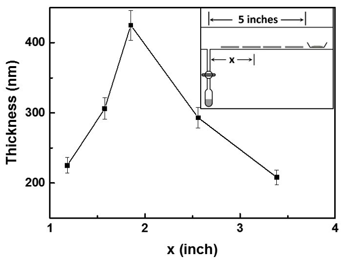
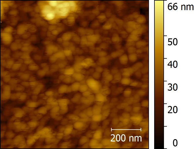
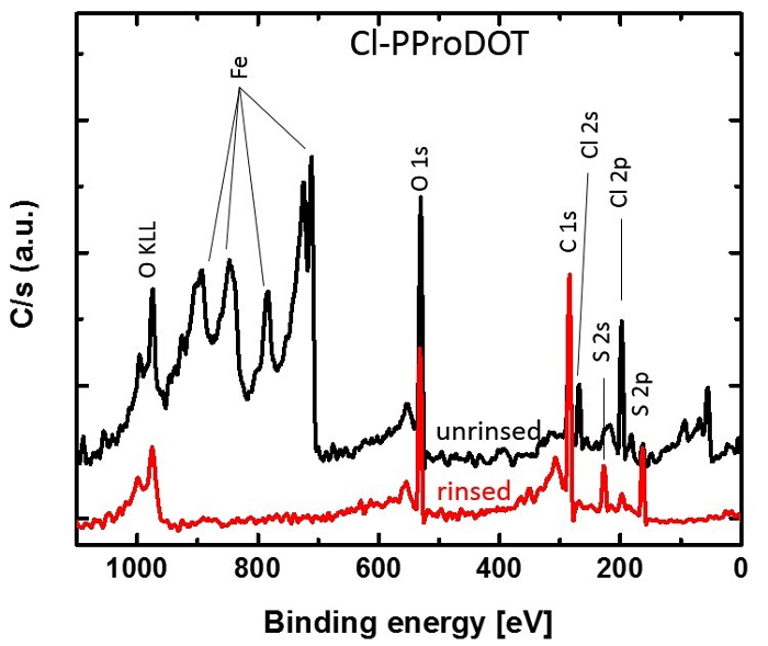
The thickness of Cl-PProDOT films formed on 1.3 cm x 2.5 cm glass slides placed at discrete lateral positions along the central tube were measured by a profilometer (Figure 3). Conductivities were calculated from resistivity measurements using a home-built four-point probe test station. The measured conductivity of a 100-nm thick Cl-PProDOT film on glass slides is 106 S/cm, which is sufficient to qualify this film as a potential electrode material. Figure 4 is the AFM image of 100-nm PProDOT film on a glass slide. X-ray photoelectron spectroscopy (XPS) spectra of Cl-PProDOT films on glass slides before and after rinsing were collected to prove that all residual FeCl3 was removed and prove that the conductivity arises solely from the polymer (Figure 5).
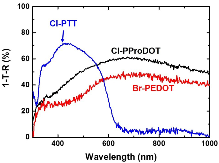
The UV/Vis absorption spectra of Cl-PProDOT, Cl-PTT and Br-PEDOT are shown in Figure 6. Polymers isolated immediately after deposition are p-doped because of the presence of excess oxidant. Accordingly, these films are colored blue due to polaronic and bipolaronic absorption bands in the red/NIR region. The broad, featureless absorption bands beyond 600 nm, the characteristic of bipolaron and polaron polarons, remain unchanged in the Cl-PProDOT and Br-PEDOT films before and after rinsing, which indicates that Cl-PProDOT and Br-PEDOT remain p-doped after rinsing. In contrast, Cl-PTT shows no polaron or bipolaron peaks after rinsing, indicating that Cl-PTT is fully de-doped during the rinsing process.
Optical micrographs and scanning electron microscopy (SEM) images of paper, corduroy fabric and a cotton towel before and after coating with Cl-PTT are shown in Figure 7. After coating, the pristine white substrates become dark red, indicating the presence of Cl-PTT coatings. All the three substrates are highly textured and disordered and have high surface area. The SEM images show that the films are uniform and conformal on the surface at a micrometer scale on all the three substrates.
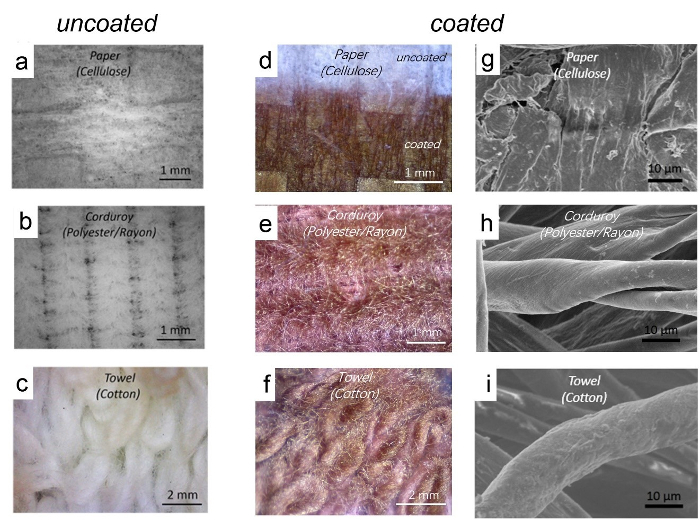
Figure 1. Deposition chamber setup. Schematic of the vapor deposition chamber for solid oxidants. Please click here to view a larger version of this figure.
Figure 2. Deposition chamber setup. Schematic of the tubular vapor deposition chamber for liquid oxidants. Please click here to view a larger version of this figure.
Figure 3. Thickness characterization of polymer films. Lateral polymer film thickness profile for the vapor polymerization of Cl-PProDOT.
Figure 4. Morphology characterization with AFM. AFM image of 100-nm Cl-PProDOT on a glass slide.
Figure 5. Elemental analysis. XPS spectra of a 1.3 cm x 2.5 cm glass slide coated with a 100-nm thick film of Cl-PProDOT immediately after deposition (black line) and after rinsing (red line) with methanol. The spectra reveal that iron salts are removed after rinsing.
Figure 6. Optical property characterization. Absorption spectra of Cl-PProDOT, Cl-PTT, and Br-PEDOT films on glass slides. Please click here to view a larger version of this figure.
Figure 7. Morphology characterization with optical microscope and scanning electron microscopy (SEM). Optical micrographs of pristine (a-c) and PTT coated (d-f) paper, polyester/rayon corduroy and cotton towel. SEM images (g-i) of PTT coated paper, polyester/rayon corduroy and cotton towel. Please click here to view a larger version of this figure.
Discussion
The mechanism of the reaction is oxidative polymerization. Polymer coating methods using the same mechanism include electropolymerization17 and vapor phase polymerization18. Electropolymerization requires a conductive substrate, lacks the advantage of uniform and conformal coating, and is an environmentally-unfriendly solution-based method19. The existing vapor phase polymerization method is similar to the method reported here but can only polymerize highly-volatile monomers20. Our method improved the chamber design of the existing method and can not only polymerize highly-volatile monomers but also non-volatile monomers. A number of new conducting and semiconducting polymers, such as PProDOT and PTT, were synthesized by vapor phase deposition for the first time using the method reported here20.
A critical step in the protocol is the timing of introducing the monomer vapor (step 1.2.8.). In the protocol, monomer vapor should be introduced to the chamber after FeCl3 vapor is formed, which can be told by the formation of red solid in the cool region. If the monomer vapor is introduced before there is FeCl3 vapor, the monomer vapor will reach the oxidant crucible and react with the solid oxidant directly. This will form a polymer layer covering the solid oxidant and prevent it from vaporization. On the other hand, if the monomer vapor is introduced too late, a thick layer of oxidant will be formed and it will affect the morphology of the polymer films.
The thickness of the polymer films can be controlled by the reaction time. The deposition rate of the polymer films presented here is ~10 nm/min and it can be controlled by the flow rate of the monomer. In this protocol, the flow rate of the monomer is controlled by adjusting the monomer temperature and the needle valve. If a more precise control is needed, a high temperature mass flow meter can be added between the monomer ampule and the monomer inlet.
We only present three examples of polymers in this protocol. For the coating of other polymers, the reaction conditions need to be optimized. The temperature of the oxidant can be kept the same as the protocol if the same oxidant is used. It has been reported that the process pressure affects the chain lengths of the polymers. Low process pressures result in a short conjugation21. The temperature of the oxidant should be optimized for each new monomer as well. A typical value to start with is the oxidant's melting point. Optimal substrate temperature usually increases as monomer temperature increases. For polymer films thinner than 500 nm, rinsing with copious methanol is enough for complete removal of all the residual oxidant and monomer. For thicker films, to completely remove residual FeCl3, the films can be immersed in a 1 M HCl water solution overnight and then rinsed with methanol.
A drawback of the reported deposition chamber is that it lacks an in situ QCM (quartz crystal microbalance) sensor and therefore, the deposition rates and film thickness cannot be monitored during the deposition. Film thickness is not uniform in the entire substrate region because of the lateral direction of mass transport. The lateral polymer film thickness profile for the vapor polymerization of Cl-PProDOT is shown in Figure 3. The polymer film formed in the middle between the monomer source and the oxidant source is the thickest, and the thickness progressively decreases from the middle to the two lateral directions. This confirms the lateral direction of mass transport from the two vapor sources to the middle of the substrate region and reveals that thickness can be controlled not only by reaction time but also by substrate position.
Since this method can deposit conducting and semiconducting polymers on arbitrary substrates, it can be applied in next-generation electronics on unconventional substrates such as wearable devices22,23. For example, conductive PEDOT or PProDOT can be coated on textiles on a large scale to make conductive textiles and they can be used in wearable electronics24. Also, vapor-deposited conjugated polymers can also be used as electrodes or active layers in electronics on paper to achieve light weight and low cost while solution-based coating methods are not applicable for paper substrates25.
In conclusion, we demonstrate a reactive vapor deposition method with which to create conductive PProDOT and PEDOT, and semiconducting PTT films on glass slides, paper, and textiles. Neither of these polymers have been synthesized by reactive vapor deposition before. This vapor deposition method can coat polymer films uniformly and conformally on highly disordered and textured, high surface areas substrates. This feature allows for future application of vapor deposited polymers in electronics devices on flexible and highly textured substrates.
Disclosures
The authors have nothing to disclose.
Acknowledgments
The authors gratefully acknowledge financial support from the US Air Force Office of Scientific Research, under agreement number FA9550-14-1-0128. T. L. A. also gratefully acknowledges partial support by the David and Lucille Packard Foundation.
References
- Kaltenbrunner M, et al. Ultrathin and lightweight organic solar cells with high flexibility. Nat. Commun. 2012;3:770. doi: 10.1038/ncomms1772. [DOI] [PMC free article] [PubMed] [Google Scholar]
- Savagatrup S, Printz AD, O'Connor TF, Zaretski AV, Lipomi DJ. Molecularly Stretchable Electronics. Chem. Mater. 2014;26:3028–3041. [Google Scholar]
- Lee J-Y, Connor ST, Cui Y, Peumans P. Semitransparent Organic Photovoltaic Cells with Laminated Top Electrode. Nano Lett. 2010;10:1276–1279. doi: 10.1021/nl903892x. [DOI] [PubMed] [Google Scholar]
- Kaltenbrunner M, et al. An ultra-lightweight design for imperceptible plastic electronics. Nature. 2013;499:458–463. doi: 10.1038/nature12314. [DOI] [PubMed] [Google Scholar]
- Jost K, et al. Carbon coated textiles for flexible energy storage. Energy Environ. Sci. 2011;4:5060–5067. [Google Scholar]
- Hu L, et al. Stretchable, Porous, and Conductive Energy Textiles. Nano Lett. 2010;10:708–714. doi: 10.1021/nl903949m. [DOI] [PubMed] [Google Scholar]
- Jost K, Dion G, Gogotsi Y. Textile energy storage in perspective. J. Mater. Chem. A. 2014;2:10776–10787. [Google Scholar]
- Ding Y, Invernale MA, Sotzing GA. Conductivity Trends of PEDOT-PSS Impregnated Fabric and the Effect of Conductivity on Electrochromic Textile. ACS Appl. Mater. Interfaces. 2010;2:1588–1593. doi: 10.1021/am100036n. [DOI] [PubMed] [Google Scholar]
- Hong KH, Oh KW, Kang TJ. Preparation and properties of electrically conducting textiles by in situ polymerization of poly(3,4-ethylenedioxythiophene) J. Appl. Polym. Sci. 2005;97:1326–1332. [Google Scholar]
- Xu J, et al. Fabric electrodes coated with polypyrrole nanorods for flexible supercapacitor application prepared via a reactive self-degraded template. Org. Electron. 2015;26:292–299. [Google Scholar]
- Du Y, et al. Thermoelectric Fabrics: Toward Power Generating Clothing. Sci. Rep. 2015;5:6411. doi: 10.1038/srep06411. [DOI] [PMC free article] [PubMed] [Google Scholar]
- Yatvin J, Sherman SA, Filocamo SF, Locklin J. Direct functionalization of Kevlar[registered sign] with copolymers containing sulfonyl nitrenes. Polym. Chem. 2015;6:3090–3097. [Google Scholar]
- Musumeci C, Hutchison JA, Samori P. Controlling the morphology of conductive PEDOT by in situ electropolymerization: from thin films to nanowires with variable electrical properties. Nanoscale. 2013;5:7756–7761. doi: 10.1039/c3nr03093h. [DOI] [PubMed] [Google Scholar]
- Allison L, Hoxie S, Andrew TL. Towards seamlessly-integrated textile electronics: methods to coat fabrics and fibers with conducting polymers for electronic applications. Chem. Commun. 2017;53:7182–7193. doi: 10.1039/c7cc02592k. [DOI] [PubMed] [Google Scholar]
- Alf ME, et al. Chemical Vapor Deposition of Conformal, Functional, and Responsive Polymer Films. Adv. Mater. 2010;22:1993–2027. doi: 10.1002/adma.200902765. [DOI] [PubMed] [Google Scholar]
- Goktas H, Wang X, Boscher ND, Torosian S, Gleason KK. Functionalizable and electrically conductive thin films formed by oxidative chemical vapor deposition (oCVD) from mixtures of 3-thiopheneethanol (3TE) and ethylene dioxythiophene (EDOT) J. Mater. Chem. C. 2016;4:3403–3414. [Google Scholar]
- Sadki S, Schottland P, Brodie N, Sabouraud G. The mechanisms of pyrrole electropolymerization. Chem. Soc. Rev. 2000;29:283–293. [Google Scholar]
- Bhattacharyya D, Howden RM, Borrelli DC, Gleason KK. Vapor phase oxidative synthesis of conjugated polymers and applications. J. Polym. Sci., Part B: Polym. Phys. 2012;50:1329–1351. [Google Scholar]
- Yamato H, et al. Synthesis of free-standing poly(3,4-ethylenedioxythiophene) conducting polymer films on a pilot scale. Synth. Met. 1996;83:125–130. [Google Scholar]
- Cheng N, Zhang L, Joon Kim J, Andrew TL. Vapor phase organic chemistry to deposit conjugated polymer films on arbitrary substrates. J. Mater. Chem. C. 2017;5:5787–5796. [Google Scholar]
- Borrelli DC, Lee S, Gleason KK. Optoelectronic properties of polythiophene thin films and organic TFTs fabricated by oxidative chemical vapor deposition. J. Mater. Chem. C. 2014;2:7223–7231. [Google Scholar]
- Jo WJ, et al. Oxidative Chemical Vapor Deposition of Neutral Hole Transporting Polymer for Enhanced Solar Cell Efficiency and Lifetime. Adv. Mater. 2016;28:6399–6404. doi: 10.1002/adma.201601221. [DOI] [PubMed] [Google Scholar]
- Wang M, et al. CVD Polymers for Devices and Device Fabrication. Adv. Mater. 2017;29:1604606. doi: 10.1002/adma.201604606. [DOI] [PMC free article] [PubMed] [Google Scholar]
- Kovacik P, Hierro Gd, Livernois W, Gleason KK. Scale-up of oCVD: large-area conductive polymer thin films for next-generation electronics. Mater. Horiz. 2015;2:221–227. [Google Scholar]
- Barr MC, et al. Direct Monolithic Integration of Organic Photovoltaic Circuits on Unmodified Paper. Adv. Mater. 2011;23:3500–3505. doi: 10.1002/adma.201101263. [DOI] [PubMed] [Google Scholar]


