

Abstract
In this paper, we present experimental results, of a small-model study, from which we plan to develop and apply a full-scale field-shaking system to reduce the screening current-induced field (SCF) in the 800-MHz HTS Insert (H800) of the MIT 1.3-GHz LTS/HTS NMR magnet (1.3G) currently under construction—the H800 is composed of 3 nested coils, each a stack of no-insulation (NI) REBCO double-pancakes. In 1.3G, H800 is the chief source of a large error field generated by its own SCF. To study the effectiveness of the field-shaking technique, we used two NI REBCO double-pancakes, one from Coil 2 (HCoil2) and one from Coil 3 (HCoil3) of the 3 H800 coils, and placed them in the bore of a 5-T/300-mm room-temperature bore low-temperature superconducting (LTS) background magnet. The background magnet is used not only to induce the SCF in the double-pancakes but also to reduce it by the field-shaking technique. For each run, we induced the SCF in the double-pancakes at an axial location where the external radial field Br > 0, then for the field-shaking, moved them to another location where the external axial field Bz ≫ BR. Due to the geometry of H800 and L500, top double-pancakes of 3 H800 coils will experience the considerable radial magnetic field perpendicular to the REBCO tape surface. To examine the effect of the field-shaking on the SCF, we tested each NI REBCO DP in the absence or presence of a radial field. In this paper, we report 77-K experimental results and analysis of the effect and a few significant remarks of the field-shaking.
Index Terms: Field-shaking, High field magnet, HTS insert, REBCO, SCF, Screening current
I. Introduction
For the development of >1 GHz NMR spectrometer system, with LTS outsert coil, an HTS insert coil must be used owing to its large in-field current-carrying capacities [1]. For a high-resolution NMR spectrometer system, its magnetic field must be uniform with an error field of ~0.01 ppm over a sample volume, making field shimming a must in the NMR magnet. The screening current-induced field (SCF), a diamagnetic field generated by each turn of HTS coil, is the major field error to incorporate an HTS insert for a high field LTS/HTS magnet. The magnitude of the diamagnetic field, the SCF is directly proportional to the superconductor size and critical current density [2]. Various studies have reported the screening current-induced field (SCF) generated by HTS coils [3–5].
Although the SCF in LTS magnets is much less severe than the one in HTS magnets, the so-called field-shaking technique to minimize the SCF error fields was proposed in 1986 for LTS magnets [6–8]. This technique has since been demonstrated, theoretically and experimentally to apply to HTS magnet [9–15]. Since the SCF by an HTS insert magnet can be >100 times greater than those typical by an LTS outsert magnet, it is critical to reduce or even eliminate the SCF-generated error field.
Francis Bitter Magnet Laboratory (FBML) of Massachusetts Institute of Technology (MIT) has developed a high-resolution 1.3-GHz/54-mm LTS/HTS NMR magnet (1.3G). The 1.3G consists of the 800-MHz HTS insert (H800) composed of 3 nested coils, each a stack of no-insulation (NI) REBCO double-pancakes (DPs), and the 500-MHz LTS outsert (L500). In 1.3G, H800 is the primary source of a large error field generated by its own SCF. Though L500 has adequately long length, the end-plane DPs of three H800 coils will experience the considerable radial magnetic field perpendicular to the REBCO tape surface. To examine the effect of the field-shaking on the SCF, we tested each NI REBCO DP in the absence or presence of a radial field. Based on our earlier field-shaking works [9–11], the experiment presented in this paper will help us to design a field-shaking system most suitable for our 1.3G. Unlike our previous field-shaking experiments in which we used either a stack of 3 REBCO 94mm OD NI DPs [10, 16] or a pile of 12-mm×12-mm square NI REBCO strips [11], we use 2 NI REBCO DPs, one from each of two H800 coils (HCoil2 and HCoil3) for our new experiment.
By a 5-T/300-mm room-temperature bore LTS background magnet, we induced the screening current at DP coils. The 5-T background magnet also reduces the SCF generated by the screening current by the trapezoidal field-shaking patterns, confirmed as effective for reduction of the SCF [16]. Considering the geometry of the LTS/HTS combination and the magnetic field within the HTS tape, the largest SCF error field occurs in the top and bottom end regions of a magnet, where the radial fields, applied- and self-field, are greatest. Therefore, we induced the SCF in the presence of the maximum external radial field and then, attempt to reduce it by the field-shaking technique in absence or presence of the external radial field.
II. Test Coils and Experimental Procedure
In this study, for the SCF induction and field-shaking tests, we used 2 NI REBCO DP coils, one from each of 2 H800 coils (Coils 2 and 3). Separate tests were used to characterize the field-shaking behavior of the HCoil2 DP and the HCoil3 DP, respectively. Specifications of 2 REBCO DPs are shown in Table I.
Table I.
Specifications of Tested HTS Double Pancake Coils
| Parameters | HCoil2 DP | HCoil3 DP |
|---|---|---|
| Conductor (REBCO) | ||
| Width; thickness [mm; μm] | 6.02; 76 | 6.04; 75 |
| Cu stabilizer thickness [mm] | 0.02 | 0.02 |
| Ic @ 77 K [A] | 188 | 190 |
| NI Double pancake Coil | ||
| ID [mm] | 151.04 | 196.90 |
| OD [mm] | 169.18 | 211.50 |
| Height [mm] | 12.198 | 12.200 |
| Turn per pancake | 120 | 96 |
| Self-inductance [mH] | 18.06 | 16.60 |
| Characteristic resistance, Rc [μΩ] | 322.1 | 491.9 |
| Time constant, τ [s] | 56.07 | 33.75 |
| Ic @ 77 K, self-field [A] | 42.81 | 67.41 |
The magnetic field near the ends of the H800 contains significant radial field component. To examine the effect of the field-shaking on the SCF, we tested each NI REBCO DP in the absence or presence of a radial field. This can be achieved by testing each NI REBCO DP at a selected position above or below the mid-plane of the 5-T LTS background magnet. From the geometry of the coil winding of the LTS background magnet, both Coil 2 and Coil 3 NI REBCO DPs will experience the maximum radial field at z = ±175 mm by the shape of the background magnet. Fig. 1 shows the position of the LTS background magnet and the tested DPs. The SCF was induced at z = −175 mm, and the field-shaking was done at the midplane. Dashed arrow lines mean that the DP attached to the flange plate is movable.
Fig. 1.

Position of HCoil2 DP (blue), and HCoil3 (red) in the 5-T/300-mm LTS background magnet (black).
The procedures to induce the SCF and later to reduce the SCF by the field-shaking are as below:
Place a single NI REBCO DP, at room temperature, at an axial location, z = −175 mm, below the mid-plane of the LTS background magnet.
Apply the magnetic field of 5 T to the single NI REBCO DP. The coil experiences the external radial field of 0.73-0.82 T, perpendicular to the tape surface, at this location.
Turn the NI REBCO DP into the superconducting state by cooling in a bath of liquid nitrogen, ready for inducing an SCF by flux trapping
Reduce the external magnetic field to zero, the process of which induces the SCF in the DP.
Relocate the DP to the mid-plane of the LTS background magnet for the field-shaking in the absence of the radial field; or stay at z = −175 mm, for the field-shaking in the presence of the radial field.
Apply a shaking field with the LTS background magnet using 0.6-1.6 T trapezoidal field injection, confirmed as effective for reduction of the SCF [16].
Map the radial field along the z-axis at the DP’s inner-most turn.
III. Induction of SCF and Field-Shaking Test
A. Field-shaking of HCoil2 DP: with and without radially shaking field
Following the above-noted procedure, we induced the SCF of HCoil2 DP at z = −175 mm and later positioned the DP to certain locations, z = 0 mm or −175 mm to reduce its SCF by field-shaking with or without the radial field. At z = 0 mm, the DPs experienced the axial component of the shaking field, Bsk-Z and almost zero radial component of the shaking field, Bsk-R. However, at z = −175 mm, both certain Bsk-Z and Bsk-R were applied to the DPs. The measurements of magnetic flux density distribution along the z-axis were repeated after every fieldshaking experiment.
Fig. 2 and 3 show BR, the measured radial field at the innermost turn of HCoil2 DP before and after field-shaking when the DP was located at z = 0 mm and −175 mm, respectively. To quantify and compare the effect of Bsk-R on the field-shaking for the reduction of the SCF, we calculated the line integrals of the measured magnetic flux density along the z-axis, ∫|Bscf|dz which has the unit of Wb/m and compare their normalization values. Fig. 4 shows the normalization value of that line integral for HCoil2 DP’s field-shaking tests.
Fig. 2.

Measured radial magnetic flux density, BR, at innermost turn region of HCoil2 DP along the z-axis axis when the DP was located at z = 0 mm.
Fig. 3.

Measured radial magnetic flux density, BR, at innermost turn region of HCoil2 DP along the z-axis when the DP was located at z = −175 mm.
Fig. 4.

Comparison of the field-shaking effect on HCoil2 DP with and without Bsk-R
When the field-shaking was performed at z = 0 mm with the absence of Bsk-R, six field-shaking applications of Bsk-Z of 0.6 T lowered the SCF to 20.9-23.2% of its originally induced SCF. After a precipitous drop to 22.8% at its first field-shaking application, the SCF was saturated at ~22% with more applications.
However, when the field-shaking was performed at z = −175 mm with Bsk-R of 0.14 T, three field-shaking applications of Bsk-Z of 0.6 T showed the saturation of the SCF reduction, at 89.1-91.1%. Because the SCF reduction showed the tendency of saturation, the additional tests were performed at z = 0 mm. Without Bsk-R, the first application of field-shaking reduced the SCF to 15.0% and two more applications reduced the SCF to 13.9% and 15.0%, respectively.
B. Field-shaking of HCoil3 DP
Similar to HCoil2 DP’s tests, we induced the SCF of HCoil3 DP at z = −175 mm and later moved the DP to z = 0 mm. In this test, when the SCF reduction showed the tendency of the saturation, Bsk-Z was increased.
Fig. 5 shows the BR of HCoil3 DP before and after field-shakings. Fig. 6 shows the comparison the field-shaking effect on HCoil3 DP with various Bsk-Z. It shows that five field-shaking applications of Bsk-Z = 0.6 T lowered the SCF to 54-51% of its originally induced SCF. Moreover, each four more field-shaking applications of Bsk-Z = 0.8 T and 1.2 T reduced the SCF to 48-42% and 32-28%, respectively. Moreover, three more field-shaking applications of Bsk-Z = 1.6 T reduced the SCF to 24-21%.
Fig. 5.

Measured radial magnetic flux density, BR, at innermost turn region of HCoil3 DP along the z-axis when the DP was located at z = 0 mm.
Fig. 6.

Comparison of the field-shaking effect on HCoil3 DP with various Bsk-Z.
C. Test summary and Discussion
Two tests on HCoil2 DP and a test on HCoil3 DP successfully reduced the SCF to approximately 20% of their initially induced values. Once the reduction of the SCF shows the tendency of saturation, unless the shaking-field was increased, the repetition of the field-shaking did not reduce the SCF anymore. The field-shaking of 0.6 T with the radial field of 0.14 T makes the field-shaking significantly less effective which shows only 11% reduction (100→89%), compared with the field-shaking of purely axial 0.6 T which shows 80% reduction (100→20%). Therefore, we may conclude that for 1.3G operation, the field-shaking for the reduction of SCF in H800 should be performed with the almost pure axial field.
In addition to the SCF reduction, though any current was not supplied to each DP, we observed the superconducting-to-normal transition in an HCoil3 DP test from the electromotive force between the background magnet and the NI DP coil. Fig. 7 shows this phenomenon during the test. Due to the existence of the turn-to-turn contact, NI coil can be expressed as a closed-loop RL circuit which can be charged by the external varying magnetic field in this test. The electromotive force from the background magnet is directly proportional to the current sweep rate of the background magnet. Therefore, for NI HTS magnets, the electromotive force is also directly proportional to the frequency of the field-shaking.
Fig. 7.
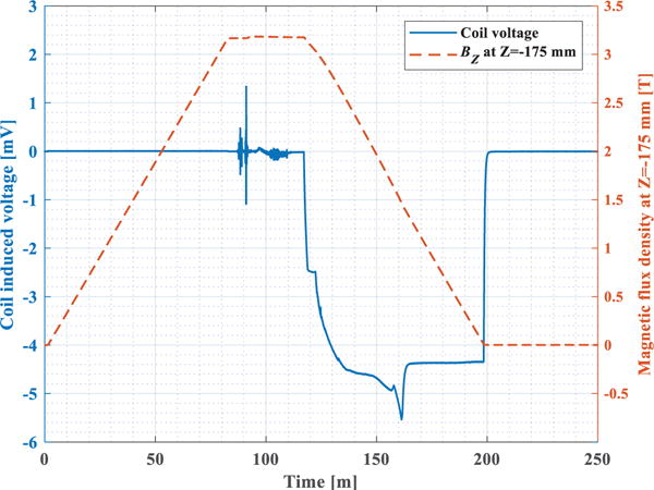
Coil induced voltage and the axial component of the magnetic flux density at z = −175 mm during the SCF induction of HCoil3 DP
IV. Conclusion
The measurement of the SCF and the effect on the field-shaking for its reduction was studied experimentally. Two NI REBCO DPs, one from each of two H800 coils (Coils 2–3) were tested. The field-shaking tests were performed at various amplitudes of shaking-field and DPs axial location. The experiment presented in this paper will help us to design a field-shaking system most suitable for our 1.3G. Based on the experimental results and analyses to date, we may conclude that:
The field-shaking technique successfully reduces the initial amount of the SCF even after one field-shaking application.
The higher shaking field is more effective on the reduction of the SCF than the lower.
Presence of the radial field during field-shaking made field-shaking significantly less effective than in the absence of one.
For the field-shaking of the HTS magnets adapting NI winding technique, the frequency of the field-shaking can be restricted within a certain limit due to the induced current by the electromotive force.
Table II.
Specifications of the 5-T/300-mm Room-Temperature Bore LTS Background Magnet
| Parameters | Values |
|---|---|
| Cooling method | Conduction cooling by 4 K GM refrigerator |
| Overall i.d.; o.d.; height [mm] | 327; 415; 338 |
| RT bore size; length [mm] | 300; 780 |
| Magnet constant [mT/A] | 61.52 |
| Center field at Iop of 81.268 A [T] | 5.0 |
| Self-inductance [H] | 143 |
Acknowledgments
Research reported in this publication was supported by the National Institute of General Medical Sciences of the National Institutes of Health under award number R01GM114834.
Footnotes
Color versions of one or more of the figures in this paper are available online at http://ieeexplore.ieee.org.
Contributor Information
Jiho Lee, Francis Bitter Magnet Laboratory of Plasma Science and Fusion Center, Massachusetts Institute of Technology, Cambridge, MA 02139 USA.
Dongkeun Park, Francis Bitter Magnet Laboratory of Plasma Science and Fusion Center, Massachusetts Institute of Technology, Cambridge, MA 02139 USA.
Philip C. Michael, Francis Bitter Magnet Laboratory of Plasma Science and Fusion Center, Massachusetts Institute of Technology, Cambridge, MA 02139 USA
So Noguchi, Francis Bitter Magnet Laboratory of Plasma Science and Fusion Center, Massachusetts Institute of Technology, Cambridge, MA 02139 USA.
Juan Bascuñán, Francis Bitter Magnet Laboratory of Plasma Science and Fusion Center, Massachusetts Institute of Technology, Cambridge, MA 02139 USA.
Yukikazu Iwasa, Francis Bitter Magnet Laboratory of Plasma Science and Fusion Center, Massachusetts Institute of Technology, Cambridge, MA 02139 USA.
References
- 1.Iwasa Yukikazu, Hahn Juan Bascuñán Seungyong, Voccio John, Kim Youngjae, Lécrevisse Thibault, Song Jungbin, Kajikawa Kazuhiro. A High-Resolution 1.3-GHz/54-mm LTS/HTS NMR Magnet. IEEE Trans Appl Supercond. 2015 Jun;25(3) doi: 10.1109/tasc.2014.2363496. Art. no. 4300205. [DOI] [PMC free article] [PubMed] [Google Scholar]
- 2.Yanagisawa Y, Nakagome H, Koyama Y, Hu R, Takao T, Hamada M, Kiyoshi T, Takahashi M, Maeda H. Effect of current sweep reversal on the magnetic field stability for a Bi-2223 superconducting solenoid. Phys C Supercond its Appl. 2009 Aug;469(22):1996–1999. [Google Scholar]
- 3.Hahn Seung-yong, Bascunan Juan, Kim Woo-Seok, Bobrov Emanuel S, Lee Haigun, Iwasa Yukikazu. Field mapping, NMR lineshape, and screening currents induced field analyses for homogeneity improvement in LTS/HTS NMR magnets. IEEE Trans Appl Supercond. 2008;18(2):856–859. doi: 10.1109/TASC.2008.921225. [DOI] [PMC free article] [PubMed] [Google Scholar]
- 4.Gu Chen, Qu Timing, Han Zhenghe. Measurement and calculation of residual magnetic field in a Bi2223/Ag magnet. IEEE Trans Appl Supercond. 2007 Jun;17(2):2394–2397. [Google Scholar]
- 5.Koyama Y, Takao T, Yanagisawa Y, Nakagome H, Hamada M, Kiyoshi T, Takahashi M, Maeda H. Towards beyond 1 GHz NMR: Mechanism of the long-term drift of screening current-induced magnetic field in a Bi-2223 coil. Phys C Supercond its Appl. 2009 Mar;469(13):694–701. [Google Scholar]
- 6.Funaki Kazuo, Yamafuji Kaoru. Abnormal transverse-field effects in nonideal type ii superconductors i. A linear array of monofilamentary wires. Jpn J Appl Phys. 1982 Feb;21(2):299–304. [Google Scholar]
- 7.Funaki Kazuo, Nidome Teruhide, Yamafuji Kaoru. Abnormal transverse-field effects in nonideal type II superconductor II. influence of dimension ratios in a superconducting ribbon. Jpn J Appl Phys. 1982 Aug;21(8):1121–1126. [Google Scholar]
- 8.Funaki Kazuo, Noda Minoru, Yamafuji Kaoru. Abnormal transverse-field effects in nonideal type II superconductor III. a theory for an AC-induced decrease in the semi-quasistatic magnetization parallel to a DC bias field. Japanese J Appl Phys. 1982 Nov;21(11):1580–1587. [Google Scholar]
- 9.Kajikawa Kazuhiro, Gettliffe Gwendolyn V, Chu Yong, Miyagi Daisuke, Lécrevisse Thibault P, Hahn Seungyong, Bascuñán Juan, Iwasa Yukikazu. Designs and Tests of Shaking Coils to Reduce Screening Currents Induced in HTS Insert Coils for NMR Magnet. IEEE Trans Appl Supercond. 2015 Jun;25(3) doi: 10.1109/tasc.2014.2363495. Art. no. 4300305. [DOI] [PMC free article] [PubMed] [Google Scholar]
- 10.Miyagi Daisuke, Hahn Seungyong, Lécrevisse Thibault, Ahn Min Cheol, Song Jung-Bin, Bascunan Juan, Iwasa Yukikazu. An experimental study on ‘field-shaking’ technique to reduce screening-current fields in a noninsulated REBCO magnet of double-pancake coils. presented at the 2016 Appl Supercond Conf; Denver, CO, USA. Sep 4–9, 2016. [Google Scholar]
- 11.Liang Fei, Qu Timing, Zhang Zhenyu, Sheng Jie, Yuan Weijia, Zhang Yukikazu Iwasa Min. Vortex shaking study of REBCO tape with consideration of anisotropic characteristics. Supercond Sci Technol. 2017 Aug;30(9):94006. doi: 10.1088/1361-6668/aa7f69. [DOI] [PMC free article] [PubMed] [Google Scholar]
- 12.Brandt Ernst Helmut, Mikitik Grigorii P. Why an ac magnetic field shifts the irreversibility line in type-II superconductors. Phys Rev Lett. 2002 Jul;89(2) doi: 10.1103/PhysRevLett.89.027002. Art. No. 027002. [DOI] [PubMed] [Google Scholar]
- 13.Mikitik Gregorii P, Brandt Ernst Helmut. Theory of the longitudinal vortex-shaking effect in superconducting strips. Phys Rev B. 2003 Mar;67(10) Art. no. 104511. [Google Scholar]
- 14.Brandt Ernst Helmut, Mikitik Grigorii P. Shaking of the critical state by a small transverse ac field can cause rapid relaxation in superconductors. Supercond Sci Technol. 2004 Feb;17(2):S10–S14. [Google Scholar]
- 15.Kajikawa Kazuhiro, Okabe Yuma. Reduction of Screening-Current-Induced Fields in an HTS Tape Winding Using Toroidal Arrangement of Shaking Coil. IEEE Trans Appl Supercond. 2016 Jun;26(4) Art. no. 4400504. [Google Scholar]
- 16.Bascuñán Juan, Hahn Seungyong, Lécrevisse Thibault, Song Jungbin, Miyagi Daisuke, Iwasa Yukikazu. An 800-MHz all-REBCO Insert for the 1.3-GHz LTS/HTS NMR Magnet Program-A Progress Report. IEEE Trans Appl Supercond. 2016 Jun;26(4) doi: 10.1109/TASC.2015.2512045. Art. no. 4300205. [DOI] [PMC free article] [PubMed] [Google Scholar]