Abstract
The purpose of this investigation is to fabricate PDMS membranes with reliable surface roughness in order to reduce the surface resistances and to study its impact on the permeation rate. The permeance of CO2 through PDMS membranes with rough surfaces at nanoscale is studied and compared with the one of membranes with flat surfaces. At very low thickness, rough membranes have a permeance greater than that of membranes with flat surfaces. The enhancement occurs in a regime where the gas transport is sorption desorption surface rate limited, and cannot be explained by the increase in surface area due to the corrugation. The analysis, introducing a phenomenological model in analogy with electrical flow, indicates that nano-corrugation reduces the surface resistance. To test the model, the permeance of N2 is also measured in the same experimental conditions and the influence of surface roughness on permeation rate of CO2, He, CH4 and N2 is studied. The comparison among the gases suggests that the Henry’s coefficient depends on the surface roughness and allows discussing the role of roughness on membrane selectivity.
Introduction
Rubbery polymer membranes have recently received great attention thanks to their suitability in several areas of application, and, above all, in gas separation1–5. A recent paper6 has shown that for membranes of small thickness (typically below 250 µm) this class of polymers exhibits an apparent permeability which, for a given diffusivity D and solubility S, is lower than the value PHF = DS indicated by Fick’s and Henry’s laws. In particular
| 1 |
where L is the membrane thickness and LC is a characteristic length. Equation (1) accurately reproduces a large number of permeability experimental values of rubbery polymer membranes5 having a thickness such that the partitioning process of the gas at the interfaces never reach the equilibrium value7–9. The results indicate that for small L the measured permeability decreases with L, and the length scale LC determines the transition from Surface Limited Regime (SLR) to Diffusion Limited Regime (DLR). Permeability in SLR is lower than the DLR value PHF. The permeation rate of the membrane is limited by the sorption desorption rate at the surfaces and any further increase can then be achieved by changing the surface kinetics. The surface kinetics limits also the permeance PL in fact
| 2 |
is limited to the value of PHF/LC as the thickness L goes to zero.
The mechanism of the surface sorption desorption limited rate transport is easily described by
| 3 |
where A is the cross-sectional surface area available for permeation, Q is the permeation rate and Δp the partial pressure difference across the membrane. Equation (3) defines a membrane resistance R = L/(PA), equivalent to the electrical resistance. When the membrane is very thin, feed and permeate surfaces limit the partitioning process, which is not anymore ‘near’ equilibrium. In these conditions a series of feed RS, permeate RS surface membrane resistances and bulk resistance Rb describes the membrane resistance R. Δp results
| 4 |
As consequence of eqs (1), (3) and (4) , .
In terms of resistances, PL results
| 5 |
Since Rb → 0 as L → 0 from equation (5) appears that PL is limited by the resistances of the two surfaces Rs and consequently any further increase of permeation rate can be only achieved by their reduction.
At the contrary when L >> LC results Rb >> Rs and the permeance assume the standard value PL = PHF/L.
Since the resistances depend on surfaces, we study the effects on the gas permeation induced by roughening the feed and permeate membrane surfaces.
There are several examples in literature that suggest that surface roughness may increase the permeation rate of membranes. Hirose, Ito and Kamiyama10 for instance, studying the relationship between skin layer surface structures of cross-linked aromatic polyamide composite reverse osmosis membranes, observed that membranes, whose skin layer surface structures were rough on the scale of 1 μm, produced higher fluxes. They observed that there is a linear relationship between surface roughness and flux, concluding that the flux increase may be regarded as an enlargement of the effective membrane area. Yave et al.11,12, studying materials to design membrane for carbon dioxide separation, considered that nano-corrugated surface might contribute to increase the permeability. Gronda, Buechel and Cussler13 performing a theoretical model of corrugated membranes, predicted, for small thicknesses, an increase of the flux by a factor δ = Af/A where Af is the area of the flattened surface and A the cross-sectional surface area of membrane. Goodyer and Bunge14 made a more sophisticated mathematical model to explain the mass transfer through membranes with surface roughness. Peters, Lammertink and Wessling15 compared flat and micro-patterned membrane having the same volume, observing and predicting a permeability enhancement for the latter. Pisarev et al.16,17 simulating hydrogen permeation through rough membranes, observed that in SRL, surface roughness affects strongly the dynamics of permeation. They investigated membranes with rough surfaces in different conditions (rough on one side and on both sides) and compared the results with membranes with flat surfaces. In addition, they showed that permeation rate is practically independent on roughness in the Diffusion Limited Regime. Cole, Holter and Pfeifer18 studying the adsorption at low coverage on rough surfaces, showed that the Henry’s law coefficient depends on fractal dimensionality of the surface.
All these results indicate the need of further investigations to fully understand the role of surface roughness on the permeation rate. The purpose of this paper is to fabricate membranes with reliable surface roughness at nano scale in order to reduce the surfaces resistances and study its impact on the permeation rate and selectivity. Measurements of membrane permeance at different conditions (rough on one side and on both sides) are carried out and the results are compared with membranes with flat surfaces. The paper considers the case of CO2 and N2 flowing through PolyDiMethylSiloxane (PDMS) membranes of different thickness and moreover investigates the permeance of CO2, He, CH4 and N2 at different surface roughness. The comparison among the gases allows to discuss the role of roughness on membrane selectivity.
Method
Membrane fabrication
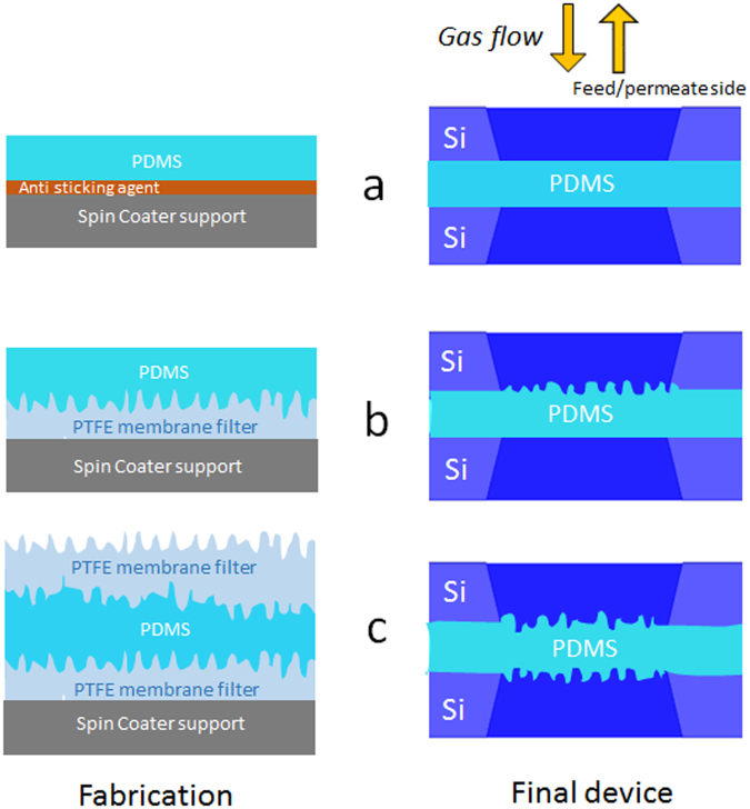
The procedure to fabricate the membranes is described in ref.6. In the present paper a mask is mounted on the membrane as described in Fig. 1 to guarantee the same exposed area to feed and permeate side. This modification avoids lateral diffusion as observed frequently in composite membranes19. Figure 1 shows the device fabrication. A 5 mm × 5 mm commercial square silicon chip with a hole in the center (purchased from Applied NanoStructures, Inc. USA) supports a PDMS film (see Fig. 1a). An identical square silicon chip (the mask) covers the PDMS film (see Fig. 1b). The complete device consisting in a PDMS membrane of thickness L having same permeate and feed area A is reported in Fig. 1c. The membrane is symmetric and can be used on both sides.
Figure 1.
PDMS membrane fabrication. (a) PDMS on silicon chip. (b) PDMS covered by a second silicon chip. (c) Cross section of the PDMS membrane of area A and thickness L. The membrane is symmetric and can be used from both sides.
Three kinds of PDMS membranes are fabricated: a) a membrane (hereafter reported as FF) with both flat surfaces, b) a membrane (FC) with only one corrugated surface and c) a membrane (CC) with both corrugated surfaces. FF is fabricated as shown in Fig. 2a. The fabrication of corrugated surfaces in FC and CC is reported in Fig. 2b,c. FC membrane is realized (Fig. 2b) by spin coating the non-cured PDMS on a hydrophobic polytetra-fluorethylene (PTFE) filter (0.2 μm pore size, purchased from Sartorium Stedim Biotech GmbH) and subsequently transferred on the silicon chip by the same technique shown in ref.6 and schematically reported in Fig. 1. CC membrane is fabricated by the following steps: a) the PDMS film is spin coated on a PTFE filter and non-cured, b) a PTFE filter is placed on the non-cured PDMS film, c) the PDMS film is cured as in ref.6, and d) the upper PTFE filter is mechanically removed resulting in a double-corrugated membrane (Fig. 2c). The corrugated surface is a replica of the PTFE filter surface. By changing the filter is possible to change in a reproducible manner the surface roughness. The present paper uses two different membranes with roughness of 86 nm and 220 nm (see Table 1).
Figure 2.
Fabrication and assembly of flat and corrugated membranes. (a) Flat FF. (b) One side corrugated FC. (c) Double side corrugated CC.
Table 1.
Thickness L and cross-sectional surface area A of PDMS membranes.
| Rq = 86 nm | Rq = 220 nm | ||||||||||||||||
|---|---|---|---|---|---|---|---|---|---|---|---|---|---|---|---|---|---|
| FC membranes | FF membranes | CC membranes | FC membranes | ||||||||||||||
| L (μm) | 3 | 7 | 15 | 32 | 43 | 500 | 5.3 | 10 | 32 | 70 | 590 | 10 | 15 | 20 | 30 | 1100 | 30 |
| A (μm2) × 10−2 | 19 | 24 | 42 | 220 | 257 | 23 | 400 | 350 | 235 | 7 | 21 | 18 | 19 | 58 | |||
| A (mm2) | 78.5 | 78.5 | 78.5 | ||||||||||||||
Membranes with thicknesses ranging from a few micrometers to about 70 μm are obtained by varying the rotational speed of the spin coater. In order to guarantee a measurable gas flow the dimensions of the cross-sectional surface area are different for different membrane thickness; to maintain a good mechanical stability, if necessary, thinner membranes have smaller area. The membranes with thicknesses in the mm range have been fabricated without spinning, using a Petri’s dishes as support and transferred directly on the copper disk of the gas permeation apparatus following the procedure described in ref.6. Table 1 reports the dimensions L and A for all the membrane tested.
Characterization
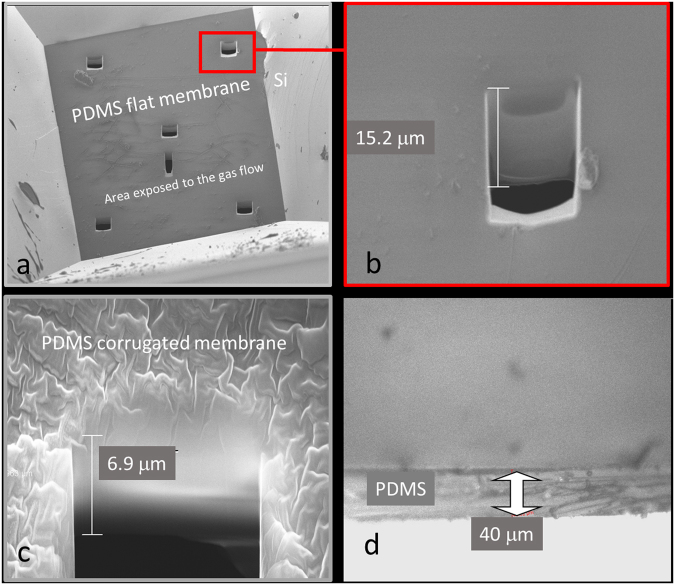
Scanning Electron Microscope (SEM) is used to measure membrane thickness for L < 20 μm through the fabrication of a cross section layer using a Focused Ion Beam (FIB)20. Optical microscope is used to measure L of thicker membranes (L > 20 μm). In Fig. 3, representative SEM and optical images of some membranes are shown. For any sample, L is the mean value of repeated measurements in different points and the maximum error is the measurement error.
Figure 3.
Thickness measurements. (a) SEM image of the PDMS membrane with six cross sections obtained by FIB. (b) SEM magnification of one of the cross section. (c) SEM magnification of a cross section of a thinner membrane with corrugated surface. (d) Optical microscope image of a thicker membrane.
Atomic Force Microscope (AFM) monitors the surface morphology of flat and corrugated surfaces. By using WSxM freeware scanning probe software and averaging on several samples, we determined the flattened area A* and the root mean square roughness of each membrane21. Figure 4 reports the AFM image of three membrane surfaces used in the present experiment. The root mean square roughness of the corrugated surfaces is Rq = 220 nm (Fig. 4a) and the ratio ε = A*/A between the flattened area and the surface area A is ε = 1.16 ± 0.05. The root mean square roughness of the corrugated surface of Fig. 4b is Rq = 86 nm and the ratio ε is 1.13 ± 0.05. The flat surface has Rq = 0.6 nm. All membranes used have been monitored with AFM, obtaining the same values of Rq within 10%. Table 1 reports L, A and Rq for all the membrane tested.
Figure 4.
AFM images. (a) AFM 3D view of three membranes with Rq = 220 nm. (b) AFM 3D view membrane with Rq = 86 nm. (c) AFM 3D view of a flat surface Rq = 0.6 nm.
To check the goodness of the preparation procedure, Electron Dispersive X-Ray (EDX) has been carried out on rough surfaces to eventually reveal fluorine contaminants coming from the PTFE filter. Within the 1 μm of spatial resolution of EDX, the PDMS rough surfaces are not contaminated.
Gas permeation apparatus
In order to measure the permeation rate Q through the membrane we have used an experimental apparatus, equipped with a Residual Gas Analyzer, based on selective on-line measurements of gas fluxes, reported in ref.6. Respect to the variable-volume or variable-pressure methods this set up allows to measure transient fluxes, directly, rapidly, and selectivity. To increase the accuracy of the measurements, respect to ref.6, the vacuum chamber has been equipped with a Spinning Rotor Gauge (SRG). PL is determined by measuring the partial pressure difference across the membrane Δp = pu − pd, where pu is the upstream pressure and pd the downstream pressure, and the gas flux J = Q/A as
| 6 |
The permeation rate Q, is the product of the pumping speed s of the system by pd. In this experiment, the SRG is used to calibrate the Quadrupole Mass Spectrometer (QMS), and PL is measured at pu = 1.013 × 10⁵ Pa. The error on Q depends on the uncertainty of s and pd, that, considering measurements of pd after SRG calibration of QMS, has a relative error less than 5%. Taking into account the error on membrane area A, the relative error on J results less than 10%. Since the error on Δp is less than 0.5%, the measured permeance has a relative error less than 10%. In the worst condition, the measurements of the membrane thickness L have an accuracy better than 20% as discussed in ref.6. The small roughness of the membranes does not affect the thickness value. The purity grade of the gases tested is N5.0.
Results and Discussion
By following the procedure illustrated in section Method, we fabricated 5 FF, 6 FC and 5 CC membranes with different thickness with surface roughness Rq = 86 nm (see Table 1). FC have been measured in two different conditions: a) with the corrugated surface on the feed side and b) with the corrugated surface on the permeate side. The two configurations give the same permeance within the experimental errors. Gas permeation measurements for all the membranes are performed for two gases CO2 and N2.
Figure 5 reports the values of CO2 advantage coefficient EXX defined in analogy to what reported in ref.15 as:
| 7 |
Figure 5.
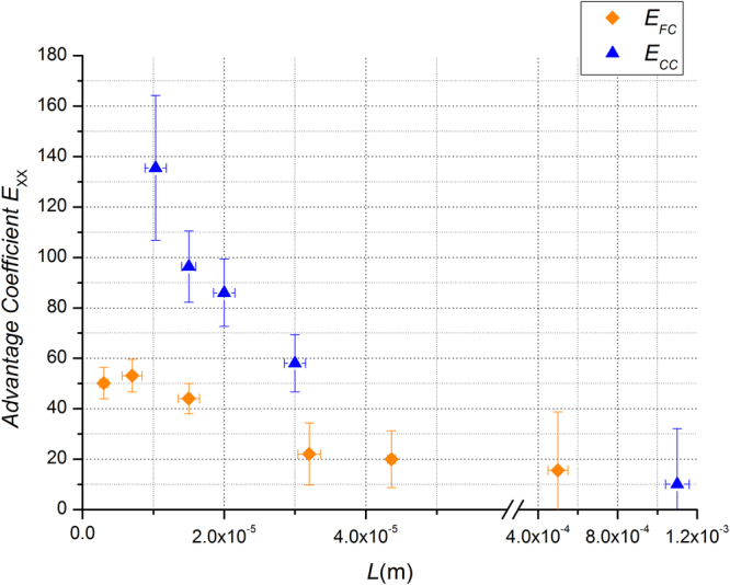
Advantage CO2 coefficient as function of thickness . ⬥ EFC, advantage coefficient for FC membranes ▲ ECC, advantage coefficient for CC membranes. The tracer gas is CO2, the upstream pressure is pu = 1.013 × 10⁵ Pa and the temperature = 293 K.
In eq. (7) JXX is the flux, XX indicates the specific membrane (FC or CC) and JFF is the flux for the membranes with the flat surfaces. As shown in Table 1 the thickness of the flat membranes FF in most cases does not correspond to the respective thickness of the FC and CC membranes. The value of JFF to calculate the advantage coefficient defined by equation (6) is obtained by interpolating the curve that fits the permeance of the FF membranes reported in Fig. 6. The flux is always measured with the same Δp among the samples with different thicknesses, in particular with pu = 1.013 × 10⁵ Pa and pd < 10−4 Pa. EXX quantifies the advantage obtained by using rough membranes respect to flat membranes.
Figure 6.
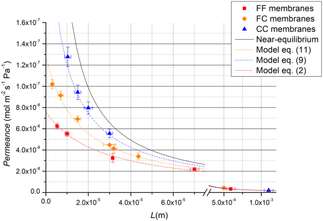
Permeance PL of CO2 as function of thickness L. ◼ FF membranes ⬥ FC membranes ▲ CC membranes. The dotted lines are the best fit curves following the models of eqs (2), (8) and (10) respectively for FF, CC and FC membranes. The best fit parameters are reported in Table 2 for CO2. The continuous curve represents the condition of near equilibrium PL = PHF/L. The tracer gas is CO2, the upstream pressure is pu = 1.013 × 10⁵ Pa and the temperature = 293 K.
The enhancement is significantly strong. FC membrane at L = 7 μm shows a permeance which is 53% larger than FF. The effect is even stronger when both surfaces are corrugated (CC membranes). At the smallest thickness (L = 10 μm) CC has an experimental advantage of 140% which corresponds to an increment in permeance of a factor 2.4 respect to the flat membrane and shows a permeance which is 61% of the value expected in near equilibrium conditions PL = PHF/L. The effect is significant only at the micro-scale while at higher values of L the advantage coefficient is close to zero. In fact for CC at L = 1 mm, ECC is 10% and for FC at L = 0,5 mm, EFC is 15% but, due to the incertitude of the measurements, we cannot tell them apart from FF. Finally, we point out that the value of the permeability for FF (L = 0.5 mm) membranes is in agreement with that reported in the literature for the system CO2/PDMS of comparable thickness (L = 100 μm)22. The flux enhancement at low thicknesses cannot be explained by the increase in surface area due to the corrugation. In fact the value of = 1.13 ± 0.05 measured by AFM is not able to justify the enhancement factor observed for CC and FC in the micro scale.
Figure 6 reports PL as function of thickness L for FF, FC and CC membranes with surface roughness Rq = 86 nm for CO2. There is a strong enhancement of PL at very low thickness, while, on the contrary, for macroscopic ones, PL has the same values for FF, FC and CC. Since the characteristic length of the system is LC = 30 µm, as recently determined6, the enhancement occurs in the SLR regime where the gas transport is surface sorption desorption rate limited. The rise is even more pronounced when both feed and permeate membrane surfaces are corrugated, CC has, in fact, a much larger permeance of both FF and FC.
The experiment shows that the surface resistivity ρs of permeate and feed surfaces decreases significantly respect to that of the flat surfaces. By defining the surface resistivity of the corrugated permeate and feed surfaces as ρsc = βρs, where β < 1 the equations (4) and (2), valid for FF membranes, for CC and FC respectively assume the following form:
| 8 |
| 9 |
| 10 |
| 11 |
The analysis of the data has been performed first by fitting the permeance as function of thickness for FF membranes of Fig. 6 with eq. (2) by taking PHF and LC as fitting parameters. The results are reported in Table 2. Subsequently, for CC membranes, PL is fitted with eq. (9) using β as fitting parameter and taking PHF and LC from Table 2. A similar procedure has been followed for FC membranes, PL is fitted by using eq. (11) with β as fitting parameter, PHF and LC are taken from Table 2. The analysis is carried out with Least Absolute Residuals (LAR) method considering that the data have less anomalies and the coefficient of determination R2 describes the goodness of the fits23. We point out that the permeability measurements of FC membranes give the same values independently from which is the corrugated interface (up or downstream). The obtained values of PHF and LC, listed in Table 2, are in agreement with those reported in refs6,21 and result more precise thanks to the improvement of the experimental set up (see section Method). The β values listed in Table 2 for CO2 gas are, within the experimental error, the same fitting the data with eq. (9) or with eq. (11) confirming the validity of the analysis.
Table 2.
Permeability PHF, characteristic lengths LC, and parameter β.
| CO 2 | |||||
|---|---|---|---|---|---|
| PHF × 1012 (mol m−1 s−1 Pa−1) | LC (µm) | β × 10−1 | β × 10−1 | R 2 | |
| FF | 2.0 ± 0.4 | 26 ± 8 | 0.997 | ||
| CC | 2.0 | 2.2 ± 0.1 | 0.999 | ||
| FC | 2.0 | 2.2 ± 0.1 | 0.993 | ||
| N 2 | |||||
| P HF × 10 13 (mol m −1 s −1 Pa −1 ) | L C (µm) | β × 10−2 | β × 10−2 | R 2 | |
| FF | 2.3 ± 0.4 | 14±4 | 0.998 | ||
| CC | 2.3 | 2.0 ± 0.4 | 0.999 | ||
| FC | 2.3 | 2.0±0.4 | 0.995 | ||
| He | |||||
| P HF × 10 13 (mol m −1 s −1 Pa −1 ) | L C (µm) | β × 10−3 | |||
| FF | 3 ± 1 | 13 ± 3 | |||
| FC | 5 ± 2 | ||||
| CH 4 | |||||
| P HF × 10 13 (mol m −1 s −1 Pa −1 ) | L C (µm) | β × 10−2 | |||
| FF | 5 ± 1 | 17 ± 4 | |||
| FC | 2.3±0.9 | ||||
In addition, we performed the same measurements by using N2 as tracer gas. Figure 7 reports PL as function of thickness L for FF, FC and CC membranes with surface roughness Rq = 86 nm.
Figure 7.
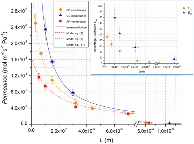
Permeance PL and advantage coefficient of N2 as function of thickness L. ■ FF membranes ◆ FC membranes ▲ CC membranes. The dotted lines are the best fit curves following the models of eqs (2), (8) and (10) respectively for FF, CC and FC membranes. The best fit parameters for N2 are those reported in Table 2. The continuous curve, that represents the condition of near equilibrium PL = PHF/L, is overlapped on best fit curve of eq. (8). The tracer gas is N2, the upstream pressure is pu = 1.013 × 10⁵ Pa and the temperature = 293 K. The inset shows the N2 advantage coefficient as function of thickness . ◆ EFC for FC membranes ▲ ECC, for CC membranes.
The trend of the permeance with thickness is very similar to that observed in the case of CO2. There is a strong enhancement of PL at low thickness, that also in this case cannot be explained by an increase of the surface area. At large thickness, PL assumes the same values for FF, FC and CC as occurs for CO2. The advantage coefficient in the inset shows that for this system the enhancement in permeance is even more pronounced. In this case, the model of equations (2), (9) and (11) describes quite well the observed behavior. The analysis of the data has been performed as previously described for CO2. Table 2 reports the values of the fitting parameters.
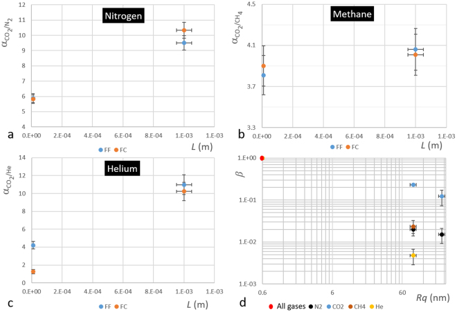
In addition, we measured the permeance of He and CH4 through two FF membranes with L = 2 mm and L = 10 µm and two FC membranes of the same thicknesses (data not shown). From these data, by using eq. (2) and performing the same analysis followed for N2 and CO2 we obtained the values of PHF, Lc and β reported in Table 2 for these gases. Figure 8(d) shows the parameter β for all four gases as function of roughness Rq. For CO2 and N2, an FC membrane with surface roughness Rq = 220, have been also tested and reported. It is clear from Fig. 8(d) that the change in resistivity depends on type of permeating gas.
Figure 8.
Selectivity as function of thickness L and surface resistance as function of corrugation Rq. (a) CO2 selectivity respect to N2, (b) CO2 selectivity respect to CH4 and (c) CO2 selectivity respect to He for FF and FC membranes. FC membrane have the feed surface with a Rq = 86 nm. (d) Surface resistance for N2 CO2, CH4 and He at different surface roughness Rq.
In order to complete the analysis, we calculated from the permeability data the selectivity αij = Pi/Pj, where Pi is the permeability of the faster gas and Pj that of the slower gas, for CO2 respect to He, CH4 and N2. The results for FF and FC membranes are reported in Fig. 8(a,b and c).
The results for FF membranes follow the model of the permeability previously described6 since LC of CO2 is grater then LC for He, CH4 and N2 (see Table 2). The selectivity of CO2 respect to those gases decrease with L as shown in Fig. 8(a–c).
The results for FC membranes show that at L = 10 µm and Rq = 86 nm the selectivity coefficient αCO2/He change significantly respect to those for FF membranes, while no change of αCO2/N2 and αCO2/CH4 occurs. Also in this case the effect is related to the modification of the surface resistance due to the roughness. These results suggest that, beside membrane permeance, the surface corrugation can modify also its selectivity. The change of both selectivity and permeance indicates that the effect is gas dependent.
Conclusions
We fabricated PDMS membranes with nano-corrugated surfaces to study the effect of the corrugation on the permeation rate and selectivity. We measured CO2 and N2 permeance as function of membrane thickness L ranging from L = 3 µm to L = 1 mm. In both cases, we identified two different diffusion regimes (SLR and DLR) where the nano-corrugation plays a different role. In DLR, the permeation rate is practically independent of the roughness while in SLR the permeation rate increases significantly with respect to membranes with flat surfaces. The enhancement is particularly strong for CC membranes. For FC the effect is smaller and independent of which side of the membrane is rough. The flux enhancement at low thicknesses cannot be explained by the increase in surface area due to the corrugation. In the case of CO2 for the CC membranes with smallest thickness measured, L = 10 μm, the permeance increases by a factor of 2.4 with respect to the flat membranes. In this case the membrane shows a permeance which is 61% of the value expected in near equilibrium conditions PL = PHF/L. When N2 is used instead of CO2, the effect is more pronounced.
The analysis of the data collected using both gases gives a satisfactory phenomenological explanation of the reduction of the surface resistance of the rough membrane with respect to the flat one. The same results are obtained in the case of He and CH4. The change of the surface resistance RS with roughness affects also the selectivity of CO2 respect to He, CH4 and N2. The experimental results indicate clearly that the surface roughness influences significantly both membrane permeance and selectivity, offering an appealing method to increase the performance of thin membranes.
Electronic supplementary material
Acknowledgements
This work was supported by grants from the Italian Ministry of Education, University and Research, Flagship Project Nanomax. We thank D. Repetto for supporting in recording the AFM images.
Author Contributions
G.F. and U.V. initiated and designed entire project. E.A. and P.G. prepared the polymer membranes. R.L., L.R. contributed to the analysis of the data and L.R. support the study. G.F. performed the experiment. G.F. and U.V. prepared and checked the manuscript. U.V. conceived the research project and directed the study. All the authors reviewed the manuscript.
Competing Interests
The authors declare no competing interests.
Footnotes
Electronic supplementary material
Supplementary information accompanies this paper at 10.1038/s41598-018-24551-4.
Publisher's note: Springer Nature remains neutral with regard to jurisdictional claims in published maps and institutional affiliations.
References
- 1.Brunetti A, Scura F, Barbieri G, Drioli E. Membrane Technologies for CO2 separation. J. Membr. Sci. 2010;359:115–125. doi: 10.1016/j.memsci.2009.11.040. [DOI] [Google Scholar]
- 2.Chernova E, et al. Enhanced gas separation factors of microporous polymer constrained in the channels of anodic alumina membranes. Scientific Reports. 2016;6:31183. doi: 10.1038/srep31183. [DOI] [PMC free article] [PubMed] [Google Scholar]
- 3.Heo J, et al. Highly Permeable Graphene Oxide/Polyelectrolytes Hybrid Thin Films for Enhanced CO2/N2 Separation Performance. Scientific Reports. 2017;7:456. doi: 10.1038/s41598-017-00433-z. [DOI] [PMC free article] [PubMed] [Google Scholar]
- 4. Lee, W. G. & Kang, S. W. Highly selective polymer electrolyte membranes consisting of poly(2-ethyl-2-oxazoline) and Cu(NO3)2 for SF6 separation. Scientific Reports. 6, 20430; https://doi.org/10.1038/ srep20430 (2016). [DOI] [PMC free article] [PubMed]
- 5.Xue C, et al. A carbon nanotube filled polydimethylsiloxane hybrid membrane for enhanced butanol recovery. Scientific Reports. 2014;4:5925. doi: 10.1038/srep05925. [DOI] [PMC free article] [PubMed] [Google Scholar]
- 6.Firpo G, Angeli E, Repetto L, Valbusa U. Permeability thickness dependence of polydimethylsiloxane (PDMS) membranes. J. Membr. Sci. 2015;481:1–8. doi: 10.1016/j.memsci.2014.12.043. [DOI] [Google Scholar]
- 7.Islam MA, Buschatz H, Paul D. Non-equilibrium surface reactions-a factor in determining steady state diffusion flux. J. Membr. Sci. 2002;204:379–384. doi: 10.1016/S0376-7388(02)00064-9. [DOI] [Google Scholar]
- 8.Islam MA, Buschatz H. Assessment of thickness-dependent gas permeability of polymer membranes. Indian J. Chem. Technol. 2005;12:88–92. [Google Scholar]
- 9.Lundstromn JE. Sorption, desorption and diffusion processes in membrane permeation. J. Membr. Sci. 2015;486:138–150. doi: 10.1016/j.memsci.2015.02.009. [DOI] [Google Scholar]
- 10.Hirose M, Ito H, Kamiyama Y. Effect of skin layer surface structures on the flux behavior of RO membranes. J. Membr. Sci. 1996;121:209–215. doi: 10.1016/S0376-7388(96)00181-0. [DOI] [Google Scholar]
- 11.Yave W, Car A, Peinemann KV. Nanostructured membrane material designed for carbon dioxide separation. J. Membr. Sci. 2010;350:124–129. doi: 10.1016/j.memsci.2009.12.019. [DOI] [Google Scholar]
- 12.Yave W, Car A, Funari SS, Nunes SP, Peinemann KV. CO2-Philic Polymer Membrane with Extremely High Separation Performance. Macromolecules. 2010;43:326–333. doi: 10.1021/ma901950u. [DOI] [Google Scholar]
- 13.Gronda AM, Buechel S, Cussler EL. Mass Transfer in Corrugated Membranes. J. Membr. Sci. 2000;165:177–187. doi: 10.1016/S0376-7388(99)00230-6. [DOI] [Google Scholar]
- 14.Goodyer CE, Bunge AL. Mass transfer through membranes with surface roughness. J. Membr. Sci. 2012;409–410:127–136. doi: 10.1016/j.memsci.2012.03.043. [DOI] [Google Scholar]
- 15.Peters AM, Lammertink RGH, Wessling M. Comparing flat and micro-patterned surfaces: Gas permeation and tensile stress measurements. J. Membr. Sci. 2008;320:173–178. doi: 10.1016/j.memsci.2008.03.052. [DOI] [Google Scholar]
- 16.Pisarev A, Bacherov A. Hydrogen Gas Driven Permeation through Asymmetric Membranes in Diffusion Limited and Surface Limited Regimes: Interplay between Analytical and Numerical Calculations. Physica Scripta. 2004;T108:124–128. doi: 10.1238/Physica.Topical.108a00124. [DOI] [Google Scholar]
- 17.Pisarev, A., Tsvetkov, I., Yarko, S. & Tanabe, T. Hydrogen Permeation Through Membranes With Rough Surface, CP 837 Hydrogen in Matter: II International Symposium on Hydrogen in Matter (ISOHIM). (ed. Myneni, G. R. & Hjoervarsson B.) (AIP, 2006).
- 18.Cole M, Holter NS, Pfeifer P. Henry’’s law of adsorption on a fracta1 surface. Phys. Rev. 1986;B 33:8806. doi: 10.1103/PhysRevB.33.8806. [DOI] [PubMed] [Google Scholar]
- 19.Wijmans JG, Hao P. Influence of the porous support on diffusion in composite Membranes. J. Membr. Sci. 2015;494:78. doi: 10.1016/j.memsci.2015.07.047. [DOI] [Google Scholar]
- 20.Phaneuf, M. W. FIB for material science applications – a review in: Introduction to Focused Ion Beam: Instrumentation, Theory, Techniques and Practice, (ed. Giannuzzi, L. A. & Stevie, F. A.) 143–172 (Springer Science+ Business Media Inc. USA, 2005).
- 21.Horcas I, et al. WSXM: A software for scanning probe microscopy and a tool for nanotechnology. Rev. Sci. Instrum. 2007;78(013705-1):013705–8. doi: 10.1063/1.2432410. [DOI] [PubMed] [Google Scholar]
- 22.Sadrzadeh M, Shahidi K, Mohammadi T. Synthesis and Gas Permeation Properties of a Single Layer PDMS Membrane. J. Appl. Polym. Sci. 2010;117:33–48. [Google Scholar]
- 23.Coefficient of Determination (R-Squared) https://it.mathworks.com/help/stats/coefficient-of-determination-r-squared.html.
Associated Data
This section collects any data citations, data availability statements, or supplementary materials included in this article.


