Abstract
Current state of the art neural prosthetics, such as cochlear implants, spinal cord stimulators, and deep brain stimulators use implantable pulse generators (IPGs) to excite neural activity. Inhibition of neural firing is typically indirect and requires excitation of neurons that then have inhibitory projections downstream. Safe Direct Current Stimulator (SDCS) technology is designed to convert electronic pulses delivered to electrodes embedded within an implantable device to ionic direct current (iDC) at the output of the device. iDC from the device can then control neural extracellular potential with the intent of being able to not only excite, but also inhibit and sensitize neurons, thereby greatly expanding the possible applications of neuromodulation therapies and neural interface mechanisms. While the potential applications and proof of concept of this device have been the focus of previous work, the published descriptions of this technology leave significant room for power and reliability optimization. We describe and model a novel device construction designed to reduce power consumption by a factor of 12 and to improve its reliability by a factor of 8.
I. Introduction
Safe Direct Current Stimulator (SDCS) technology is being designed to create a new class of bioelectronic prostheses that excite, inhibit, and modulate the sensitivity of neurons. The term “safe” in the name implies only the intended safety within the device itself in avoiding electrochemical reactions to achieve ionic direct current (iDC) output. While we intend for the final device to be “safe” in the biological sense, the name of the device is not intended to imply this broad interpretation.
Vestibular implants, cochlear implants, and essentially all other chronically implantable neuroelectronic prostheses rely on charge-balanced, biphasic pulses or other forms of alternating current (AC) to excite neural or muscular activity without driving electrochemical reactions that would otherwise liberate toxic substances at the electrode-saline interface [3;4]. Inhibition is difficult to achieve with these devices, because the need to avoid a net charge flow above a small threshold (e.g., ~100 μC/cm2 electrode area for platinum electrodes [5–7]) mandates the use of brief, charge-balanced pulses for which the cathodic, excitatory phase dominates the neural response. High frequency stimulation (2–20 kHz) has shown promise in being able to block neural activity, but has had challenges associated with large onset excitation and high power consumption [8].
In contrast to the anodic phase of a brief biphasic stimulus pulse, continuous low amplitude anodic iDC delivered by an extracellular electrode is effective at inhibiting neural activity. Continuous low amplitude cathodic iDC can excite neural activity in a graded, stochastic fashion unlike the phase-locked, more artificial behavior elicited by pulsatile stimuli [9]. At reduced amplitudes, iDC stimulation can increase or decrease neural sensitivity to synaptic transmission. At higher amplitudes, iDC can be used to achieve complete nerve block [10]. Given these advantages, DC has long been a mainstay of laboratory experiments, in which the charge-balance constraints imposed on medical devices can be ignored or overcome through the use of electrodes that are incompatible with chronic implantation.
Chronically delivering DC stimulation via metal electrodes in the body is toxic because of gas generation by electrolysis, Faradaic charge transfer and corrosion.[5] To avoid these reactions, the SDCS uses a rectification system within the device to convert alternating charge balanced pulses delivered to metal electrodes within the device to ionic direct current at the output of the device.
While we previously demonstrated the system’s proof of concept [1;2], the manufacturability of an implant based on this design is strongly constrained by the high power consumption of mechanical microfluidic valve actuators and the possibilities of the device failure due to the potential failure of any one of its eight mechanical valves [11]. Here we propose an alternative SDCS design, SDCS3 in an effort to improve both power consumption and reliability.
II. Safe Direct Current Stimulation Background
A. SDCS Concept and SDCS1
Conceptually, the SDCS delivers alternating current pulses to electrodes suspended at the opposite ends of a torus filled with ionic solution (termed “saline” in Fig. 1) [2]. With each change in stimulation polarity the valves on either side of each electrode change from open-to-closed and closed-to-open, effectively modulating the path for ionic flow through each valve between low impedance and high impedance. Two extension tubes connect to the sides of the torus, such that they can be directed into the body to complete the ionic current circuit. Figure 1 demonstrates this concept comparing the two states of the apparatus. In both the left and the right panels of the figure, the current flows from left to right through the stimulated tissue. In this way, a continuous AC square wave controlling the apparatus will deliver iDC through the tissue from left to right. This system also addresses the problem of ionic buildup, by creating a closed-circuit path for the ions to flow, so that the anions that flow into the electrode tube on the right are replaced by the anions that flow out of the electrode tube on the left.
Figure 1.
Conceptual SDCS design. Panel A shows two states of the same device. Panel B shows interruptions to output current flow during valve operation. Adapted from [2].
The fidelity of the DC system output is degraded by periodic interruptions in current flow due to non-ideal behavior of the mechanical valves used in the device (Fig. 1B red oval). The interruptions occur because ionic current bypasses the tissue when the valves are temporarily and simultaneously both open or both closed during valve transitions. For example, if A1 and B1 are both temporarily closed during a transition, no current will flow through the tissue. This artifact lasted as long as 50 ms in our original prototype. The degraded fidelity of the direct current flow produced by SDCS1 may be acceptable for acute studies of the SDCS principle of operation (effectively resulting in DC plus a ~1 Hz pulsatile stimulus), but smooth flow of DC (or low frequency analog waveform) current without interruptions is required for continuous excitation or inhibition of the target tissue.
B. SDCS 2
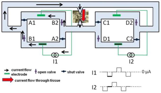
To eliminate DC current flow interruptions we engineered the SDCS2, which used two SDCS systems in the arrangement shown in Figure 2 [1]. One system drives current through the tissue while the other closes all valves first and then opens the next set of valves in sequence. The intermediate step of closing all valves on the system undergoing valve transitions prevents unintended current shunts through either system.
Figure 2.
Two system design uses one system (driven by I1 shown) to drive the current through the tissue, while the second system (driven by I2) to switch the valve states without causing output current interruption. Adapted from [1].
In the system state shown in Figure 2, I1 drives the current through the tissue while I2 is shut off. In order to switch valves from open-to-closed and closed-to-open in the right system (I2) from the state depicted in Figure 3, we first close the D valves. Because C valves remain shut during this operation, closing D valves will not cause any interruption in current flow even if D valves are relatively slow to close or they do not close at the same instant. Next, we open C valves. This transition does not cause any interruption in current flow, because D valves are now closed. Finally, we transition current control to the right system (I2), and simultaneously shut off the left system (I1). Since this transition is electronic rather than mechanical, it is very fast and does not cause interruption in current flow. The procedure is then repeated for the left (I1) system, first closing B valves and then opening A valves, while the right (I2) system drives current through the tissue. In this way, SDCS2 avoids all valve transition artifacts, even when the valves are slow [1;11]
Figure 3.
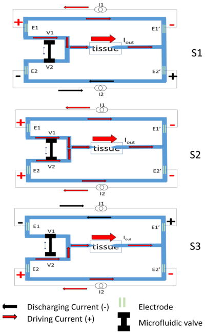
Conceptual three states of SDCS3 are shown. The system cycles from S1 to S2 to S3, and then back from S3 to S2 to S1 continually. During S1, I1 drives the current through the tissue via E1 and E1′ and I2 discharges E2, E2′ electrodes. During S3, I2 drives the current through the tissue and I1 discharges its electrodes. The tandem microfluidic valve is composed of two ports V1 and V2. This V1 and V2 change states during S2 and this transition results in initial opening of both valves and then closing the next one in sequence. The arrows pointing at the tissue represent microcatheter tubes filled with an electrolyte gel to allow ionic current flow to the neural targets.
In attempting to implement this design in a microfluidic substrate we encountered challenges centered on the reliability associated with developing eight identical valves, each powered by a separate actuator.
III. Methods
A. SDCS 3 Concept
The conceptual SDCS3 device construction is shown in Figure 3. The three panels show the varying states of the same device. The blue structures represent the microfluidic channels within the device, filled with an electrolyte. There are four metal electrodes, E1, E1′, E2, and E2′ submerged in the channels. E1 and E1′ are connected via one current source and E2 and E2′ are connected via a second current source. The two current sources I1 and I2 are designed to drive the current through the tissue in sequence, with one current source driving the current indicated in red through the tissue via one set of electrodes, and the other current source driving the current in the opposite direction indicated in black to discharge the electrodes. I1 drives the current from E1 to E1′, passing the current through the tissue in state S1, indicated by red arrows. The charge builds up on the electrode surfaces and needs to be discharged. This charge is dissipated from E1 and E1′ by changing the state of the device and reversing the current flow through I1 (black arrows) as shown in state S3. In these two states, I2 is driving the current in the opposite direction from I1, with S1 indicating the discharging of E2 and E2′ and S3 showing I2 driving the current through the tissue using E2 and E2′.
The microfluidic valve actuator is assumed to be non-ideal and thus take time to switch the state of the device. For this reason, the tandem valve with two ports, V1 and V2 are designed to transition from open-to-closed and closed-to-open in a way that will keep both ports partially open for a short duration during the transition in state S2. During this switch, both current sources I1 and I2 would be driving the current through the tissue. The amplitude of the current during the discharge phase following this transition period is always calculated to account for the total charge accumulated on the electrodes during the driving current phase as the integral of the driving current. To deliver the constant current to the tissue, the device changes states back and forth between S1 and S3 through S2.
D. SDCS 3 Model
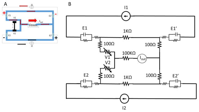
We modeled the SDCS 3 design in Simulink/Matlab as shown in Figure 4 using electrical components to represent ionic microfluidic channel impedances, electrode interfaces, and current sources. The tissue is modeled as a 100kΩ high impedance path due to the narrow-diameter micropipette conduits used to deliver iDC to the neural targets based on our previous experiments [2]. The valves are modeled as potentiometers with 1kΩ conduction path when they are fully open and 10MΩ when they are completely shut. The electrode contacts are modeled as capacitor/resistor parallel pair with a series resistor per Merrill et al. [5]. The values for these are 10μF in parallel with a 2MΩ resistor that are then in series with a 100Ω. The main assumption for the benefit of the model is that the metal electrodes will have sufficient surface area to avoid Faradaic reactions during device operation. Based on our previous experience with microfluidic valve operation, we assume that the action of closing and opening the tandem valve in state S2 will take 600ms. Iout is a measurement of the current delivered to the tissue.
Figure 4.
SDCS3 electrical equivalent component model.
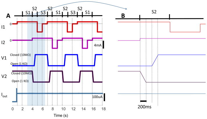
I1 and I2 positive driving currents are designed to overlap during the valve switch transition to maintain the current through the tissue during the transition. The negative discharge currents are designed to rapidly and completely drain the charge accumulated on the electrodes before the next state transition. The current sources are therefore set up to drive 1mA in the positive direction for four seconds and discharge at 4mA over one second, thus maintaining charge balance.
IV. Results
The model results are shown in Figure 5. Panel A shows 18 seconds of simulation. Panel B expands the time between 3 and 7 seconds to illustrate the details of the switching sequence time course. The bottom trace of the plot shows the current output to the tissue. Iout appears to be stable in the figure. Upon close examination we detected a 1% undulation in system output when both valves are open during S2.
Figure 5.
Modeling SDCS3 operation results. Panel A shows 18 seconds of operation. Panel B shows an expanded time scale for S2 state transition. The valve ports V1 and V2 transition in sequence by first opening V2, with both ports open for 200ms, and then closing V1. A single tandem valve is expected to accomplish this task using one actuator.
V. Conclusion
We presented a new concept for the construction of the Safe Direct Current Stimulator (SDCS). The goal of any SDCS is to deliver a stable ionic direct current to the neural targets while maintaining charge balance at the metal electrodes embedded within the device. We presented an electrical component model, designed to deliver 100μA to the neural targets. The model results suggest that this design can in principle convert alternating current pulses delivered to metal electrodes to ionic direct current. Current sources I1 and I2 are charge balanced with a stable device output within 1% variance.
The limitations of this model are that it assumes no variability in closed/open valve impedances, in the impedances of the microfluidic channels as well as in the ionic path through the tissue. Any of these variances will clearly affect system output Iout. For this reason, while we believe that the basic structure of the design is sound, a control system would need to be designed to monitor system output, and allow the current sources to compensate for any output irregularities. This control system would adjust the current drivers during the driving phase, integrate the output to determine the exact charge delivered to the electrodes during this time, and during the discharge phase adjust the discharge amplitude to account for the total accumulated charge.
The key features of this new design is that the number of actuators is reduced from 8 in SDCS2 to 1 in the new design and the number of valves is reduced from 8 independent valves to one tandem valve. Because the valve actuator will only need to function once every half-cycle to maintain system state, the amount of energy required to operate the mechanical valve is reduced from the need to operate average of 6 valves at the same time in SDCS2 to 0.5 duty cycle on one valve, resulting in a factor of 12 improvement in energy consumption. Additional improvement could be made by making the tandem valve bi-stable so the energy applied to the system would only be necessary to transition between S1 and S3, rather than using energy to maintain one system state.
Acknowledgments
Research supported by NIHR01NS092726, MedEl Corporate Grant
I would like to thank Dr. Andreas Andreou for challenging the reliability assertions of the original system design.
References
- 1.Fridman GY, Della Santina CC. Safe direct current stimulator 2: concept and design. Conf Proc IEEE Eng Med Biol Soc. 2013;2013:3126–9. doi: 10.1109/EMBC.2013.6610203. vol. Conf Proc IEEE Eng Med Biol Soc.2013;2013:3126–9. doi: 10.1109/EMBC.2013.6610203. Sept.2013. [DOI] [PMC free article] [PubMed] [Google Scholar]
- 2.Fridman GY, Della Santina CC. Safe direct current stimulation to expand capabilities of neural prostheses. IEEE Trans Neural Syst Rehabil Eng. 2013 Mar;21(2):319–328. doi: 10.1109/TNSRE.2013.2245423. [DOI] [PMC free article] [PubMed] [Google Scholar]
- 3.Guenther T, Lovell NH, Suaning GJ. Bionic vision: system architectures: a review. Expert Rev Med Devices. 2012 Jan;9(1):33–48. doi: 10.1586/erd.11.58. [DOI] [PubMed] [Google Scholar]
- 4.Wilson BS, Dorman MF. Cochlear implants: a remarkable past and a brilliant future. Hear Res. 2008 Aug;242(1–2):3–21. doi: 10.1016/j.heares.2008.06.005. [DOI] [PMC free article] [PubMed] [Google Scholar]
- 5.Merrill DR, Bikson M, Jefferys JGR. Electrical stimulation of excitable tissue: design of efficacious and safe protocols. Journal of Neuroscience Methods. 2005;141(2) doi: 10.1016/j.jneumeth.2004.10.020. [DOI] [PubMed] [Google Scholar]
- 6.Robblee L, Rose T. Electrochemical guidelines for selection of protocols and electrode materials for neural stimulation. 2003 [Google Scholar]
- 7.Rose TL, Robblee LS. Electrical-Stimulation with Pt Electrodes. 8. Electrochemically Safe Charge Injection Limits with 0.2 Ms Pulses. Ieee Transactions on Biomedical Engineering. 1990;37(11) doi: 10.1109/10.61038. [DOI] [PubMed] [Google Scholar]
- 8.Kilgore KL, Bhadra N. High frequency mammalian nerve conduction block: simulations and experiments. Conf Proc IEEE Eng Med Biol Soc. 2006;1:4971–4974. doi: 10.1109/IEMBS.2006.259254. [DOI] [PubMed] [Google Scholar]
- 9.Goldberg JM, Smith CE, Fernandez C. Relation between discharge regularity and responses to externally applied galvanic currents in vestibular nerve afferents of the squirrel monkey. Journal of Neurophysiology. 1984;51(6):1236–1256. doi: 10.1152/jn.1984.51.6.1236. [DOI] [PubMed] [Google Scholar]
- 10.Bhadra N, Kilgore KL. Direct current electrical conduction block of peripheral nerve. IEEE Trans Neural Syst Rehabil Eng. 2004 Sep;12(3):313–324. doi: 10.1109/TNSRE.2004.834205. [DOI] [PubMed] [Google Scholar]
- 11.Fridman GY, Kararo E, Kuo B, Zheng Y, Della Santina CC. Safe Direct Current Stimulator Microfluidic Design for Vestibular Prosthesis. ARO Midwinter Meeting; 2014. [Google Scholar]


