Abstract
The use of magnetic resonance imaging (MRI) for guiding robotic surgical devices has shown great potential for performing precisely targeted and controlled interventions. To fully realize these benefits, devices must work safely within the tight confines of the MRI bore without negatively impacting image quality. Here we expand on previous work exploring MRI guided robots for neural interventions by presenting the mechanical design and assessment of a device for positioning, orienting, and inserting an interstitial ultrasound-based ablation probe. From our previous work we have added a 2 degree of freedom (DOF) needle driver for use with the aforementioned probe, revised the mechanical design to improve strength and function, and performed an evaluation of the mechanism’s accuracy and effect on MR image quality. The result of this work is a 7-DOF MRI robot capable of positioning a needle tip and orienting it’s axis with accuracy of 1.37 ± 0.06mm and 0.79° ± 0.41°, inserting it along it’s axis with an accuracy of 0.06 ± 0.07mm, and rotating it about it’s axis to an accuracy of 0.77° ± 1.31°. This was accomplished with no significant reduction in SNR caused by the robot’s presence in the MRI bore, ≤ 10.3% reduction in SNR from running the robot’s motors during a scan, and no visible paramagnetic artifacts.
I. INTRODUCTION
Stereotactic neurosurgery is a procedure in which a 3-dimensional image of the brain is used to guide the precise placement of needles or probes for therapeutic or diagnostic purposes. The positioning and insertion of these probes is typically conducted manually with the help of a stereotactic frame following registration from images taken using a CT or MRI scanner. Recently, work has been conducted towards using devices to help perform stereotactic procedures with the patient inside the MRI bore. For example, the commercially available ClearPoint® System by MRI Interventions, Inc. enables probe manipulation inside the MRI using a manually actuated Bowden cable system. Similarly, the NeuroBlate® by Monteris Medical Corp. uses a cable-actuated 2-DOF needle driver to insert and rotate a probe, with an added motorized motion.
The ability to manipulate probes with the patient inside the MRI bore opens up unique possibilities such as guiding procedures based on real-time MRI imaging. One application of procedures guided by real-time MRI is to provide precise thermal doses to deep brain tumors using needle-based ablative methods. The ability to generate temperature maps using shifts in the MRI phase mapping is well known [1][2]. Combining this mapping with a directional ablation pattern, such as has been demonstrated using sectored ultrasound [3][4] and laser based methods [5], can allow for feedback-guided targeting of arbitrarily-shaped ablation regions resulting in minimal damage to healthy tissue.
While motion of a probe along and about its axis is important for guided application of therapies, initial orientation and placement of the probe in a target region can also benefit from robotic approaches. MRI robots designed for prostate interventions have shown high targeting precision in the past [6]–[9] and Ho et al. has shown the ability to control a dexterous SMA surgical robot inside of an MRI bore [10]. Other work has explored MRI-guided neurosurgery within the scanner room without performing procedures in the scanner bore during live imaging [11]. Expanding on this previous work and combining robotic probe alignment with robotic in-bore manipulation has the potential to streamline stereotactic procedures and improve accuracy.
To enable future contributions in this area of stereotactic procedures guided by feedback from live MR imaging, in this work we present the mechanical design and validation of a 7 degree of freedom (DOF) MRI compatible stereotactic neurosurgery robot. This work represents a fully re-designed and updated version of a 5-DOF robotic stereotactic frame previously presented by Li et al. [12] which was used for initial phantom studies. The contributions of this work are an updated kinematic design, the addition of a 2-DOF end effector for inserting and orienting a needle-based sectored ultrasound ablation probe, re-design of all mechanical components for improved robustness, a comprehensive evaluation of the robot’s accuracy based on ISO-9328 standard, and an evaluation of the robot’s MRI compatibility. This work was carried out in preparation for pre-clinical animal studies which are currently in progress.
II. MECHANICAL DESIGN
The robot is designed as a remote center of motion (RCM) mechanism with 7-DOF. These 7-DOF can be grouped into 3 modules each with an independent function:
A 3-DOF Cartesian module, with translations labeled tx, ty, and tz in Fig. 2, for positioning the robot’s RCM point at a target location.
A 2-DOF remote center orientation module, with rotations labeled Rx and Ry in Fig. 2, which aligns the axis of the needle or probe to pass through a burr hole (typically drilled by the surgeon prior to placing the patient in the scanner bore).
A 2-DOF needle driver module, with translation labeled Probe Insertion and rotation labeled Rz in Fig. 2, for inserting the needle or probe to a desired depth and orientating probes with directionally applied therapies.
Fig. 2.
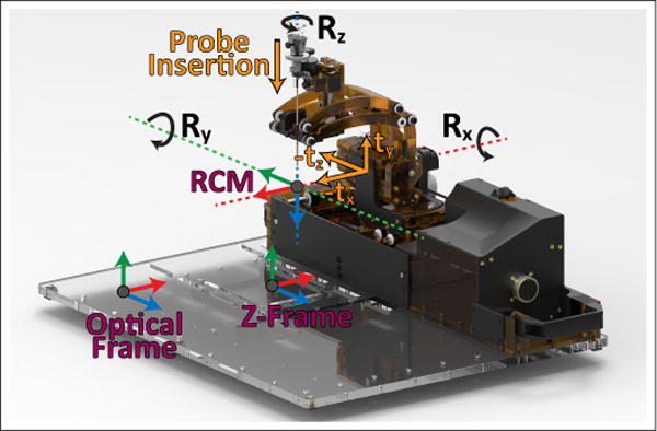
The registration frames and motions of the developed robot. A fiducial z-frame placed under the robot’s base is used for MRI registration and an optical frame is used for accuracy assessment registration.
Each of these modules is either new or has been considerably updated from our previous conceptual prototype [12]. The changes made, and the motivations for making these changes, are as follows: The 3-DOF Cartesian module has been re-designed with a mechanism which couples the motions ty and tz allowing for a 45mm lower workspace which reduces collisions between the ablation probe and MRI bore. This module also now uses lead screws driven by rotary ultrasonic motors as opposed to linear Piezo LEGS® motors, this is a less fragile design which can be geared to overcome the resistance created by cabling and cooling lines needed for an ablation probe. The 2-DOF needle driver module is a new addition which allows for in-bore probe manipulation to orient and target directional therapies. Furthermore, these two modules, along with the 2-DOF RCM module, have been redesigned to be machined from the durable and rigid thermoplastic Polyetherimide (PEI). The result of this is a stronger, more reliable, and more rigid device than our previous rapid-prototyped designs. The specifics of each of these new designs follows.
The Cartesian module uses a parallel linkage mechanism which results in coupling of motions ty and tz. This mechanism, whose kinematics are shown in Fig. 5, has two prismatic joints which are moved along a pair of 12mmϕ anodized aluminum linear-rails with plastic bearings (AWM-12 and RJUM-21-12, igus Inc., East Providence, RI, USA) by a pair of 10mmϕ aluminum lead screws with plastic nuts (PTGSG-10x2-01-R-AL and WSRM-2215TR10x2, igus Inc.). The position of each joint is measured by quadrature encoders (EM1-0-500-N, US Digital, Vancouver, Washington) with a resolution of 500 lines per inch (0.013mm/count). This parallel linkage design has been adapted from an MRI guided robot used in clinical trials of prostate biopsies [13]. This design takes advantage of the spacious MRI bore length and restrictive MRI bore height and width. It has been updated from the design presented in [13] to use two lead screws which are not co-axial and each run the entire length of the linear rails, allowing for expanded motion of the robot along tz. The final translation of the Cartesian module, tx, is a decoupled motion driven directly by lead screw. Two lead screws synced together by a timing belt are used, one on either end of the linear rails used for the tz/ty prismatic joints. The 3 axes in the Cartesian module are actuated by 3 piezoelectric ultrasonic motors (USR30-NM, Fukoku Co., Ageo-shi, Japan).
Fig. 5.
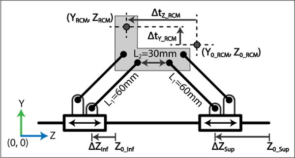
The kinematics of the parallel linkage mechanism used for coupled vertical translation and translation along the MRI bore.
The rotation Rx of the 2-DOF remote center orientation module is a pure revolute motion. The axis is actuated by an ultrasonic motor (USR45-NM, Fukoku Co.) through a 4.11:1 ratio of brass and aluminum gearing. The rotation Ry is remotely located at a point which intersects Rx using a parallel linkage mechanism whose kinematics are shown in Fig. 6. A single joint of the linkage is actuated using an ultrasonic motor (USR30-S4N, Shinsei Corp., Tokyo, Japan) through a 60:1 gear reduction. The parallel constraints of the mechanism directly map this rotation to the RCM point. This design allows for orienting our end effector over the patient’s head using a compact mechanism which places the motor in its base as opposed to throughout its links; moving the actuators away from the imaging region is done to minimize image quality degradation. Rotation angles for Rx and Ry are measured directly by quadrature encoders (EM1-0-1250-N, US Digital) with 1250CPR resolution (0.072°/count) placed after their gear reductions to avoid measurement errors related to backlash.
Fig. 6.
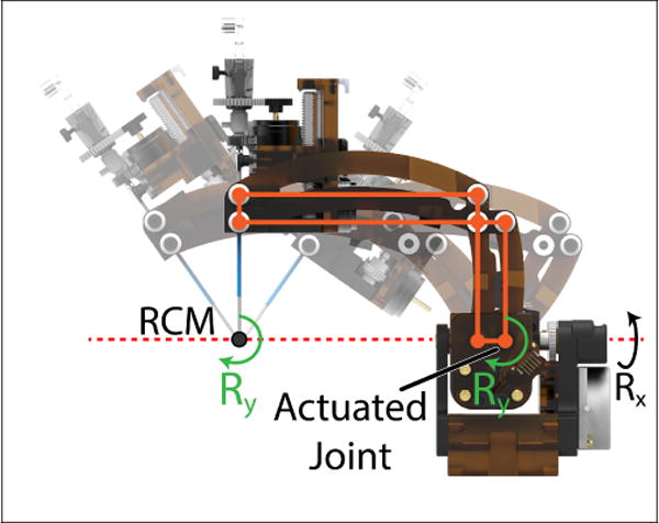
A side view of the 2-DOF orientation module used to orient the probe using a parallel linkage mechanism. The rotation Ry, produced at the actuated joint of the linkages, is offset to a point which intersects the rotation Rx due to the parallel constraints imposed by the mechanism.
The 2-DOF needle driver module has prismatic joint probe insertion driven along an aluminum linear rail (DryLin TK-04-12 TWE, igus Inc.) by an aluminum lead screw and plastic nut (PTGSG-10x2-01-R-AL and WSRM-2215TR10x2, igus Inc.). For rotation Rz, a plastic gear is attached to the probe which mates to the rotation motor. The probe assembly, Rz drive gear, a cannula, and a depth stop are made to be sterilized and attached by the surgeon following draping of the robot, these components can be seen in Fig. 4. Insertion and rotation are driven by ultrasonic motors (USR30-S4N, Shinsei Corp.) with orientation of Rz measured using a 1250CPR encoder (EM1-0-1250-N, US Digital) placed before the gearing and probe insertion measured directly using a reflective encoder with 300 lines per inch resolution (0.021mm/count).
Fig. 4.
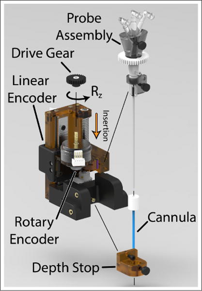
Exploded view of the needle driver assembly indicating parts removable for sterilization. During a surgical procedure, the needle driver and robot arm are covered in a sterile drape. A sterile pack containing the probe assembly, Rz drive gear, depth stop, and cannula is provided to the surgeon and attached over top the sterile drape.
A fiducial frame, referred to as a Z-frame, is placed underneath the base platform for registration of the robot to the MRI scanner’s coordinate frame. Automated detection and registration with this type of frame has been demonstrated with translational accuracy of 1.00 ± 0.73 mm and angulation error of 1.41° ± 1.06° [14]. The frame is made of 3 z-shaped sets of 3 fiducial markers each (MR-SPOTS #121, Beekley Medical) placed inside a 3D printed frame attached beneath the robot base. Attachment points for reflective optical tracking markers were also included on the precisely machined base platform for bench-top calibration and accuracy assessment. These two reference frames are parallel to each other with known spatial offsets and are shown in Fig. 2
A. Kinematics
The range of motions for the axes in Fig. 2 are quantified in Table I. These ranges resulted from the constraints of the MRI bore and patient position seen in Fig. 1, conclusions from a previous 5-DOF neurosurgery robot by Li et al. [12], and from conversations with clinical advisors. As mentioned previously, with the exception of ty, tz, and Ry, all motions on the robot are either pure prismatic or revolute joints with trivial kinematic representations. Likewise, the motion of Ry can be considered a pure revolute joint acting at the RCM point. Fig. 6 demonstrates visually how the parallel constraints of the robot arm, in combination with the axis Rx being collinear with one of the mechanism’s parallel sides, causes this behavior.
TABLE I.
Joint Space Kinematic Specifications: Range of motion measured from home position.
| Axis | Motion | Min Value | Max Value | Units |
|---|---|---|---|---|
|
| ||||
| 1 | tx | −37.5 | 0 | mm |
| 2 | ty | 0 | 44.23 | |
| 3 | tz | −86 | 0 | mm |
| 3 | tz2 | −143 | 57 | mm |
| 4 | Rx | −90 | 0 | deg |
| 5 | Ry | −37.2 | 30.6 | deg |
| 6 | Rz | – | Continuous | deg |
| 7 | Pi | −40 | 0 | mm |
Fig. 1.
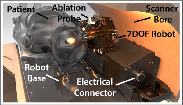
Our neuro-surgery robot in a 60cm diameter MRI bore with patient placed in the supine position. A base platform is attached to the MRI bed onto which the patient’s head is affixed. The robot is slid onto the platform and connected to it’s controller using a single 144 conductor cable.
The ty and tz coupled motion of the Cartesian module’s parallel mechanism are explained by the following forward kinematics derived based on Fig. 5:
| (1) |
| (2) |
| (3) |
| (4) |
Variables with subscript 0 indicate the initial home position of the robot. Y0_RCM and Z0_RCM are measured explicitly using the procedure described in Section III of this paper. Eqs. 1–3 describe how the height, YRCM, is determined by the separation between the two actuated prismatic joints of the mechanism. Eq. 4 determines tz translation of the RCM point of the robot by the motion of the prismatic joints, ∆zsup and ∆zinf. Due to the motion of the prismatic joints relative to each other the range of motion, tz, is dependent on height, ty. In Table I, tz is the maximum translation when the parallel mechanism is at ty = 0 (the bottom of vertical travel); tz2 is the maximum translation when ty = 44.23mm (the top of vertical travel).
III. EXPERIMENTAL VALIDATION
To verify that the developed mechanical system is ready for pre-clinical trials, validation of the robot’s accuracy, repeatability, and it’s effect on image quality were performed. Accuracy assessment was conducted outside of the MRI as greater measurement resolution could be achieved with non-MR measurement systems. Assessment of the robot’s effect on image signal-to-noise ratio (SNR) and distortion was conducted inside the MRI using a recently developed MRI phantom.
A. Accuracy Assessment
Accuracy assessment was conducted using a 6-camera optical tracking system (Optitrack Flex 13, Natural Point Inc., Corvallis, Oregon). Camera calibration was performed immediately prior to testing with a mean 3D re-projection error of 0.2mm or less. A 3-marker tracking tool was constructed to fit on the robot in place of the ablation probe. The tool included a 220mm long 6.5mmϕ aluminum rod with a straightness of 0.018mm placed along the probe axis with 6.5mm reflective marker balls attached concentrically at either end. This rod was considered as ground-truth for the probe axis. A third and final marker ball was attached to the tool offset from probe axis by 40mm. Three additional reflective balls were attached at precise positions on the robot base to determine the ground plane as shown in Fig. 7.
Fig. 7.
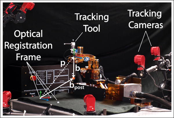
Accuracy assessment testing. A three marker tracking tool is used in place of the ablation probe with three additional markers attached to the robot base for registration. The robot base is clamped to an optical tracking table to ensure flatness. Vectors p, btip, and bpost are used to calculate the position of the RCM point relative to the optical frame.
Since the robot is designed as an RCM mechanism, localization of the RCM point relative to the robot base was performed along with an assessment of the RCM’s quality using a pivot calibration described in [15]. This procedure was conducted with motions tx, ty, and tz at their home positions. The robot’s rotation Rx was positioned in 10° increments while the rotation Ry was swept back and forth through its range of motion. By measuring the tracking tool position, p = [px py pz], and rotation matrix, Rtool, the Ry sweep defines a 3x1 vector (btip) from the tracking tool frame to the RCM point along with a 3x1 vector (bpost) from optical frame to the RCM point (Fig. 7). Eq. 5 and Eq. 6 explains the procedure:
| (5) |
| (6) |
The rows of matrix [Rtool −I] and −p are expanded for n number of data points. A pseudo-inverse of Eq. 6 gives the least squares best fit for the vectors btip and bpost. With these values, we can calculate the pivot calibration RMS error by subtracting the measured tool position from the expected position across all sample points.
Accuracy and repeatability were assessed based on the ISO 9283 standard for manipulating industrial robots [16] under section pose accuracy and repeatability. The tests were reported as mean error μ for accuracy and 3 times the standard deviation 3σ for repeatability. Mean error is the distance between the mean of n data points and the target point. Position assessment was done by visiting five targets (P1, P2, P3, P4, P5) 30 times each in the order: P5 through P1. These positions were chosen as to reside on a plane diagonally bisecting the maximum workspace and as defined by the ISO standard, these points are labeled in Fig. 10. For orientation, similar methods were used to define and test five targets (O1, O2, O3, O4, and O5) where Oi = [Ry, Rx]. During the orientation test, the robot position is placed at P1. Rotation axis Rz and insertion axis Pi were tested independently by similarly choosing 5 target points that represents the workspace.
Fig. 10.
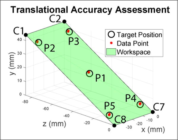
Assessment of the positional accuracy of the inserted probe tip. The green plane diagonally bisects the workspace and five target positions(P1, P2, P3, P4, and P5) are selected on that plane based on the ISO9283 standard. These positions are visited 30 times each.
B. MRI Compatibility
To assess the robot’s effect on MRI imaging, tests of signal-to-noise ratio (SNR) and distortion were carried out using a Philips Achieva 3T scanner at the University of Massachusetts (UMASS) Medical School in Worcester, Ma. Image quality was assessed using a 90mm × 90mm × 60mm gelatin filled phantom (mixed 15:1 water:gelatin by weight) similar to the one used in [17]. The top 45mm of the phantom is a homogeneous region to assess SNR while the bottom 15mm is a grid of 12.5mm × 12.5mm squares to assess distortion. Tests were conducted in 4 different conditions:
Baseline: The robot and its controllers are not present in the MRI room.
Robot Present: The robot is placed inside the MRI bore and connected to its controller. The controller is powered off.
Robot Powered: The robot is present inside the MRI bore, is connected to its controller, and its controller is powered on. The motors are not moving.
Robot Moving: The robot is present inside the MRI bore, is connected to its controller, and the needle driver motors, those for Rz and Probe Insertion, are running continuously.
The phantom was placed in the robot’s targeting region and was not moved between testing conditions. When present in the MRI bore, it was positioned with axes Rx, Rz, tx, and ty in the middle of their respective ranges of motions, probe insertion was placed fully inserted, and tz was placed close to its home position. This configuration is representative of where the robot would be during a typical procedure.
For each of these conditions, image quality was assessed using two standard imaging sequences; they were selected as standard T1 and T2-weighted sequences used for American College of Radiology (ACR) quality control tests. The parameters used for these scans are shown in Table II. Images were acquired using Philips SENSE Flex-M coils positioned as shown in Fig. 8. T1 and T2 scans were repeated twice for each condition, except for the baseline where they were repeated three times.
TABLE II.
Image Quality Tests: Scan Sequence Parameters
| Sequence | TE (ms) | TR (ms) | Slice Thickness (mm) | Bandwidth (hz/pixel) | Image Size (pixels) | FOV (mm) |
|---|---|---|---|---|---|---|
| T1 ACR | 20 | 500 | 3.0 | 218 | 176X176 | 150 |
| T2 ACR | 80 | 2000 | 3.0 | 218 | 176X176 | 150 |
Fig. 8.
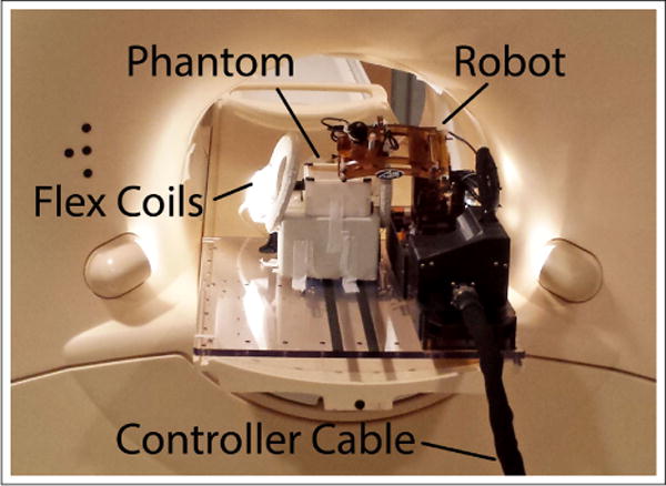
Testing setup for noise and distortion testing.
SNR was calculated in a similar manner as for the device in [9], [17] based on NEMA standard [18]. Described briefly, in each image slice, s, containing the homogeneous section of the phantom a region of interest (ROI) is selected within said homogeneous section. Given two scan sequences, I and J, taken under the same test conditions a difference image is calculated for each slice by subtracting the pixel intensities, p, within the ROI of image I from those of the same ROI in image J. The noise, N, for a given slice is calculated based on the standard deviation of this difference image using Eq. 7, where u and v are the pixel indices which span the read encode and phase encode directions of the ROI [17]. Signal is calculated as the mean pixel intensity from within the ROI of both scan sequences as shown in Eq. 8. The SNR of a given slice is calculated by Eq. 9.
| (7) |
| (8) |
| (9) |
For each test condition, SNR values across all slices of the homogeneous region were compared to the first baseline condition using a paired t-test in analytics software IBM SPSS to determine if a statically significant change in the mean had occurred.
Distortion effects are also important to analyze due to the potential for induced eddy currents and paramagnetic artifacts from the robot’s structure. To quantify any warping of the image, cross sections of the grid region were thresholded and the centroids of the individual squares found via image processing in OpenCV. The positions of these centroids in baseline and robot moving conditions are then compared to quantify any skewing of the image.
IV. RESULTS
A. Accuracy
At the robot home position, the pivot calibration calculated the RCM point RMS error and position, bpost, as referenced from the optical tracking frame to be:
Fig. 9 illustrates the collected pivot calibration tool positions, p, along with projections of the probe axis pointing to the derived RCM point.
Fig. 9.
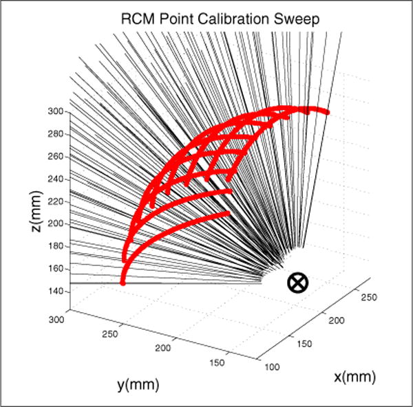
Calibration of the RCM point using sweeping motion of the robot’s pitch axis at 10° increments of the robot’s yaw axis. The RCM point is determined using a pivot calibration.
Table III summarizes the mean RMS error, μp, and standard deviation for position accuracy of each target points P1 through P5 of the ISO 9283 standard.
TABLE III.
Accuracy Test Results of the 3-DOF Cartesian Module Units: mm
| Target Point | Target Location | μp | σp | μtx | σtx | μty | σty | μtz | σtz | ||
|---|---|---|---|---|---|---|---|---|---|---|---|
| tx | ty | tz | |||||||||
| P1 | −33.75 | 4.42 | −8.6 | 1.02 | 0.03 | 0.22 | 0.05 | 0.66 | 0.03 | −0.75 | 0.03 |
| P2 | −3.75 | 4.42 | −8.6 | 1.30 | 0.02 | 0.24 | 0.03 | 0.13 | 0.02 | −1.27 | 0.02 |
| P3 | −3.75 | 39.80 | −77.40 | 1.37 | 0.01 | 0.20 | 0.02 | 0.08 | 0.01 | −1.35 | 0.01 |
| P4 | −33.75 | 39.80 | −77.40 | 0.57 | 0.04 | 0.07 | 0.04 | 0.54 | 0.06 | −0.16 | 0.02 |
| P5 | −18.75 | 22.11 | −43 | 0.54 | 0.04 | 0.06 | 0.03 | 0.54 | 0.06 | −0.04 | 0.02 |
μp is the total x-y-z position error in the global coordinate frame. The largest μp is 1.37mm, at P3, which is the furthest away from the home position in the tz direction. By translating along tz (P5-P1-P3), a systematic error in positioning can be deduced. The standard deviation (σp) is better than the accuracy for all points P5 through P1. The largest standard deviation is 0.04mm at P4 and P5. Mean position errors and standard deviations for the individual axis tx, ty, and tz were taken as μtx, σtx, μty, σty, μtz, and σtz.
Table IV summarizes the orientation axis accuracy test results. The largest orientation mean error for Ry (μRy) and Rx (μRx) is 0.47° and −0.79° respectively. The largest orientation standard deviation for Ry (σRy) and Rx (σRx) is 0.23° and 0.20°.
TABLE IV.
2-DOF Orientation Module Accuracy Units: degrees
| Target Points | Target Location | μRy | σRy | μRx | σRx | |
|---|---|---|---|---|---|---|
| Ry | Rx | |||||
| O1 | −3.28 | −45 | 0.06 | 0.14 | −0.22 | 0.14 |
| O2 | 23.82 | −9 | 0.47 | 0.21 | −0.40 | 0.17 |
| O3 | −30.38 | −9 | −0.19 | 0.16 | 0.13 | 0.20 |
| O4 | −30.38 | −81 | −0.26 | 0.23 | −0.11 | 0.12 |
| O5 | 23.82 | −81 | −0.10 | 0.08 | −0.79 | 0.14 |
Table V summarizes the needle driver rotation axis accuracy test results. The largest rotation mean error (μRz) is 0.77°. The largest rotation standard deviation (σRz) is 0.43°. Reduced repeatability in this axis was expected since the need for the surgeon to easily insert the probe and align its gear resulted in a looser mesh between gears.
TABLE V.
Needle Driver Rotation Accuracy Units: degrees
| Target Points | Target Location Rz | μRz | σRz |
|---|---|---|---|
|
| |||
| R1 | −90 | 0.77 | 0.43 |
| R2 | −45 | 0.62 | 0.22 |
| R3 | 0 | 0.48 | 0.15 |
| R4 | −45 | 0.16 | 0.09 |
| R5 | 90 | −0.19 | 0.19 |
Table VI summarizes the insertion axis (Pi) accuracy test results. The highest insertion mean error (μPi) is −0.06mm. The highest insertion standard deviation (σPi) is 0.05mm. Unlike the standard 30 iterations, only 10 iterations were taken for the insertion test.
TABLE VI.
Needle Driver Insertion Accuracy Units: mm
| Target Points | Target Location Pi | μPi | σPi |
|---|---|---|---|
|
| |||
| I1 | 0 | 0.01 | 0.05 |
| I2 | 8.5 | −0.03 | 0.02 |
| I3 | 17 | −0.03 | 0.03 |
| I4 | 25.5 | −0.03 | 0.03 |
| I5 | 34 | −0.06 | 0.02 |
B. Image Quality
Compared to the first baseline condition, SNR in T1 weighted scans showed no significant change in the second baseline condition or the robot present condition (p = 0.495 and p = 0.82 respectively). Statistically significant changes in SNR were seen with the robot powered on, (p = 0.04) causing a reduction in mean SNR of 2.9%, and with the robot moving, (p = 0.00) with a mean reduction of 10.3%.
SNR in T2 weighted scans showed a near significant change between baseline scans (p = 0.06). This was caused by a slight shift in the phantom position between image sets used in the noise calculation of Eq. 7 by a couple millimeters. This issue did not occur in any other condition. No statistical difference was seen in the robot present and robot powered on conditions (p = 0.90 and p = 0.44 respectively). A statistically significant decrease in SNR was observed when the motors were moving (p = 0.02) with an average reduction of 6.7% over the first baseline scan.
Finally MRI images were checked for signs of distortion or shadows caused by the presence of the robot inside the MRI machine. Visual inspection showed no warping of the images or blacked-out regions. Representative images from the T1-weighted scan are shown in Fig. 12. Regions with casting defects in the phantom which influenced the centroid calculation, such as the bottom left corner in Fig. 11 were excluded. The mean distance between centroids in the images with and without the robot present were found to be on average 0.1mm with a maximum deviation of 0.2mm indicating minimal to no distortion.
Fig. 12.
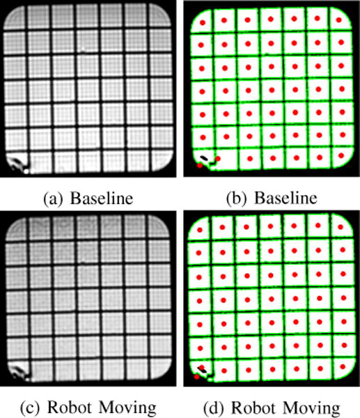
Representative example of images taken with and without the robot present. On left are T1-weighted MRI images, on the right are thresholded images which show the centroid of each grid space.
Fig. 11.
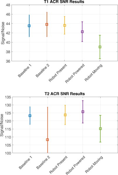
SNR with ±σ error bars. Note: a shift of the phantom between imaging sequences of the T2 Baseline2 condition resulted in large variance and artificially low SNR.
V. DISCUSSION
We have presented the design and mechanical validation of a 7-DOF neurosurgery robot for the alignment and in-bore manipulation of needle-based therapies. This work was conducted to transition our initial prototypes used in phantom studies to a device capable of beginning pre-clinical animal trials. Design elements such as the parallel linkage mechanism used in our Cartesian module were the result of a need for a strong but compact vertical lift mechanism. This form factor takes advantage of the limited space between the patient and MRI bore, combining two axes of motion and providing a wide base for supporting the orientation arm and a newly developed needle driver. The needle driver is capable of precisely positioning and orienting the needle or probe, allowing for in-bore manipulation. The robot is constructed with considerations for sterilization and draping procedures, largely made of polyetherimide plastics and other materials compatible with autoclave, gas, and desiccation sterilization. Bench-top experiments were conducted demonstrating high repeatability for probe tip position, orientation, rotation, and insertion. The systematic positional errors of ≤ 1.37mm could be reduced by applying a correction offset in future work; thus making the accuracy closer to the repeatability.
Tests in the MRI showed minimal effect on images under most test conditions. No evidence of paramagnetic artifacts, such as distorted or blacked-out regions, were seen in any of the cases. Tests of SNR showed no reduction caused by the robot’s presence and minimal (< 3%) reduction when powered on. Reductions in SNR were seen in scans with the needle driver running (≤ 10.3%), however, this compares favorably with previous robots using piezoelectric actuators [12] and off-the-shelf use of piezoelectric actuators [19]. A focus on well-shielded cabling and filtered DC-power lines likely contributed to these improvements.
Overall this work provides a hardware platform for expanded research into live MRI-guided probe or needle based neural interventions. The focus of this paper has been on interstitial ultrasound ablation, however, other therapies such as laser-based ablative devices and deep brain stimulation electrode placement could also benefit from precise needle placement using a robotic stereotactic frame.
Fig. 3.
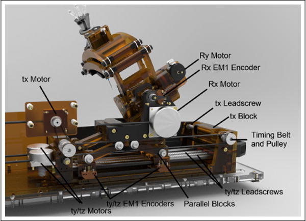
Cutaway-view showing The main mechanical parts of the 3-DOF Cartesian module and 2-DOF orientation module.
Acknowledgments
This work was supported by a grant from the National Institute of Health, R01 CA166379
References
- 1.Ishihara Y, Calderon A, Watanabe H, Okamoto K, Suzuki Y, Kuroda K, Suzuki Y. A precise and fast temperature mapping using water proton chemical shift. Magnetic Resonance in Medicine. 1995;34(6):814–823. doi: 10.1002/mrm.1910340606. [DOI] [PubMed] [Google Scholar]
- 2.Peters RD, Henkelman RM. Proton-resonance frequency shift mr thermometry is affected by changes in the electrical conductivity of tissue. Magnetic resonance in medicine. 2000;43(1):62–71. doi: 10.1002/(sici)1522-2594(200001)43:1<62::aid-mrm8>3.0.co;2-1. [DOI] [PubMed] [Google Scholar]
- 3.Burdette EC, Banovac F, Diederich CJ, Cheng P, Wilson E, Cleary KR. Conformal needle-based ultrasound ablation using em-tracked conebeam ct image guidance. 2011;9:790 107–790 107. [Online]. Available: http://dx.doi.org/10.1117/12.876550. [Google Scholar]
- 4.Ghoshal G, Salgaonkar V, Wooton J, Williams E, Neubauer P, Frith L, Komadina B, Diederich C, Burdette EC. Ex-vivo and simulation comparison of multi-angular ablation patterns using catheter-based ultrasound transducers. 2013;11:85 840Y–85 840Y. [Online]. Available: http://dx.doi.org/10.1117/12.2008255. [Google Scholar]
- 5.Stafford RJ, Fuentes D, Elliott AA, Weinberg JS, Ahrar K. Laser-induced thermal therapy for tumor ablation. Critical Reviews in Biomedical Engineering. 2010;38(1) doi: 10.1615/critrevbiomedeng.v38.i1.70. [DOI] [PubMed] [Google Scholar]
- 6.Su H, Shang W, Cole G, Li G, Harrington K, Camilo A, Tokuda J, Tempany CM, Hata N, Fischer GS. Piezoelectrically actuated robotic system for mri-guided prostate percutaneous therapy. IEEE/ASME Transactions on Mechatronics. 2015;20(4):1920–1932. doi: 10.1109/TMECH.2014.2359413. [DOI] [PMC free article] [PubMed] [Google Scholar]
- 7.Tokuda J, Song S-E, Fischer GS, Iordachita II, Seifabadi R, Cho NB, Tuncali K, Fichtinger G, Tempany CM, Hata N. Preclinical evaluation of an mri-compatible pneumatic robot for angulated needle placement in transperineal prostate interventions. International journal of computer assisted radiology and surgery. 2012;7(6):949–957. doi: 10.1007/s11548-012-0750-1. [DOI] [PMC free article] [PubMed] [Google Scholar]
- 8.Muntener M, Patriciu A, Petrisor D, Schar M, Ursu D, Song DY, Stoianovici D. Transperineal prostate intervention: Robot for fully automated mr imagingsystem description and proof of principle in a canine model 1. Radiology. 2008;247(2):543–549. doi: 10.1148/radiol.2472070737. [DOI] [PMC free article] [PubMed] [Google Scholar]
- 9.Stoianovici D, Kim C, Srimathveeravalli G, Sebrecht P, Petrisor D, Coleman J, Solomon SB, Hricak H. Mri-safe robot for endorectal prostate biopsy. IEEE/ASME Transactions on Mechatronics. 2014;19(4):1289–1299. doi: 10.1109/TMECH.2013.2279775. [DOI] [PMC free article] [PubMed] [Google Scholar]
- 10.Ho M, McMillan AB, Simard JM, Gullapalli R, Desai JP. Toward a meso-scale sma-actuated mri-compatible neurosurgical robot. IEEE Transactions on Robotics. 2012 Feb;28(1):213–222. doi: 10.1109/TRO.2011.2165371. [DOI] [PMC free article] [PubMed] [Google Scholar]
- 11.Sutherland GR, Latour I, Greer AD. Integrating an image-guided robot with intraoperative mri. IEEE Engineering in Medicine and Biology Magazine. 2008 May;27(3):59–65. doi: 10.1109/EMB.2007.910272. [DOI] [PubMed] [Google Scholar]
- 12.Li G, Su H, Cole GA, Shang W, Harrington K, Camilo A, Pilitsis JG, Fischer GS. Robotic system for mri-guided stereotactic neurosurgery. IEEE Transactions on Biomedical Engineering. 2015;62(4):1077–1088. doi: 10.1109/TBME.2014.2367233. [DOI] [PMC free article] [PubMed] [Google Scholar]
- 13.Eslami S, Shang W, Li G, Patel N, Fischer GS, Tokuda J, Hata N, Tempany CM, Iordachita I. In-bore prostate transperineal interventions with an mri-guided parallel manipulator: system development and preliminary evaluation. The International Journal of Medical Robotics and Computer Assisted Surgery. 2015 doi: 10.1002/rcs.1671. [DOI] [PMC free article] [PubMed] [Google Scholar]
- 14.Tokuda J, Song S-E, Tuncali K, Tempany C, Hata N. Configurable automatic detection and registration of fiducial frames for device-to-image registration in mri-guided prostate interventions. International Conference on Medical Image Computing and Computer-Assisted Intervention Springer. 2013:355–362. doi: 10.1007/978-3-642-40760-4_45. [DOI] [PMC free article] [PubMed] [Google Scholar]
- 15.Yaniv Z. Which pivot calibration? 2015;9:941 527–941 527. [Online]. Available: http://dx.doi.org/10.1117/12.2081348. [Google Scholar]
- 16.Manipulating Industrial Robots – Performance Criteria and Related Test Methods. International Organization for Standardization Std. ISO 9283; 1998. [Google Scholar]
- 17.Stoianovici D, Jun C, Lim S, Li P, Petrisor D, Fricke S, Sharma K, Cleary K. Multi-imager compatible, mr safe, remote center of motion needle-guide robot. IEEE Transactions on Biomedical Engineering. 2017;(99):1–1. doi: 10.1109/TBME.2017.2697766. [DOI] [PMC free article] [PubMed] [Google Scholar]
- 18.Determination of Signal-to-Noise Ratio (SNR) in Diagnostic Magnetic Resonance Imaging. National Electrical Manufacturers Association Std; 2015. (NEMA MS 1-2008 (R2014)). [Google Scholar]
- 19.Fischer GS, Krieger A, Iordachita I, Csoma C, Whitcomb LL, Fichtinger G. Mri compatibility of robot actuation techniques– a comparative study. International Conference on Medical Image Computing and Computer-Assisted Intervention Springer. 2008:509–517. doi: 10.1007/978-3-540-85990-1_61. [DOI] [PMC free article] [PubMed] [Google Scholar]


