Abstract
Micro-electromechanical systems (MEMS) that rely on structural vibrations have many important applications, ranging from oscillators and actuators, to energy harvesters and vehicles for measurement of mechanical properties. Conventional MEMS, however, mostly utilize two-dimensional (2D) vibrational modes, thereby imposing certain limitations that are not present in 3D designs (e.g., multi-directional energy harvesting). 3D vibrational microplatforms assembled through the techniques of controlled compressive buckling are promising because of their complex 3D architectures and the ability to tune their vibrational behaviour (e.g., natural frequencies and modes) by reversibly changing their dimensions by deforming their soft, elastomeric substrates. A clear understanding of such strain-dependent vibration behaviour is essential for their practical applications. Here, we present a study on the linear and nonlinear vibration of such 3D mesostructures through analytical modeling, finite element analysis (FEA) and experiment. An analytical solution is obtained for the vibration mode and linear natural frequency of a buckled ribbon, indicating a mode change as the static deflection amplitude increases. The model also yields a scaling law for linear natural frequency that can be extended to general, complex 3D geometries, as validated by FEA and experiment. In the regime of nonlinear vibration, FEA suggests that an increase of amplitude of external loading represents an effective means to enhance the bandwidth. The results also uncover a reduced nonlinearity of vibration as the static deflection amplitude of the 3D structures increases. The developed analytical model can be used in the development of new 3D vibrational microplatforms, for example, to enable simultaneous measurement of diverse mechanical properties (density, modulus, viscosity etc.) of thin films and biomaterials.
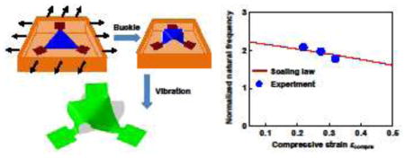
Graphical Abstract
1. Introduction
Structural vibrations have been widely exploited in micro-electromechanical systems (MEMS) for many important applications including oscillators (Antonio et al., 2012; Antonio et al., 2015; Chen et al., 2016a; Chen et al., 2017), actuators (Roche et al., 2014; Polygerinos et al., 2015; Li et al., 2017a; Li et al., 2017b; Niu et al., 2017), mass measurement (Yan et al., 2017a), measurement of mechanical properties (Belmiloud et al., 2008; Etchart et al., 2008; Park et al., 2010; Cakmak et al., 2015; Cermak et al., 2016; Corbin et al., 2016), energy harvesters (Chen et al., 2013; Park et al., 2013; Chen and Jiang, 2015; Chen et al., 2016b; Jiang et al., 2016; Zi et al., 2016; Zou et al., 2016; Fang et al., 2017; Jiang et al., 2017; Zou et al., 2017a; Zou et al., 2017b), micro robots (Diller et al., 2014; Connolly et al., 2015) and acoustics (Nemat-Nasser et al., 2011; Nemat-Nasser and Srivastava, 2011; Bilal et al., 2017a; Bilal et al., 2017b). In most cases, such MEMS rely on two-dimensional (2D) vibrational modes, which are not well suited for multi-directional energy harvesting, anisotropic mechanical property measurement, simultaneous evaluation of multiple mechanical properties (density, modulus, viscosity etc.) and other applications where operation in a 3D space is required.
Recent advances in fabrication/assembly techniques such as those that use controlled mechanical buckling (Khang et al., 2006; Sun et al., 2006; Audoly and Boudaoud, 2008a; Audoly and Boudaoud, 2008b; Audoly and Boudaoud, 2008c; Dias and Audoly, 2014; Xu et al., 2015; Zhang et al., 2015; Chen et al., 2016c; Chen et al., 2016d; Lestringant et al., 2017), self-folding induced by residual stress (Golod et al., 2001; Kong and Wang, 2003; Bell et al., 2007; Huang et al., 2012; Froeter et al., 2013; Huang et al., 2014; Chen et al., 2016e; Bauhofer et al., 2017; Tian et al., 2017), surface instabilities (Yin et al., 2008; Wang and Zhao, 2015; Lin et al., 2016; Wang and Zhao, 2016; Liao et al., 2017; Lin et al., 2017; Ma et al., 2017), capillary forces (Py et al., 2007; Guo et al., 2009; Antkowiak et al., 2011; Hure and Audoly, 2013; Brubaker and Lega, 2016) and temperature changes (Stroganov et al., 2014; Cui et al., 2017) and 3D printing/writing processes (Therriault et al., 2003; Gratson et al., 2004; Lewis et al., 2006; Schaedler et al., 2011; Soukoulis and Wegener, 2011; Fischer and Wegener, 2013; Jang et al., 2013; Farahani et al., 2014; Hong et al., 2015; Farahani et al., 2016; Matlack et al., 2016; Hirt et al., 2017), allow the construction of complex 3D structures and form the structural basis of 3D vibrations. Based on 3D polymers/silicon mesostructures assembled through the techniques of controlled compressive buckling (Xu et al., 2015; Zhang et al., 2015; Liu et al., 2016; Yan et al., 2016a; Yan et al., 2016b; Nan et al., 2017; Shi et al., 2017; Yan et al., 2017b; Zhang et al., 2017), Ning et al., (2017) realized structural vibrations with a broad set of 3D modes. An advantage of 3D vibrations realized by these mechanically assembled structures follows from their vibration behaviour (e.g., natural frequencies) that can be tuned by applying tensile strain to the soft, elastomeric assembly platform. Such tunability is attractive for applications in resonators, energy harvesters and others where continuous adaption of the resonant frequency is needed to follow changes in the operational environment. Therefore, a clear understanding of the strain-dependence of the vibration behaviour is essential for relevant applications. The development of a theoretical model to provide insights into the effect of diverse design parameters is important, in this context.
The existing fundamental studies on the vibrations of buckled structures mainly focus on straight ribbons in the regime of initial postbuckling (Tseng and Dugundji, 1971; Min and Eisley, 1972; Tang and Dowell, 1988; Nayfeh et al., 1995; Kreider and Nayfeh, 1998; Lacarbonara et al., 1998; Lestari and Hanagud, 2001; Emam and Nayfeh, 2004; Noijen et al., 2007; Emam, 2013; Shojaei et al., 2014). For example, Tseng and Dugundji (1971) derived a solution to the linear natural frequency of the first-order vibration mode for a buckled ribbon with fixed ends. This solution shows a proportional dependence on the static deflection amplitude, which, however, does not hold when the static deflection amplitude increases beyond several times of the ribbon thickness (Nayfeh et al., 1995; Kreider and Nayfeh, 1998). Nayfeh et al. (1995) proposed the use of a trial solution to describe the vibration mode, in which the five unknown coefficients were determined by solving an eigenvalue problem numerically. Although this approach can predict the linear natural frequency in both cases of small and large static deflection amplitudes, an explicit solution cannot be obtained due to the complicated form of the vibration mode, limiting its applicability to more complex 3D structures. According to dimensional analysis, Ning et al. (2017) introduced a simple scaling law of the linear natural frequencies for buckled 3D mesostructures with different geometries, but it does not capture the effect of static deflection amplitude, or equivalently, the prestrain used in the assembly. These existing theories cannot be extended directly to buckled ribbons with large deflection amplitudes, due to the strong nonlinear deformations associated with the postbuckling, which also complicates the vibrational analyses.
The present study aims at investigating the linear and nonlinear vibration of complex 3D mesostructures formed via controlled buckling, with a focus on the scenario where the static deflection amplitude is much larger than the structure thickness. An analytical model is developed to explicitly relate the linear natural frequency to the static deflection amplitude or the compressive strain of a buckled ribbon, showing excellent agreements with the results of finite element analyses (FEA). By introducing two fitting parameters to account for the complex geometries and vibrations, this analytical model can be extended to 3D structures with complex topologies. As validated by FEA and experiment measurements, the generalized model predicts reasonably well the relationship between the linear natural frequency and the compressive strain for a broad range of structural vibrations. Furthermore, the analyses of the nonlinear vibration shed light on the influences of vibration amplitude on the natural frequency under free vibrations, as well as effects of load amplitude on the bandwidth under forced vibrations.
2. An analytical model of linear vibration in buckled ribbons
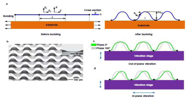
Figure 1 illustrates the geometries of the buckled ribbon and the vibration modes when the structure is subject to the out-of-plane and in-plane vibrations, respectively. The wavy ribbon is formed by compressive buckling of a straight 2D ribbon selectively bonded to a prestrained elastomer at two ends. Release of the prestrain induces compressive forces that are sufficiently large to trigger buckling of the ribbon into an arch shape, as shown in Fig. 1a. Figure 1b shows an experimental image of the mesostructure fabricated by this controlled compressive buckling technique, taken from Sun et al. (2006). Techniques reported recently by Yan et al. (2017c) allow physical transfer of the buckled ribbon onto a vibration stage that can excite both the out-of-plane and in-plane vibrations, as schematically illustrated in Figs. 1c and 1d, respectively. Since the vibration stage is usually much more rigid than the buckled ribbon, the deformations of the stage can be neglected. Consider a slender ribbon whose thickness h is much smaller than the length L, such that it can be modelled as an Euler beam (i.e., with no shear deformation). An analytical model can be then developed to predict the linear vibration of the first-order out-of-plane mode and the first-order in-plane mode at different levels of static deflection amplitude A(0), as elaborated below.
Figure 1.
(a) Schematic of the compressive postbuckling in a straight ribbon induced by the contraction of a pre-strained substrate. (b) an experimental image of the mesostructure formed through the controlled compressive buckling. Reprinted by permission from Macmillan Publishers Ltd: [Nature Nanotechnology] (Sun et al., 2006), copyright (2006). Illustration of (c) the out-of-plane vibration and (d) the in-plane vibration. To illustrate the vibration mode, two phases corresponding to the largest amplitudes during vibration are shown, i.e. green: phase 0°, gray: phase 180°.
2.1. Governing equations
According to the finite-deformation beam theory (Su et al., 2012; Fan et al., 2016; Fan et al., 2017), the deformations of a planar ribbon during compressive postbuckling can be characterized by the displacement of its central axis u = uiEi and the twist angle, where Ei is the unit vector before deformation in the Cartesian coordinates (X, Y, Z). In this section, we focus on the postbuckling of a straight ribbon as shown in Fig. 1a, such that only the displacement components in the X-Z plane are involved.
For a moderate level of compressive strain (e.g., < 30%), an energetic approach (Ko et al., 2009; Wang et al., 2010; Zhu and Chen, 2017) can be exploited to determine the displacements of the ribbon during the postbuckling as
| (1) |
where the compressive strain is the relative dimensional change between the two bonding sites, with l being the distance after compression; εc = π2h2/(3L2) is the critical strain; and is the static deflection amplitude of the buckled ribbon. Here, fixed boundary conditions are assumed at the two ends of the beam, namely
| (2) |
To solve the linear natural frequency and the vibration mode of the buckled ribbon, a harmonic vibration displacement Δui, (Z,t) = ΔAUi(Z) sin(ωt) is superimposed on ui(0)(Z) to give the total displacement as
| (3) |
where Ui (Z) is the vibration mode and ω is the angular frequency. Similar to the works of Tseng and Dugundji (1971) and Tang and Dowell (1988), we expand ΔAUi (Z) in the following series form,
| (4) |
where φ(k) and ϕ(k) are characteristic base functions. Neglecting the displacements of the rigid vibration stage, the fixed boundary condition should be satisfied for the buckled ribbon, i.e.
| (5) |
which require that φ(k)(Z) and ϕ(k)(Z) should satisfy
| (6) |
The harmonic vibration displacement is given by
| (7) |
where Δa(k)(t) = ΔA(k) sin(ωt) can be determined from the Lagrange’s equation of motion. Specifically, the potential energy Ws consists of the membrane energy (W membrane) and the bending energy (W bending) of the ribbon, as given by
| (8) |
where λ is the stretch ratio, κ is the curvature, b is the ribbon width, and E is the elastic modulus of the ribbon material. By neglecting the terms of the 3rd and higher order power of Δa in Eq. (8), the potential energy can be also written as , in which Δa is a n×1 vector {Δa(1), Δa(2),…, Δa(n)}T, and K is an n×n stiffness matrix. Similarly, the kinetic energy can be given as
| (9) |
where Δȧ = {Δȧ(1), Δȧ(2),…, Δȧ(n)}T, is the time derivative of Δa , i.e. Δȧ = d(Δa)/dt , ρ is the density of the ribbon material, and M is an n×n mass matrix. The Lagrange’s equation of motion requires that
| (10) |
which leads to the governing equation
| (11) |
Substitution of Δa=ΔAsin(ωt) into Eq. (11) gives
| (12) |
where ΔA = {ΔA(1), ΔA(2),…, ΔA(n)}T. The linear natural frequency can be then determined by solving the eigenvalue problem, corresponding to the solution of
| (13) |
where |K–ω2M| denotes the determinant of K–ω2M.
2.2. Solution to the linear natural frequency of the first-order out-of-plane mode
To derive a solution to the linear natural frequency and the vibration mode, an analytical form of the vibration displacement ΔAUi (Z) should be constructed using Eq. (4). For the first-order out-of-plane mode, FEA results show that the vibration displacement can be well characterized by the superposition of the following base functions, with two terms (i.e. n=2) in Eq. (4),
| (14) |
| (15) |
The potential energy of the vibration is then derived as
| (16) |
where
| (17) |
The kinetic energy is then written as
| (18) |
where
| (19) |
Substitution of Eqs. (16)–(19) into Eq. (10) gives the governing equations to determine Δa(1) and Δa(2) , i.e.,
| (20) |
| (21) |
Referring to Eq. (11), the stiffness matrix and the mass matrix are given by
| (22) |
According to Eqs. (12) and (13), the linear natural frequency and vibration mode are solved as
| (23) |
| (24) |
where f̂I is the normalized linear natural frequency, whose explicit form is given in Appendix A; the coefficients of Taylor’s expansion, R4(A(0)/L) and R6(A(0)/L), are nonlinear functions of A(0)/L as presented in Appendix B. Noticing that the ribbon thickness is far smaller than its length, i.e. h ≪ L , all the terms except the first one in Eq. (24) can be neglected such that it reduces to
| (25) |
In general, the normalized linear natural frequency f̂1 in Eq. (23) depends on two dimensionless parameters, A(0)/h and A(0)/L, but it can reduce to a single-variable function in certain conditions as we show below.
As shown by Eq. (25), ΔA(1) is much larger than ΔA(2) when the static deflection amplitude of the buckled ribbon is much smaller than the ribbon thickness, i.e. A(0) ≪ h . This means φ(1)(Z) and ϕ(1)(Z) in Eq. (14) and Eq. (15) dominate the vibration mode. In the limit of A(0)/h→0, the normalized linear natural frequency f̂I (Eq. (A1)) approaches
| (26) |
In this condition, the linear natural frequency scales with A(0)/h. When the static deflection amplitude of the buckled ribbon is much larger than the ribbon thickness, i.e. A(0) ≫ h, A(2) is then much larger than A(1), and therefore, ϕ(2)(Z) and ϕ(2)(Z) in Eq. (14) and Eq. (15) dominate the vibration mode. In the limit of A(0)/h→∞ , the normalized linear natural frequency f̂I (Eq. (A1)) approaches
| (27) |
In this condition, the linear natural frequency is independent of A(0)/h. Together with the simplified relationship between the compressive strain (εcompre) and A(0)/L , i.e., , Equation (27) can be re-written as
| (28) |
The above analysis suggests a distinct dependence of the first-order out-of-plane natural frequency at two different limit conditions of A(1) ≫ h . The vibration mode and the linear natural frequency of the buckled ribbon for different levels of static deflection amplitude are summarized in Table 1, including both the precise and simplified forms (for A(1) ≪ h and A(0) ≫ h).
2.3. Solution to the linear natural frequency of the first-order in-plane mode
For the first-order in-plane mode, a set of functions that can both satisfy the boundary conditions and fit well the FEA results are adopted, with simply one term (n=1) in Eq. (4), as given by
| (29) |
| (30) |
The corresponding potential energy of the vibration is
| (31) |
where
| (32) |
and the kinetic energy is
| (33) |
where
| (34) |
The governing equations of the vibration displacements can be then derived as
| (35) |
The linear natural frequency is solved as
| (36) |
where the normalized linear natural frequency f̂II is given by
| (37) |
The corresponding vibration mode is
| (38) |
When the static deflection amplitude of the buckled ribbon is much larger than its thickness, f̂II can also be expressed as a single-variable function of the compressive strain, i.e.
| (39) |
3. Model validation and parametric study of vibration in the buckled ribbon
This section presents validation of the above analytical model by FEA, as well as parametric study of vibration in the buckled ribbon. The FEA were performed using the commercial software ABAQUS. The shape and stress of the buckled ribbon determined from the postbuckling analysis was imported into the modal analysis to calculate the natural frequencies and modes of the linear vibration. Four-node finite-strain shell elements (S4) were used, with at least 20 elements were along the width direction of the ribbon to guarantee the convergence. The material was assumed to be a photopatternable epoxy (SU8), a typical polymer used in 3D assembly. The Young’s modulus, Poisson’s ratio and density of SU8 are E=4.02 GPa, ν=0.22 and ρ=1.2 g/cm3.
3.1. First-order out-of-plane mode for A(0) ≫ h
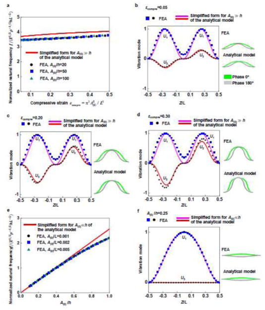
According to the analytical model in Section 2.2, the first-order out-of-plane vibration exhibits different features at different levels of static deflection amplitude (A(0)) of the buckled ribbon, or equivalently, the compressive strain εcompre. We first focus on the case of A(0) ≫ h. The natural frequencies predicted by the simplified form of the analytical model and FEA are compared in Figs. 2a and 2b for the first-order out-of-plane vibration. The FEA results confirmed the independence of the linear natural frequency on A(0)/h, consistent with the analytical model. The analytical results are also in quantitative agreement with FEA results. The analytical and FEA results of vibration mode are presented in Fig. 2b ~ d. In the condition of A(0) ≫ h, the out-of-plane vibration mode predicted by the analytical model agrees well with that of FEA, for the compressive strain varying from 0.05 to 0.30.
Figure 2.
Validation of the analytical model by FEA for the first-order out-of-plane mode: (a) normalized linear natural frequency as a function of the compressive strain when the static deflection amplitude A(0) is much larger than the ribbon thickness h; (b–d) vibration modes for three different compressive strains (0.05, 0.20 and 0.30); (e) normalized linear natural frequency as a function of the A(0)/h when A(0) is smaller than h; (f) vibration mode for A(0)/h=0.25. The solids lines and dots represent the analytical predictions and FEA results, respectively.
3.2. First-order out-of-plane mode for A(0) ≪ h
When the static deflection amplitude (A(0)) of the buckled ribbon is much smaller than the ribbon thickness h, the FEA results in Fig. 2e verified the independence of the linear natural frequency on A(0)/L. When A(0)/h<0.5, the normalized linear natural frequency f̂ based on FEA falls exactly on the straight line predicted by the simplified form of the analytical model for A(0) ≪ h. Beyond A(0)/h=0.9, the FEA results deviate the linear dependence evidently. Fig. 2f shows that the vibration mode based on the analytical prediction also agrees very well with FEA results, with both differing significantly from the condition of A(0) ≫ h.
3.3. Mode change for A(0)/h varying in a wide range
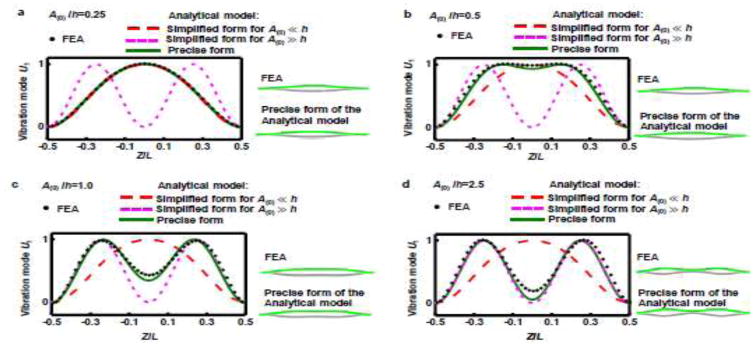
Figure 3a ~ d shows the gradual change of the first-order out-of-plane mode as the static deflection amplitude A(0) increases from a small value relative to the ribbon thickness h. As indicated by Eq. (25), the vibration mode depends on A(0)/h, when A(0) is much smaller than or of the same order as h. In this condition, the in-plane displacement U3 of the vibration mode is typically much smaller than the out-of-plane displacement U1, such that we focus only on U1 in this subsection. As A(0)/h increases from 0.25 to 2.5 in Fig. 3a ~ d,, the precise form of the analytical solution coincides with the results of simplified model for A(0) ≪ h in Fig. 3a (with A(0)/h=0.25), then deviates from it in Figs. 3b and 3c (with A(0)/h=0.5 and A(0)/h=1.0) and finally approaches the results of the simplified model for A(0) ≫ h in Fig. 3d (with A(0)/h=2.5). In all of the above cases, the predictions of precise analytical solution agree with the FEA results.
Figure 3.
Change of the first-order out-of-plane vibration mode for A(0)/h varying in a wide range: (a–d) vibration modes for A(0)/h=0.25, 0.5, 1.0 and 2.5, respectively. Both the results of precise and simplified models are presented for comparison. To illustrate the vibration mode, two phases corresponding to the largest amplitudes during vibration are shown, i.e. green: phase 0°, gray: phase 180°.
3.4. In-plane mode
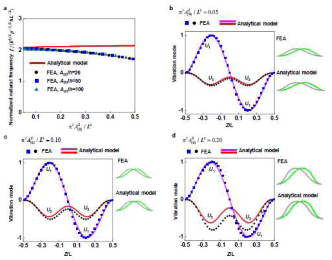
The analytical model in Section 2.3 indicates that the normalized linear natural frequency of the first-order in-plane mode depends on A(0)/L, and is independent of A(0)/h when h is much smaller than L. This is verified by FEA results in Fig. 4a, in which the curves are the same when A(0)/h is fixed to be 20, 50 and 100 respectively. For typical values of , e.g., < 0.2, the analytical predictions of the normalized linear natural frequency and vibration mode agree reasonably well with the FEA results, as shown by Figs. 4 a ~ d.
Figure 4.
Validation of the analytical model by FEA for the first-order in-plane mode: (a) normalized linear natural frequency as a function of ; (b–d) vibration modes for , 0.10 and 0.20, respectively (green: phase 0°, gray: phase 180°).
4. Mechanically-tunable natural frequency in general 3D structures formed through controlled buckling
In this Section, we study the linear natural frequency of vibrations in complex 3D structures formed through controlled buckling of 2D precursors. As the static deflection amplitude of such structures is usually much larger than its thickness, we extend the analytical model developed in Section 2.2 (Eq. (28)) and Section 2.3 (Eq. (39)) to general 3D structures.
4.1. Extension of the analytical model to general 3D structures
The analytical model in Section 2.2 and 2.3 shows that the linear natural frequency f scales with a combination of material/geometry parameters by
| (40) |
This scaling is consistent with the experimental observations in Ning et al. (2017) for general complex 3D structures, where f is also proportional to E1/2ρ−1/2hL−2. Inspired by the structure of the analytical solutions (Eqs. (28) and (39)), f̂ can be expressed by a single-variable function of the compressive strain as
| (41) |
where α, β1 and β2 are three unknown parameters that depend on the layout of the 2D precursor. For β2εcompre comparatively smaller than 1, Eq. (41) can be further simplified as
| (42) |
where β = β1−β2 and α can be determined by fitting the FEA results of the f̂ ~ εcompre curve. As we show in Section 4.2, this scaling law Eq. (42) applies to a plenty number of 3D structural vibrations. In addition, the parameter β measures the sensitivity of the linear natural frequency to the compressive strain.
4.2. Dependence of normalized linear natural frequency on the compressive strain
4.2.1. 3D helical structures on a rigid substrate
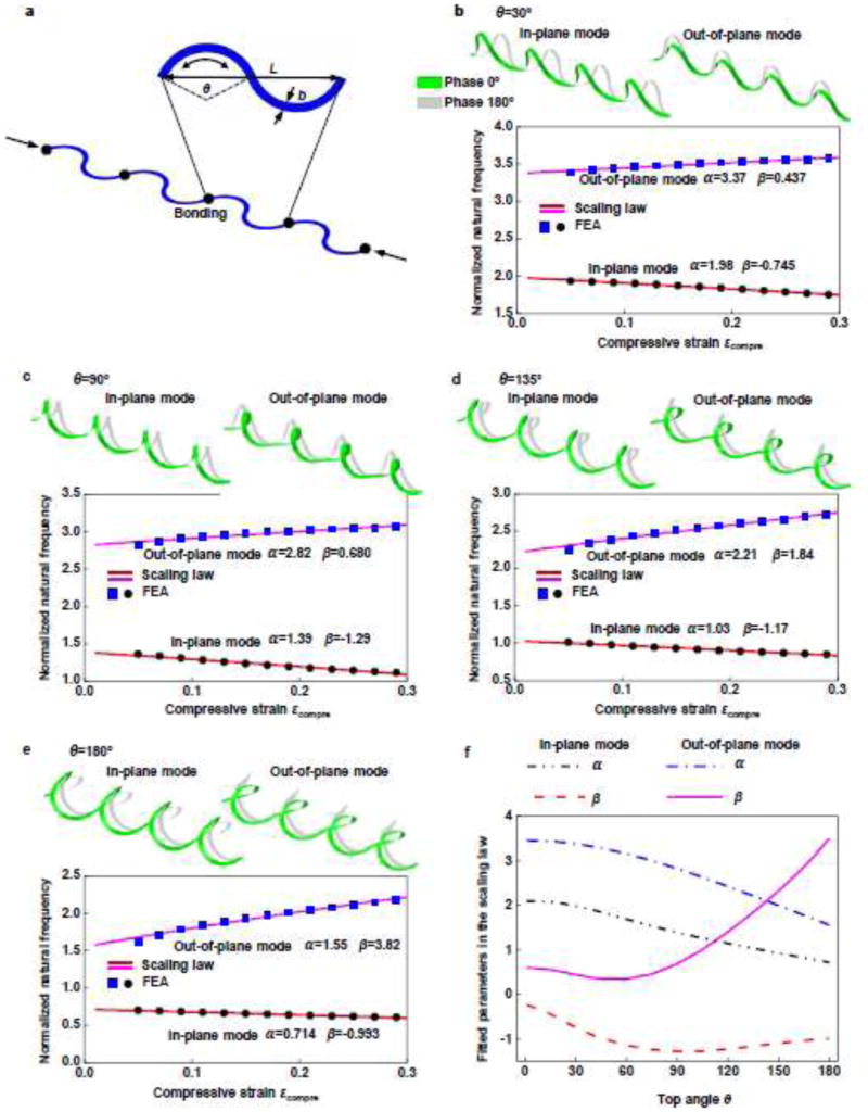
3D helical structures are attractive for their potentials in replacing 2D structures in a broad range of microsystems (Farahani et al., 2014). This type of structures can be formed from the controlled buckling of 2D serpentine ribbons (Liu et al., 2016). The top angle of the 2D serpentine ribbons (θ in Fig. 5a) and the compressive strain play a crucial role in determining the 3D shape after buckling, as well as the linear natural frequency. Figure 5b ~ e presents the FEA results of the normalized linear natural frequency f̂ of the first-order in-plane mode and the first-order out-of-plane mode for the top angle θ ranging from 0° to 180° and the compressive strain εcompre from 0.05 to 0.3. The scaling law in Eq. (42) agrees remarkably well with FEA for all of the different parameter combinations, as shown in Fig. 5b ~ e. Figure 5f gives the two parameters α and β determined from the FEA results (i.e., the f̂ ~ εcompre curve), for different top angles. These results suggest that the normalized linear natural frequency decreases as θ increases. The sensitivity of the normalized linear natural frequency to the compressive strain strongly depends on the top angle θ, as evidenced by the β ~ θ curves in Fig. 5f.
Figure 5.
Extension of the analytical model to 3D helical structures, with validations by FEA: (a) illustration of the 2D precursors and geometric parameters; (b–e) Illustration of the first-order in-plane mode and the first-order out-of-plane mode (green: phase 0°, gray: phase 180°), and the corresponding normalized linear natural frequencies as a function of the compressive strain, for different top angles (30°, 90°, 135° and 180°) of the 2D structure; the solid lines and the dots represent the results based on the scaling law and the FEA, respectively; (f) Parameters α and β that characterize the scaling law of linear natural frequency, as a function of the top angle.
4.2.2. Other representative 3D structures on a rigid substrate
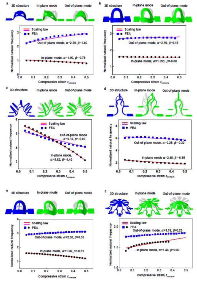
Figure 6 demonstrates the results of vibration in some other representative 3D structures, including those with membrane shapes (Fig. 6a and Fig. 6b), ribbon shapes (Fig. 6c and Fig. 6d), and a hybrid of them (Fig. 6e and Fig. 6f). For each of the example, the first-order in-plane mode and the first-order out-of-plane mode are studied. The linear natural frequency according to the scaling law with two fitting parameters agrees very well with the FEA. These results suggest the applicability of the scaling law Eq. (42) to a broad set of vibrations in 3D structures formed by the controlled buckling.
Figure 6.
Extension of the analytical model to other representative 3D structures, with validations by FEA: (a) and (b) membrane-shaped structures; (c) and (d) ribbon-shaped structures; (e) and (f) structures with a hybrid of membrane and ribbon shapes; the solid lines and the dots represent the results based on the scaling law and the FEA, respectively
4.2.3. Buckled ribbon structure on a soft substrate
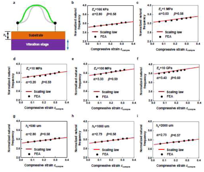
In the above study, we investigated the vibration of 3D structures transferred onto a rigid substrate. In other application circumstances, e.g., for integration with biological tissues, the 3D structures simply reside on the original elastomer substrate. Here, the deformation of the substrate may have some influence on the structural vibration, depending on the substrate modulus (Es) and thickness (hs). Although the scaling law Eq. (42) is developed without consideration of the substrate deformation, FEA and experimental results on wide-ranging parameters and geometries, to be shown in Figs. 7 and 8, illustrate the utility of this scaling law in the structural vibration on a soft substrate. The FEA performed in Section 4.2.3 and Section 4.2.4 assumed a perfect bonding between the bonding site and the substrate.
Figure 7.
Extension of the analytical model to a buckled ribbon on a soft substrate, with validations by FEA, highlighting the effects of the substrate modulus and substrate thickness on the linear natural frequency: (a) Schematic illustration of the model; (b–f) normalized linear natural frequency as a function of the compressive strain for a fixed substrate thickness (500 um) and a wide range of substrate modulus (166 kPa, 1 MPa, 10 Mpa, 100 MPa and 10 GPa); (g–i) normalized linear natural frequency as a function of the compressive strain for a fixed substrate modulus (166 kPa) and three different substrate thicknesses (500 um, 1000 um and 2000 um). The solid lines and the dots represent the results based on the scaling law and the FEA, respectively.
Figure 8.
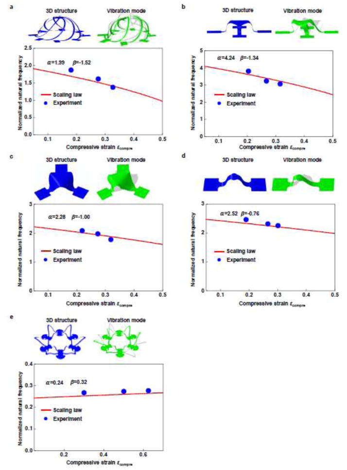
Experimental validation of the scaling law for five representative 3D structures: (a) cage; (b) table; (c) triangular membrane; (d) ribbon and (e) flower, in an order of decreasing sensitivity (β) of the linear natural frequency to the compressive strain. The solid lines and the dots represent the results based on the scaling law and the experiment, respectively.
We consider a buckled ribbon on the substrate whose modulus ranges from 166 kPa to 10 GPa, thickness ranges from 500 um to 2000 um and compressive strain ranges from 0.05 to 0.35. The natural frequency of first-order out-of-plane mode based on the scaling law matches well with the FEA results (Fig. 7), for all of the different cases. For the same compressive strain εcompre and substrate thickness, the linear natural frequency increases as the substrate modulus, as shown by Fig. 7b ~ f. When the substrate modulus is 10 GPa, the fitted parameters in the scaling law Eq. (42) are α =3.43 and β =0.60 respectively, very close to the values (α =3.47 and β =0.61) for ideal rigid substrate. In the controlled buckling process, the substrate usually has a small modulus, e.g. dragon skin (166 kPa) and PDMS (~ 2 MPa). As the substrate modulus reduces from 10 GPa to 166 kPa, the fitted parameter α decreases by about 20% (from 3.43 to 2.80), while β remains almost the same. The above results indicate that the substrate modulus has a negligible influence on the sensitivity of the linear natural frequency to the compressive strain.
Figure 7g ~ i presents a range of f̂ ~ εcompre curves for different substrate thickness (from 500 um to 2000 um) and fixed substrate modulus (166 kPa), indicating very minor effect of substrate thickness on the linear natural frequency in the range of interest.
4.2.4. General 3D structures on a soft substrate
Figure 8 illustrates the utility of the scaling law to general 3D structures on a soft substrate, with experimental validations. Five representative 3D structures, including the cage, table, triangle membrane, arch with a disk and two-layer flower, were taken into account, with all residing on a soft substrate (Dragon skin, modulus 166 kPa). In the experiments, each of the 3D structures is formed via controlling buckling under three different strains (Xu et al., 2015; Zhang et al., 2015), and then activated to induce natural vibration. The vibrational behavior was investigated by an automatic apparatus that consisted of a laser sensing component and an actuation component. The structures were attached on a 3D-printed stage with high-performance commercial piezoelectric actuators, which excited the vibrations of the structures. A laser beam was focused on the structure and the scattered beam was collected and redirected to a photodetector (Thorlabs, DET 110). The vibrating structure resulted in the fluctuation in the intensity of the scattered laser collected by the photodetector. A high-precision lock-in amplifier was used to measure the amplitude of the fluctuating photocurrent. The maximum amplitude of photocurrent measured in this way corresponded to the resonance of the structures. The vibration was automatically controlled by a signal generator. A Labview program was developed to sweep the desired range of frequency, record data from the lock-in amplifier, and control the signal generator. This apparatus enabled an accurate and automatic way to study the vibration behavior of the microscale 3D structures.
The natural frequency obtained from experiment matches well with the prediction of the scaling law, for all of the different examples. Note that the two parameters α and β associated with the scaling law were determined from FEA, without referring to the experiment results. In general, the scaling law slightly overestimates the natural frequency compared to the experimental results, especially at relative high compressive strains. This trend can be explained by the simplified boundary conditions in the modeling. In specific, the FEA assume a perfect bonding of 3D structures with the substrate without any delamination, but in experiments, a slight level of partial delamination might occur due to the finite interfacial strength, especially at relative large compression. Therefore, the boundary condition assumed in the model is a bit more rigid than that in experiments, resulting in a slightly overestimated natural frequency.
The 3D geometry plays an important role on the sensitivity of the linear natural frequency to the compressive strain. For example, the linear natural frequency of cage (Fig. 8a) depends highly on the compressive strain (β = 1.52), while that of the flower (Fig. 8e) is almost independent on the compressive strain (β = 0.32).
Due to the assumption that the
5. Nonlinear vibration
In the above analysis, we assume that the vibration amplitude is much smaller than the structure thickness such that the vibration is linear. In this section, we study the nonlinear vibration of the buckled ribbon and complex 3D structures formed through controlled buckling, focusing on two important quantities (natural frequency and bandwidth).
5.1. Nonlinear natural frequency
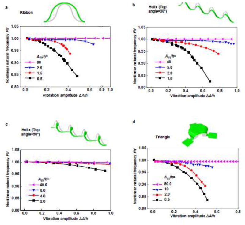
To calculate the nonlinear natural frequency by FEA, a time-harmonic displacement is applied to the bonding site to activate the vibration, and then removed after several cycles to allow free vibration of the structure. After a sufficiently long time of free vibration (>500 periods), the displacement as a function of time is sampled and the Fourier transformation then gives the amplitude-frequency spectrum, from which the natural frequency can be obtained. As shown by Fig. 9a, for the first-order out-of-plane mode of a buckled ribbon whose static deflection amplitude is on the same order of amplitude as the ribbon thickness, the nonlinear natural frequency is smaller than the linear natural frequency and decreases as the vibration amplitude increases (see the black, red and blue curves for the case A(0) = 0.5h, 1.5h and 2.5h respectively). This trend is consistent with the predictions by the subspace projection method reported in literature (Tseng and Dugundji, 1971). However for a buckled ribbon whose static deflection amplitude is much larger than the ribbon thickness (e.g., by ≥ 40 times), the nonlinear natural frequency is almost the same as the linear natural frequency, even when the vibration amplitude is 1.4 times of the ribbon thickness, indicating a very weak nonlinear effect.
Figure 9.
Nonlinear natural frequency of four mechanically-assembled structures as a function of vibration amplitude (ΔA/h) for four different static deflection amplitudes (A(0)/h): (a) buckled ribbon; (b) and (c) helical structures with top angles of 30° and 90°; and (d) triangular membrane.
The above results can be understood based on the dimensional analysis of the potential energy of vibration. For the first-order out-of-plane mode of a buckled ribbon, the potential energy consists of the membrane energy (Wm) and the bending energy (Wb) as discussed in Section 2.1. In linear vibration, the potential energy (Ws) is proportional to the square of the vibration amplitude (Δa), i.e.
| (43) |
When the vibration amplitude Δa increases to the same order of amplitude as the ribbon thickness h, the membrane energy may contribute a nonlinear term to the potential energy, i.e. . For a ribbon in the regime of initial postbuckling, a large membrane energy may arise during vibration as the overall length of the ribbon inevitably changes. Therefore, when the vibration amplitude Δa increases to the same order as h, the nonlinear term Wm(Nonlinear) can be significant. However, for a buckled ribbon with large static deflection amplitude, the membrane energy becomes negligible because a curved ribbon can easily deform to accommodate the vibrational deformations without changing its length. This mechanism prohibits the nonlinear term Wm(Nonlinear). Meanwhile, for the bending energy to contribute a nonlinear term to the potential energy, the vibration amplitude needs to on the same order as the ribbon length, noticing that Wb ∝ h3. The above qualitative analysis is consistent with the reports in literature that a straight ribbon with two fixed-ends can exhibit strong nonlinear vibration (Tseng and Dugundji 1970; Yamaki and Mori 1980; Yamaki et al., 1980).
A similar trend is also observed in 3D helical (with two different top angles, 30° and 90°, in the 2D precursors) and triangular membrane structures, as shown by Fig. 9b ~ d for the out-of-plane vibration mode. In these general 3D vibrations, the nonlinear effect also becomes weaker as the static deflection amplitude increases, and is negligible for A(0)/h≥40.
5.2. Bandwidth
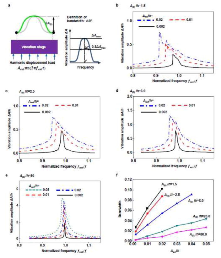
Bandwidth is an important characteristic of the nonlinear vibration. As shown in Fig 10a, the bandwidth is defined according to the vibration amplitude-frequency spectrum in forced vibration. For the linear vibration with infinitesimal amplitude, a sharp peak occurs at the natural frequency, yielding a zero bandwidth if the dissipations are ignored. When the nonlinear effect is taken into account, the bandwidth becomes non-zero and increases with increasing the vibration amplitude. As discussed in Section 5.1., the nonlinearity of vibration becomes weak for buckled ribbons with the static deflection amplitude much larger than its thickness. As such, we can anticipate that the resulting vibration has a small bandwidth compared to the case of small static deflection amplitude. This conclusion is supported by FEA, as shown in Fig. 10b ~ f. In the cases of A(0) = 1.5h and 2.5h, the amplitude-frequency spectrum has a broad band around the peak when the vibration amplitude equals to the ribbon thickness, while in the case of A(0) = 80h, the peak is still quite sharp even if the vibration amplitude is five times of the ribbon thickness. Figure 10f shows the bandwidth quantitatively as a function of the amplitude of the external loading for a buckled ribbon with wide-ranging static deflection amplitudes. In all of the different cases, the bandwidth can always be enhanced by more than 4 times through increasing the amplitude of the external loading.
Figure 10.
Bandwidth of the amplitude-frequency spectrum under forced nonlinear vibration of a buckled ribbon for a wide range of static deflection amplitude (A(0)/h) and amplitude (Aext/h) of external loading: (a) schematic illustration of the FEA model and the definition of the bandwidth; (b–e) frequency spectrum of the vibration amplitude for A(0)/h = 2.5, 2.5, 6.0 and 80, respectively; (f) bandwidth as a function of Aext/h for five different A(0)/h (1.5, 2.5, 6.0, 20 and 80).
6. Conclusions and discussions
This paper presents a systematic study of the linear and nonlinear vibrations of mechanically assembled 3D structures through analytical modeling, FEA and experiment. An explicit analytical solution is derived for the vibration mode and the linear natural frequency of a buckled ribbon. Both the analytical solution and FEA reveal a change of vibration mode as the static deflection amplitude of the buckled ribbon increases from a very small value compared to the ribbon thickness. The vibration mode of the buckled ribbon at large static deflection amplitude is found to be distinct from that of a straight ribbon (Tseng and Dugundji, 1970). In the condition of relative large static deflection amplitudes, the solution of the linear natural frequency can be well extended to general, complex 3D structures, either on rigid or soft substrates, as validated by both FEA and experiments. The developed scaling law Eq. (42) can serve as a tool for the experimentalists to measure the sensitivity of the linear natural frequency to the compressive strain, noting that the measurement of linear natural frequencies at two different compressive strains provides enough data to determine the parameter β. In the meanwhile, the parameter β can also be determined from FEA with sufficient accuracy without referring to the experiment results, as suggested by the five cases shown in Figure 8. For some of 3D structures studied herein, the linear natural frequency is very sensitive to the compressive strain, as evidenced by the large magnitude of parameter β in the developed scaling law. The change of the linear natural frequency (f) indicates the change of the equivalent stiffness (K) or the equivalent mass (M) of the structural vibration, as . Therefore, these 3D structures can be potentially utilized as tunable resonators to measure, simultaneously, the stiffness and mass of other coupling media. In the regime of nonlinear vibration, FEA calculations suggest that the increase of amplitude of external loading represents an effective means to enhance the bandwidth. The results also indicate a reduced nonlinearity of vibration as the static deflection amplitude of the 3D structures increases. This study can serve as design guidelines for the development of new 3D vibrational micro-platforms or efficient energy harvesters.
Highlights.
Analytic solution of vibration modes & linear natural frequency of a buckled ribbon
Mode change as the static deflection amplitude of buckled ribbon increases
Scaling law of linear natural frequency for general, complex 3D structures
Reduced vibration nonlinearity as deflection amplitudes of 3D structures increase
Acknowledgments
Y.Z. acknowledges support from the National Natural Science Foundation of China (# 11722217), the Thousand Young Talents Program of China and the Tsinghua National Laboratory for Information Science and Technology. Y.X. acknowledges the support from the Ryan Fellowship and the Northwestern University International Institute for Nanotechnology. Y.H. acknowledges the support from NSF (# CMMI1400169, # CMMI1534120 and # CMMI1635443) and NIH (# R01EB019337).
Appendix A. Explicit form of f̂ I in Eq. (23)
The explicit form of the normalized linear natural frequency in Eq. (23) is
| (A44) |
Appendix B. Expressions of the functions R4 and R6 in Eq. (24)
The vibration mode in Eq. (24) can be derived as
| (B1) |
where is a nonlinear function. The Taylor’s expansion of R leads to Eq. (24), where
| (B2) |
and
| (B3) |
Appendix C. Expression of coefficient in Table 1
Table 1.
The analytical model for the first-order out-of-plane vibration of the buckled ribbon
| Vibration mode | Normalized linear natural frequency |
|||
|---|---|---|---|---|
| Simplified form for A(0) ≪ h |
|
|
||
| Simplified form for A(0) ≫ h |
|
|
||
| Precise form |
|
|
Here, C(ΔA(2)/ΔA(1)) is a single-variable function to normalize the mode, as presented in Appendix C.
The function in Table 1 is
| (C1) |
Footnotes
Publisher's Disclaimer: This is a PDF file of an unedited manuscript that has been accepted for publication. As a service to our customers we are providing this early version of the manuscript. The manuscript will undergo copyediting, typesetting, and review of the resulting proof before it is published in its final citable form. Please note that during the production process errors may be discovered which could affect the content, and all legal disclaimers that apply to the journal pertain.
References
- Antkowiak A, Audoly B, Josserand C, Neukirch S, Rivetti M. Instant fabrication and selection of folded structures using drop impact. Proc Natl Acad Sci USA. 2011;108:10400–10404. doi: 10.1073/pnas.1101738108. [DOI] [PMC free article] [PubMed] [Google Scholar]
- Antonio D, Zanette DH, Lopez D. Frequency stabilization in nonlinear micromechanical oscillators. Nat Commun. 2012;3:806. doi: 10.1038/ncomms1813. [DOI] [PubMed] [Google Scholar]
- Antonio D, Czaplewski DA, Guest JR, Lopez D, Arroyo SI, Zanette DH. Nonlinearity-Induced Synchronization Enhancement in Micromechanical Oscillators. Phys Rev Lett. 2015;114:034103. doi: 10.1103/PhysRevLett.114.034103. [DOI] [PubMed] [Google Scholar]
- Audoly B, Boudaoud A. Buckling of a stiff film bound to a compliant substrate - Part I: Formulation, linear stability of cylindrical patterns, secondary bifurcations. J Mech Phys Solids. 2008a;56:2401–2421. [Google Scholar]
- Audoly B, Boudaoud A. Buckling of a stiff film bound to a compliant substrate – Part II: A global scenario for the formation of herringbone pattern. J Mech Phys Solids. 2008b;56:2422–2443. [Google Scholar]
- Audoly B, Boudaoud A. Buckling of a stiff film bound to a compliant substrate – Part III: Herringbone solutions at large buckling parameter. J Mech Phys Solids. 2008c;56:2444–2458. [Google Scholar]
- Bauhofer AA, Krödel S, Rys J, Bilal OR, Constantinescu A, Daraio C. Harnessing photochemical shrinkage in direct laser writing for shape morphing of polymer sheets. Adv Mater. 2017 doi: 10.1002/adma.201703024. published on line. http://dx.doi.org/10.1002/adma.201703024. [DOI] [PubMed]
- Bell DJ, Bauert TE, Zhang L, Dong LX, Sun Y, Grutzmacher D, Nelson BJ. Directed batch assembly of three-dimensional helical nanobelts through angular winding and electroplating. Nanotechnology. 2007;18:055304. [Google Scholar]
- Belmiloud N, Dufour I, Colin A, Nicu L. Rheological behavior probed by vibrating microcantilevers. Appl Phys Lett. 2008;92:041907. [Google Scholar]
- Bilal OR, Foehr A, Daraio C. Bistable metamaterial for switching and cascading elastic vibrations. Proc Natl Acad Sci USA. 2017a;114:4603–4606. doi: 10.1073/pnas.1618314114. [DOI] [PMC free article] [PubMed] [Google Scholar]
- Bilal OR, Foehr A, Daraio C. Reprogrammable phononic metasurfaces. Adv Mater. 2017b;29:1700628. doi: 10.1002/adma.201700628. [DOI] [PubMed] [Google Scholar]
- Brubaker ND, Lega J. Capillary-induced deformations of a thin elastic sheet. Philos Trans R Soc A-Math Phys Eng Sci. 2016;374:20150169. doi: 10.1098/rsta.2015.0169. [DOI] [PMC free article] [PubMed] [Google Scholar]
- Cakmak O, Ermek E, Kilinc N, Yaralioglu GG, Urey H. Precision density and viscosity measurement using two cantilevers with different widths. Sens Actuator A-Phys. 2015;232:141–147. [Google Scholar]
- Cermak N, Olcum S, Delgado FF, Wasserman SC, Payer KR, Murakami MA, Knudsen SM, Kimmerling RJ, Stevens MM, Kikuchi Y, Sandikci A, Ogawa M, Agache V, Baleras F, Weinstock DM, Manalis SR. High-throughput measurement of single-cell growth rates using serial microfluidic mass sensor arrays. Nat Biotechnol. 2016;34:1052–1059. doi: 10.1038/nbt.3666. [DOI] [PMC free article] [PubMed] [Google Scholar]
- Chen C, Zanette DH, Czaplewski DA, Shaw S, Lopez D. Direct observation of coherent energy transfer in nonlinear micromechanical oscillators. Nat Commun. 2017;8:15523. doi: 10.1038/ncomms15523. [DOI] [PMC free article] [PubMed] [Google Scholar]
- Chen CY, Zanette DH, Guest JR, Czaplewski DA, Lopez D. Self-Sustained Micromechanical Oscillator with Linear Feedback. Phys Rev Lett. 2016a;117:017203. doi: 10.1103/PhysRevLett.117.017203. [DOI] [PubMed] [Google Scholar]
- Chen J, Zhu G, Yang WQ, Jing QS, Bai P, Yang Y, Hou TC, Wang ZL. Harmonic-Resonator-Based Triboelectric Nanogenerator as a Sustainable Power Source and a Self-Powered Active Vibration Sensor. Adv Mater. 2013;25:6094–6099. doi: 10.1002/adma.201302397. [DOI] [PubMed] [Google Scholar]
- Chen LQ, Jiang WA, Panyam M, Daqaq MF. A broadband internally resonant vibratory energy harvester. J Vib Acoust-Trans ASME. 2016b;138:061007. [Google Scholar]
- Chen LQ, Jiang WA. Internal resonance energy harvesting. J Appl Mech-Trans ASME. 2015;82:031004. [Google Scholar]
- Chen YL, Liu YL, Yan Y, Zhu Y, Chen X. Helical coil buckling mechanism for a stiff nanowire on an elastomeric substrate. J Mech Phys Solids. 2016c;95:25–43. [Google Scholar]
- Chen YL, Zhu Y, Chen X, Liu YL. Mechanism of the transition from in-Plane buckling to helical buckling for a stiff nanowire on an elastomeric substrate. J Appl Mech-Trans ASME. 2016d;83:041011. [Google Scholar]
- Chen Z, Huang GS, Trase I, Han XM, Mei YF. Mechanical self-assembly of a strain-engineered flexible layer: wrinkling, rolling, and twisting. Phys Rev Appl. 2016e;5:017001. [Google Scholar]
- Connolly F, Polygerinos P, Walsh CJ, Bertoldi K. Mechanical programming of soft actuators by varying fiber angle. Soft Robot. 2015;2:26–32. [Google Scholar]
- Corbin EA, Adeniba OO, Ewoldt RH, Bashir R. Dynamic mechanical measurement of the viscoelasticity of single adherent cells. Appl Phys Lett. 2016;108:093701. [Google Scholar]
- Cui J, Yao S, Huang Q, Adams JGM, Zhu Y. Controlling the self-folding of a polymer sheet using a local heater: the effect of the polymer-heater interface. Soft Matter. 2017;13:3863–3870. doi: 10.1039/c7sm00568g. [DOI] [PubMed] [Google Scholar]
- Dias MA, Audoly B. A non-linear rod model for folded elastic strips. J Mech Phys Solids. 2014;62:57–80. [Google Scholar]
- Diller E, Zhuang J, Lum GZ, Edwards MR, Sitti M. Continuously distributed magnetization profile for millimeter-scale elastomeric undulatory swimming. Appl Phys Lett. 2014;104:174101. [Google Scholar]
- Emam SA, Nayfeh AH. On the nonlinear dynamics of a buckled beam subjected to a primary-resonance excitation. Nonlinear Dyn. 2004;35:1–17. [Google Scholar]
- Emam SA. Approximate analytical solutions for the nonlinear free vibrations of composite beams in buckling. Compos Struct. 2013;100:186–194. [Google Scholar]
- Etchart I, Chen H, Dryden P, Jundt J, Harrison C, Hsu K, Marty F, Mercier B. MEMS sensors for density-viscosity sensing in a low-flow microfluidic environment. Sens Actuator A-Phys. 2008;141:266–275. [Google Scholar]
- Fan ZC, Zhang YH, Ma Q, Zhang F, Fu HR, Hwang KC, Huang YG. A finite deformation model of planar serpentine interconnects for stretchable electronics. Int J Solids Struct. 2016;91:46–54. doi: 10.1016/j.ijsolstr.2016.04.030. [DOI] [PMC free article] [PubMed] [Google Scholar]
- Fan ZC, Wu J, Ma Q, Liu Y, Su YW, Hwang KC. Post-buckling analysis of curved beams. J Appl Mech-Trans ASME. 2017;84:031007. [Google Scholar]
- Fang ZW, Zhang YW, Li X, Ding H, Chen LQ. Integration of a nonlinear energy sink and a giant magnetostrictive energy harvester. J Sound Vib. 2017;391:35–49. [Google Scholar]
- Farahani RD, Chizari K, Therriault D. Three-dimensional printing of freeform helical microstructures: a review. Nanoscale. 2014;6:10470–10485. doi: 10.1039/c4nr02041c. [DOI] [PubMed] [Google Scholar]
- Farahani RD, Dube M, Therriault D. Three-Dimensional Printing of Multifunctional Nanocomposites: Manufacturing Techniques and Applications. Adv Mater. 2016;28:5794–5821. doi: 10.1002/adma.201506215. [DOI] [PubMed] [Google Scholar]
- Fischer J, Wegener M. Three-dimensional optical laser lithography beyond the diffraction limit. Laser Photonics Rev. 2013;7:22–44. [Google Scholar]
- Froeter P, Yu X, Huang W, Du F, Li MY, Chun I, Kim SH, Hsia KJ, Rogers JA, Li XL. 3D hierarchical architectures based on self-rolled-up silicon nitride membranes. Nanotechnology. 2013;24:475301. doi: 10.1088/0957-4484/24/47/475301. [DOI] [PubMed] [Google Scholar]
- Golod SV, Prinz VY, Mashanov VI, Gutakovsky AK. Fabrication of conducting GeSi/Si micro- and nanotubes and helical microcoils. Semicond Sci Technol. 2001;16:181–185. [Google Scholar]
- Gratson GM, Xu MJ, Lewis JA. Microperiodic structures - direct writing of three-dimensional webs. Nature. 2004;428:386–386. doi: 10.1038/428386a. [DOI] [PubMed] [Google Scholar]
- Guo XY, Li H, Ahn BY, Duoss EB, Hsia KJ, Lewis JA, Nuzzo RG. Two- and three-dimensional folding of thin film single-crystalline silicon for photovoltaic power applications. Proc Natl Acad Sci USA. 2009;106:20149–20154. doi: 10.1073/pnas.0907390106. [DOI] [PMC free article] [PubMed] [Google Scholar]
- Hirt L, Reiser A, Spolenak R, Zambelli T. Additive Manufacturing of Metal Structures at the Micrometer Scale. Adv Mater. 2017;29:1604211. doi: 10.1002/adma.201604211. [DOI] [PubMed] [Google Scholar]
- Hong SM, Sycks D, Chan HF, Lin ST, Lopez GP, Guilak F, Leong KW, Zhao XH. 3D printing of highly stretchable and tough hydrogels into complex, cellularized structures. Adv Mater. 2015;27:4035–4040. doi: 10.1002/adma.201501099. [DOI] [PMC free article] [PubMed] [Google Scholar]
- Huang W, Yu X, Froeter P, Xu RM, Ferreira P, Li XL. On-chip inductors with self-rolled-up sinx nanomembrane tubes: a novel design platform for extreme miniaturization. Nano Lett. 2012;12:6283–6288. doi: 10.1021/nl303395d. [DOI] [PubMed] [Google Scholar]
- Huang W, Koric S, Yu X, Hsia KJ, Li XL. Precision structural engineering of self-rolled-up 3D nanomembranes guided by transient quasi-static fem modeling. Nano Lett. 2014;14:6293–6297. doi: 10.1021/nl5026369. [DOI] [PubMed] [Google Scholar]
- Hure J, Audoly B. Capillary buckling of a thin film adhering to a sphere. J Mech Phys Solids. 2013;61:450–471. [Google Scholar]
- Ilic B, Krylov S, Craighead HG. Young’s modulus and density measurements of thin atomic layer deposited films using resonant nanomechanics. J Appl Phys. 2010;108:044317. [Google Scholar]
- Jang DC, Meza LR, Greer F, Greer JR. Fabrication and deformation of three-dimensional hollow ceramic nanostructures. Nat Mater. 2013;12:893–898. doi: 10.1038/nmat3738. [DOI] [PubMed] [Google Scholar]
- Jiang WA, Chen LQ, Ding H. Internal resonance in axially loaded beam energy harvesters with an oscillator to enhance the bandwidth. Nonlinear Dyn. 2016;85:2507–2520. [Google Scholar]
- Jiang XY, Zou HX, Zhang WM. Design and analysis of a multi-step piezoelectric energy harvester using buckled beam driven by magnetic excitation. Energy Convers Manag. 2017;145:129–137. [Google Scholar]
- Khang DY, Jiang HQ, Huang YG, Rogers JA. A stretchable form of single-crystal silicon for high-performance electronics on rubber substrates. Science. 2006;311:208–212. doi: 10.1126/science.1121401. [DOI] [PubMed] [Google Scholar]
- Ko HC, Shin G, Wang SD, Stoykovich MP, Lee JW, Kim DH, Ha JS, Huang YG, Hwang KC, Rogers JA. Curvilinear electronics formed using silicon membrane circuits and elastomeric transfer elements. Small. 2009;5:2703–2709. doi: 10.1002/smll.200900934. [DOI] [PubMed] [Google Scholar]
- Kong XY, Wang ZL. Spontaneous polarization-induced nanohelixes, nanosprings, and nanorings of piezoelectric nanobelts. Nano Lett. 2003;3:1625–1631. [Google Scholar]
- Kreider W, Nayfeh AH. Experimental investigation of single-mode responses in a fixed-fixed buckled beam. Nonlinear Dyn. 1998;15:155–177. [Google Scholar]
- Lacarbonara W, Nayfeh AH, Kreider W. Experimental validation of reduction methods for nonlinear vibrations of distributed-parameter systems: Analysis of a buckled beam. Nonlinear Dyn. 1998;17:95–117. [Google Scholar]
- Lestari W, Hanagud S. Nonlinear vibration of buckled beams: some exact solutions. Int J Solids Struct. 2001;38:4741–4757. [Google Scholar]
- Lestringant C, Maurini C, Lazarus A, Audoly B. Buckling of an elastic ridge: competition between wrinkles and creases. Phys Rev Lett. 2017;118:165501. doi: 10.1103/PhysRevLett.118.165501. [DOI] [PubMed] [Google Scholar]
- Lewis JA, Smay JE, Stuecker J, Cesarano J. Direct ink writing of three-dimensional ceramic structures. J Am Ceram Soc. 2006;89:3599–3609. [Google Scholar]
- Li WB, Zhang WM, Zou HX, Peng ZK, Meng G. A novel variable stiffness mechanism for dielectric elastomer actuators. Smart Mater Struct. 2017a;26:085033. [Google Scholar]
- Li XQ, Li WB, Zhang WM, Zou HX, Peng ZK, Meng G. Magnetic force induced tristability for dielectric elastomer actuators. Smart Mater Struct. 2017b;26:105007. [Google Scholar]
- Liao X, Xiao J, Ni Y, Li C, Chen X. Self-assembly of islands on spherical substrates by surface instability. ACS Nano. 2017;11:2611–2617. doi: 10.1021/acsnano.6b07108. [DOI] [PubMed] [Google Scholar]
- Lin S, Mao Y, Radovitzky R, Zhao X. Instabilities in confined elastic layers under tension: fringe, fingering and cavitation. J Mech Phys Solids. 2017;106:229–256. [Google Scholar]
- Lin ST, Cohen T, Zhang T, Yuk H, Abeyaratnea R, Zhao XH. Fringe instability in constrained soft elastic layers. Soft Matter. 2016;12:8899–8906. doi: 10.1039/c6sm01672c. [DOI] [PMC free article] [PubMed] [Google Scholar]
- Liu Y, Yan Z, Lin Q, Guo XL, Han MD, Nan K, Hwang KC, Huang YG, Zhang YH, Rogers JA. Guided formation of 3d helical mesostructures by mechanical buckling: analytical modeling and experimental validation. Adv Funct Mater. 2016;26:2909–2918. doi: 10.1002/adfm.201505132. [DOI] [PMC free article] [PubMed] [Google Scholar]
- Ma L, Peng J, Wu C, He L, Ni Y. Sphere-to-tube transition toward nanotube formation: a universal route by inverse plateau–rayleigh instability. ACS Nano. 2017;11:2928–2933. doi: 10.1021/acsnano.6b08248. [DOI] [PubMed] [Google Scholar]
- Matlack KH, Bauhofer A, Krödel S, Palermo A, Daraio C. Composite 3D-printed metastructures for low-frequency and broadband vibration absorption. Proc Natl Acad Sci USA. 2016;113:8386–8390. doi: 10.1073/pnas.1600171113. [DOI] [PMC free article] [PubMed] [Google Scholar]
- Min GB, Eisley JG. Nonlinear vibration of buckled beams. J Eng Ind. 1972;94:637–645. [Google Scholar]
- Nan KW, Luan HW, Yan Z, Ning X, Wang YQ, Wang A, Wang JT, Han MD, Chang M, Li K, Zhang YT, Huang W, Xue YG, Huang YG, Zhang YH, Rogers JA. Engineered elastomer substrates for guided assembly of complex 3D mesostructures by spatially nonuniform compressive buckling. Adv Funct Mater. 2017;27:1604281. doi: 10.1002/adfm.201604281. [DOI] [PMC free article] [PubMed] [Google Scholar]
- Nayfeh AH, Kreider W, Anderson T. Investigation of natural frequencies and mode shapes of buckled beams. AIAA journal. 1995;33:1121–1126. [Google Scholar]
- Nemat-Nasser S, Willis JR, Srivastava A, Amirkhizi AV. Homogenization of periodic elastic composites and locally resonant sonic materials. Phy Rev B. 2011;83:104103. [Google Scholar]
- Nemat-Nasser S, Srivastava A. Overall dynamic constitutive relations of layered elastic composites. J Mech Phys Solids. 2011;59:1953–1965. [Google Scholar]
- Ning X, Wang H, Yu X, Soares JANT, Yan Z, Nan K, Velarde G, Xue Y, Sun R, Dong Q, Luan H, Lee CM, Chempakasseril A, Han M, Wang Y, Li L, Huang Y, Zhang Y, Rogers JA. 3D tunable, multiscale, and multistable vibrational micro-platforms assembled by compressive buckling. Adv Funct Mater. 2017;27:1605914. doi: 10.1002/adfm.201605914. [DOI] [PMC free article] [PubMed] [Google Scholar]
- Niu M, Yang B, Yang Y, Meng G. Modelling and optimization of magnetostrictive actuator amplified by compliant mechanism. Smart Mater Struct. 2017;26:095029. [Google Scholar]
- Noijen SPM, Mallon NJ, Fey RHB, Nijmeijer H, Zhang GQ. Periodic excitation of a buckled beam using a higher order semianalytic approach. Nonlinear Dyn. 2007;50:325–339. [Google Scholar]
- Park JC, Khym S, Park JY. Micro-fabricated lead zirconate titanate bent cantilever energy harvester with multi-dimensional operation. Appl Phys Lett. 2013;102:043901. [Google Scholar]
- Park K, Millet LJ, Kim N, Li HA, Jin XZ, Popescu G, Aluru NR, Hsia KJ, Bashir R. Measurement of adherent cell mass and growth. Proc Natl Acad Sci USA. 2010;107:20691–20696. doi: 10.1073/pnas.1011365107. [DOI] [PMC free article] [PubMed] [Google Scholar]
- Polygerinos P, Wang Z, Overvelde JT, Galloway KC, Wood RJ, Bertoldi K, Walsh CJ. Modeling of soft fiber-reinforced bending actuators. IEEE Trans Robot. 2015;31:778–789. [Google Scholar]
- Py C, Reverdy P, Doppler L, Bico J, Roman B, Baroud CN. Capillary Origami: Spontaneous wrapping of a droplet with an elastic sheet. Phys Rev Lett. 2007;98:156103. doi: 10.1103/PhysRevLett.98.156103. [DOI] [PubMed] [Google Scholar]
- Roche ET, Wohlfarth R, Overvelde JT, Vasilyev NV, Pigula FA, Mooney DJ, Bertoldi K, Walsh CJ. A bioinspired soft actuated material. Adv Mater. 2014;26:1200–1206. doi: 10.1002/adma.201304018. [DOI] [PubMed] [Google Scholar]
- Schaedler TA, Jacobsen AJ, Torrents A, Sorensen AE, Lian J, Greer JR, Valdevit L, Carter WB. Ultralight metallic microlattices. Science. 2011;334:962–965. doi: 10.1126/science.1211649. [DOI] [PubMed] [Google Scholar]
- Shi Y, Zhang F, Nan KW, Wang XJ, Wang JT, Zhang YJ, Zhang YT, Luan HW, Hwang KC, Huang YG, Rogers JA, Zhang YH. Plasticity-induced origami for assembly of three dimensional metallic structures guided by compressive buckling. Extreme Mech Lett. 2017;11:105–110. [Google Scholar]
- Shojaei MF, Ansari R, Mohammadi V, Rouhi H. Nonlinear forced vibration analysis of postbuckled beams. Arch Appl Mech. 2014;84:421–440. [Google Scholar]
- Soukoulis CM, Wegener M. Past achievements and future challenges in the development of three-dimensional photonic metamaterials. Nat Photonics. 2011;5:523–530. [Google Scholar]
- Stroganov V, Zakharchenko S, Sperling E, Meyer AK, Schmidt OG, Ionov L. Biodegradable self-folding polymer films with controlled thermo-triggered folding. Adv Funct Mater. 2014;24:4357–4363. [Google Scholar]
- Su YW, Wu J, Fan ZC, Hwang KC, Song JZ, Huang YG, Rogers JA. Postbuckling analysis and its application to stretchable electronics. J Mech Phys Solids. 2012;60:487–508. [Google Scholar]
- Sun YG, Choi WM, Jiang HQ, Huang YGY, Rogers JA. Controlled buckling of semiconductor nanoribbons for stretchable electronics. Nat Nanotechnol. 2006;1:201–207. doi: 10.1038/nnano.2006.131. [DOI] [PubMed] [Google Scholar]
- Tang DM, Dowell EH. On the threshold force for chaotic motions for a forced buckled beam. J Appl Mech-Trans ASME. 1988;55:190–196. [Google Scholar]
- Therriault D, White SR, Lewis JA. Chaotic mixing in three-dimensional microvascular networks fabricated by direct-write assembly. Nature Mat. 2003;2:265–271. doi: 10.1038/nmat863. [DOI] [PubMed] [Google Scholar]
- Tian Z, Zhang L, Fang YF, Xu B, Tang SW, Hu N, An ZH, Zi C, Mei YF. Deterministic self-rolling of ultrathin nanocrystalline diamond nanomembranes for 3d tubular/helical architecture. Adv Mater. 2017;29:1604572. doi: 10.1002/adma.201604572. [DOI] [PubMed] [Google Scholar]
- Tseng WY, Dugundji J. Nonlinear vibrations of a beam under harmonic excitation. J Appl Mech-Trans ASME. 1970;37:292–297. [Google Scholar]
- Tseng WY, Dugundji J. Nonlinear vibrations of a buckled beam under harmonic excitation. J Appl Mech-Trans ASME. 1971;38:467–476. [Google Scholar]
- Wang QM, Zhao XH. A three-dimensional phase diagram of growth-induced surface instabilities. Sci Rep. 2015;5:8887. doi: 10.1038/srep08887. [DOI] [PMC free article] [PubMed] [Google Scholar]
- Wang QM, Zhao XH. Beyond wrinkles: multimodal surface instabilities for multifunctional patterning. MRS Bull. 2016;41:115–122. [Google Scholar]
- Wang SD, Xiao JL, Song JZ, Ko HC, Hwang KC, Huang YG, Rogers JA. Mechanics of curvilinear electronics. Soft Matter. 2010;6:5757–5763. [Google Scholar]
- Xu S, Yan Z, Jang KI, Huang W, Fu HR, Kim J, Wei Z, Flavin M, McCracken J, Wang R, Badea A, Liu Y, Xiao DQ, Zhou GY, Lee J, Chung HU, Cheng HY, Ren W, Banks A, Li XL, Paik U, Nuzzo RG, Huang YG, Zhang YH, Rogers JA. Assembly of micro/nanomaterials into complex, three-dimensional architectures by compressive buckling. Science. 2015;347:154–159. doi: 10.1126/science.1260960. [DOI] [PubMed] [Google Scholar]
- Yamaki N, Mori A. Non-linear vibrations of a clamped beam with initial deflection and initial axial displacement, part I: theory. J Sound Vib. 1980;71:333–346. [Google Scholar]
- Yamaki NA, Otomo K, Mori A. Non-linear vibrations of a clamped beam with initial deflection and initial axial displacement, Part II: Experiment. J Sound Vib. 1980;71:347–360. [Google Scholar]
- Yan H, Zhang WM, Jiang HM, Hu KM, Hong FJ, Peng ZK, Meng G. A measurement criterion for accurate mass detection using vibrating suspended microchannel resonators. J Sound Vib. 2017a;403:1–20. [Google Scholar]
- Yan Z, Zhang F, Liu F, Han MD, Ou DP, Liu YH, Lin Q, Guo XL, Fu HR, Xie ZQ, Gao MY, Huang YM, Kim J, Qiu YT, Nan KW, Kim J, Gutruf P, Luo HY, Zhao A, Hwang KC, Huang YG, Zhang YH, Rogers JA. Mechanical assembly of complex, 3D mesostructures from releasable multilayers of advanced materials. Sci Adv. 2016a;2:e1601014. doi: 10.1126/sciadv.1601014. [DOI] [PMC free article] [PubMed] [Google Scholar]
- Yan Z, Zhang F, Wang JC, Liu F, Guo XL, Nan KW, Lin Q, Gao MY, Xiao DQ, Shi Y, Qiu YT, Luan HW, Kim JH, Wang YQ, Luo HY, Han MD, Huang YG, Zhang YH, Rogers JA. Controlled mechanical buckling for origami-inspired construction of 3d microstructures in advanced materials. Adv Funct Mater. 2016b;26:2629–2639. doi: 10.1002/adfm.201504901. [DOI] [PMC free article] [PubMed] [Google Scholar]
- Yan Z, Han MD, Yang YY, Nan KW, Luan HW, Luo YY, Zhang YH, Huang YG, Rogers JA. Deterministic assembly of 3D mesostructures in advanced materials via compressive buckling: A short review of recent progress. Extreme Mech Lett. 2017b;11:96–104. [Google Scholar]
- Yan Z, Han MD, Shi Y, Badea A, Yang YY, Kulkarni A, Hanson E, Kandel M, Wen XW, Zhang F, Luo YY, Lin Q, Zhang H, Guo YG, Huang YM, Nan KW, Jia SA, Oraham AW, Mevis MB, Lim J, Guo XL, Gao MY, Ryu W, Yu KJ, Nicolau BG, Petronico AL, Rubakhin S, Lou J, Ajayan PM, Thornton K, Popescu G, Fang DN, Sweedler JV, Braun PV, Zhang HX, Nuzzo RG, Huang YG, Zhang YH, Rogers JA. Three-dimensional mesostructures as high-temperature growth templates, electronic cellular scaffolds, and self-propelled microrobots. Proc Natl Acad Sci USA. 2017c doi: 10.1073/pnas.1713805114. published on line, http://dx.doi.org/10.1073/pnas.1713805114. [DOI] [PMC free article] [PubMed]
- Yin J, Cao ZX, Li CR, Sheinman I, Chen X. Stress-driven buckling patterns in spheroidal core/shell structures. Proc Natl Acad Sci USA. 2008;105:19132–19135. doi: 10.1073/pnas.0810443105. [DOI] [PMC free article] [PubMed] [Google Scholar]
- Zhang YH, Yan Z, Nan KW, Xiao DQ, Liu YH, Luan HW, Fu HR, Wang XZ, Yang QL, Wang JC, Ren W, Si HZ, Liu F, Yang LH, Li HJ, Wang JT, Guo XL, Luo HY, Wang L, Huang YG, Rogers JA. A mechanically driven form of Kirigami as a route to 3D mesostructures in micro/nanomembranes. Proc Natl Acad Sci USA. 2015;112:11757–11764. doi: 10.1073/pnas.1515602112. [DOI] [PMC free article] [PubMed] [Google Scholar]
- Zhang YH, Zhang F, Yan Z, Ma Q, Li X, Huang Y, Rogers JA. Printing, folding and assembly methods for forming 3D mesostructures in advanced materials. Nat Rev Mat. 2017;2:17019. [Google Scholar]
- Zhu LL, Chen X. Delamination-based measurement and prediction of the adhesion energy of thin film/substrate interfaces. J Eng Mater Technol-Trans ASME. 2017;139:021021. [Google Scholar]
- Zi YL, Guo HY, Wen Z, Yeh MH, Hu CG, Wang ZL. Harvesting low-frequency (< 5 Hz) irregular mechanical energy: a possible killer application of triboelectric nanogenerator. Acs Nano. 2016;10:4797–4805. doi: 10.1021/acsnano.6b01569. [DOI] [PubMed] [Google Scholar]
- Zou HX, Zhang WM, Wei KX, Li WB, Peng ZK, Meng G. A compressive-mode wideband vibration energy harvester using a combination of bistable and flextensional mechanisms. J Appl Mech-Trans ASME. 2016;83:121005. [Google Scholar]
- Zou HX, Zhang WM, Li WB, Hu KM, Wei KX, Peng ZK, Meng G. A broadband compressive-mode vibration energy harvester enhanced by magnetic force intervention approach. Appl Phys Lett. 2017a;110:163904. [Google Scholar]
- Zou HX, Zhang WM, Li WB, Wei KX, Gao QH, Peng ZK, Meng G. Design and experimental investigation of a magnetically coupled vibration energy harvester using two inverted piezoelectric cantilever beams for rotational motion. Energy Convers Manag. 2017b;148:1391–1398. [Google Scholar]


