Abstract
The main problem of porcelain-veneered zirconia (PVZ) dental restorations is chipping and delamination of veneering porcelain owing to the development of deleterious residual stresses during the cooling phase of veneer firing. The aim of this study is to elucidate the effects of cooling rate, thermal contraction coefficient and elastic modulus on residual stresses developed in PVZ dental crowns using viscoelastic finite element methods (VFEM). A three-dimensional VFEM model has been developed to predict residual stresses in PVZ structures using ABAQUS finite element software and user subroutines. First, the newly established model was validated with experimentally measured residual stress profiles using Vickers indentation on flat PVZ specimens. An excellent agreement between the model prediction and experimental data was found. Then, the model was used to predict residual stresses in more complex anatomically-correct crown systems. Two PVZ crown systems with different thermal contraction coefficients and porcelain moduli were studied: VM9/Y-TZP and LAVA/Y-TZP. A sequential dual-step finite element analysis was performed: heat transfer analysis and viscoelastic stress analysis. Controlled and bench convection cooling rates were simulated by applying different convective heat transfer coefficients 1.7E–5 W/mm2 °C (controlled cooling) and 0.6E–4 W/mm2 °C (bench cooling) on the crown surfaces exposed to the air. Rigorous viscoelastic finite element analysis revealed that controlled cooling results in lower maximum stresses in both veneer and core layers for the two PVZ systems relative to bench cooling. Better compatibility of thermal contraction coefficients between porcelain and zirconia and a lower porcelain modulus reduce residual stresses in both layers.
Keywords: Viscoelastic finite elements, porcelain, zirconia, residual stresses, cooling rate, coefficient of thermal contraction, elastic modulus
1. Introduction
Metal-ceramic or ceramic-ceramic dental structures are fabricated by fusing two materials together at high temperatures. Transient and residual stresses can develop from the cooling phase. These stresses may cause instantaneous or delayed failure of the restoration. For instance, veneer chipping and fracture are believed to be attributed to the tensile residual thermal stress in the porcelain layer. Many factors give rise to residual thermal stresses; they are thermal contraction mismatch, cooling rate, temperature-dependent material properties, geometry and shape, etc.
Some experimental attempts have been made to measure residual stresses in flat porcelain-fused-to-zirconia bilayer systems (Taskonak, 2005; Hermann et al., 2006; Choi et al., 2011; Mainjot et al. 2011). However, flat model systems fail to resemble real thermal stress states in anatomically-correct restorations. Few studies have investigated the residual stresses in full-contour fixed-partial-dentures (FDPs) and crowns using the Vickers indentation method (VIM) (Baldassarri, 2012) and the birefringence technique (Belli, 2012). However, the VIM requires polishing sections of the restoration, whereas the birefringence technique can only be applied to thin slices of the restoration with sufficient translucency. Thus, direct measurement of residual stresses in dental prostheses is challenging due to their complex geometries. For this reason, numerical studies of residual stresses have been the focus for the past four decades. Transient and residual stresses have been investigated, to name a few, for porcelain-fused-to-metal (PFM) strips (Asaoka and Tesk, 1990; DeHoff and Anusavice, 1989 and 1992), monolithic porcelain discs (DeHoff and Anusavice, 1989; Asaoka et al., 1992; Nakatsuka and Anusavice 1997), and stylized symmetrical PVZ crowns (Tholey et al., 2011; Meira et al., 2013; Benetti et al., 2014). However, all numerical studies on stylized PVZ crowns but simple strips and discs have employed a linear elastic framework. For instance, Meira et al. (2013) and Zhang et al. (2013) examined residual stresses in a stylized PVZ crown by the linear elastic finite element method (LFEM), incorporating arbitrary values of liquid thermal contraction coefficients of porcelain. LFEMs fail to accurately model the stress profile due to the neglect of the viscoelastic behavior of porcelain at temperatures above its softening temperature, and this element of the material response is crucial to the final residual stress state.
To the best of our knowledge, no attempt has been made using VFEM stress analysis of PVZ prostheses—a restorative system that is notoriously vulnerable to veneer chipping and fracture clinically (Pang et al., 2015; Zhang et al., 2012; Christensen, 2009; Denry and Kelly, 2008; Sailer et al., 2007; Zhang et al., 2013). In this paper, we calculate the transient and residual stresses in PVZ prostheses and identify the key material and processing parameters responsible for the development of these stresses using VFEM.
2. Materials and Methods
2.1. Crown Models
A standard die of a maxillary first molar preparation was scanned into the system adjusted to compensate for the cement layer thickness (50 μm). A virtual anatomical zirconia coping was created and imported to a 3D modeling software (Zbrush, Pixologic Inc.) to create a virtual tooth with the anatomy of a maxillary first molar. The coping file was then subtracted from the virtual tooth using the Boolean technique in the software. This in turn generated a virtual porcelain veneer file and a zirconia coping file that fitted perfectly on the XYZ coordinate system. The average thickness of the core and veneer layer was 0.7 mm and 1.5 mm, respectively.
2.2 Material Properties
Material properties measured at the room temperature such as Young’s modulus, Poisson’s ratio, density, thermal conductivity and specific heat are given in Table 1. The specific heat was from DeHoff et al. (2008) and assumed to be identical for VM9 and LAVA Ceram porcelain.
Table 1.
Material properties measured at the room temperature (25 °C). * Data from DeHoff et al. (2008).
| Ceramics | Young’s modulus, E (MPa) | Poisson’s ratio, υ | Density, ρ (kg/mm3) | Thermal conductivity (W/mm·°C) | Specific heat, c (J/kg·°C) |
|---|---|---|---|---|---|
| 3Y-TZP | 206,000 | 0.30 | 6.1E-06 | 2.92E-03 | 466 |
| VM9 | 66,500 | 0.21 | 2.4E-06 | 1.37E-03 | 734* |
| LAVA Ceram | 80,000 | 0.21 | 2.5E-06 | 1.37E-03 | 734* |
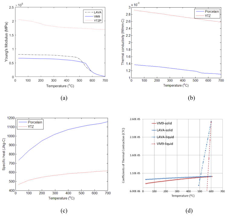
The temperature dependence of Young’s modulus, thermal conductivity, specific heat and coefficients of thermal contraction (CTC) are displayed, respectively, in Figure 1. Bar-shaped porcelain specimens (5 × 5 × 51 mm3) were prepared for CTC measurement using the enameling technique and a disassemblable stainless steel die. The firing cycles followed manufacturers’ specifications. CTC measurements were performed by the Orton Materials Testing & Research Center Westerville, OH). The temperature range was 25 – 708 °C and the heating/cooling rate was 3 °C/min. As plotted in Fig. 1(d), the CTCs for porcelains are divided into solid and liquid CTCs αg(T) and αl (T) given by
Fig. 1.
Temperature-dependent (a) Young’s modulus, (b) thermal conductivity and (c) specific heat profiles used for Y-TZP and porcelains (Zhang et al., 2013), and (d) CTCs for VM9 and LAVA Ceram porcelains. Thermal conductivity and specific heat are assumed to be the same for both VM9 and LAVA Ceram. The CTC for Y-TZP is about 1.03E–05 at room temperature and 1.06E–05 at T=600 °C
| (1) |
where T is in Celsius, and the five coefficients are listed in Table 2.
Table 2.
Constants for thermal contraction coefficients for Y-TZP, VM9 and LAVA Ceram. The constants a, b and c are obtained from the regression analysis. All data is measured by the Orton Materials Testing & Research Center through a paid service.
| Ceramics | a | b | c | d | e |
|---|---|---|---|---|---|
| VM9 | 8.0052E-06 | 4.7623E-09 | −2.2062E–12 | −2.7782E–4 | 5.0500E–7 |
| LAVA Ceram | 9.2057E-06 | 2.0210E-09 | −8.1870E–13 | −7.1464E-5 | 1.6134E–7 |
| Y-TZP | 1.0614E-06 | −1.5188E-08 | 1.2092E–11 | 0 | 0 |
For the core, the thermal contraction strain versus temperature data were fit over the entire range to a third-degree polynomial relation by regression analysis from which αg(T) was determined as a quadratic polynomial. For the veneer, αl(T) was determined by fitting the contraction data with a quadratic equation from the temperature at which creep first occurs on the heating curve to the glass transition temperature, Tg.
2.3 Viscoelastic Finite Element Analysis
Surfaces of the porcelain veneer and zirconia core were digitized into STL (STereoLithography) files. SolidWorks was used to generate 2D surface mesh from the STL file. HyperMesh was used as a preprocessor for ABAQUS to generate 3D 4-node tetrahedron finite element mesh (about 1.7 million elements) from the surface mesh. A sequential dual-step finite element analysis has been performed: heat transfer analysis and viscoelastic stress analysis. In heat transfer analysis, controlled and bench convection cooling were simulated with two convective heat transfer coefficients 1.7E–5 W/mm2 °C (controlled cooling, see DeHoff et al. (2008)) and 0.6E–4 W/mm2 °C (bench cooling), respectively, applied on the surfaces exposed to the air. These cooling rates were equivalent to about 30 °C/min (controlled cooling) and 200 °C/min (bench cooling), and the latter was similar to a typical bench cooling rate of dental prostheses (Zhang et al., 2013). The temperature started from 700 °C where porcelains are in the liquid state and was cooled to 25 °C. Nodal temperatures were calculated at each time step of the heat transfer analysis. In viscoelastic stress analysis, the calculated nodal temperatures were entered as thermal loads into a static analysis step. The zirconia core was assumed as linear elastic while the porcelain veneer was viscoelastic. The user subroutine UEXPAN was developed to calculate thermal strains based on coefficients of thermal contraction of the veneer and the fictive temperature. Rigid body modes were constrained in stress analysis by fixing two adjacent surface nodes in the core. Time domain viscoelasticity is available in Abaqus for small-strain applications. For the material subjected to small shear strain γ (t), the viscoelastic material model defines the shear stress τ (t) as
| (2) |
where GR(t) is the shear relaxation modulus, t is the present time and s is the past time. The normalized shear relaxation modulus can be introduced by
| (3) |
where G0 is the instantaneous shear modulus. The volumetric behavior can be written in a form that is similar to the shear behavior:
| (4) |
where p is the hydrostatic pressure, K0 is the instantaneous elastic bulk modulus, kR(t) is the normalized bulk relaxation modulus assumed to be 1.0 due to its minor influence in most stress states, and εvol is the volume strain. The dimensionless shear relaxation modulus is defined in Abaqus by a Prony series expansion of:
| (5) |
where N is the number of terms (N = 4 used in this study), are coefficients where g1=0.9960, g2=0.0030, g3=0.0006, g4=0.0004, and are shear relaxation times where τ1 = 0.01316, τ2 = 0.1, τ3 = 0.005, τ4 = 0.003 as given at the reference temperature of 700°C (DeHoff et al, 2008).
Figure 2 shows the normalized shear relaxation functions that are approximated using creep testing data at high temperatures (DeHoff et al, 2006). The leftmost solid curve is the master curve at 700 °C. Viscoelastic materials exhibit thermo-rheologically simple temperature behavior. The shift function that represents temperature dependence of shear relaxation functions can be defined using UTRS user subroutine in Abaqus by the Tool-Narayanaswamy approximation, which takes the form (Tool, 1946; Narayanaswamy, 1971)
Fig. 2.
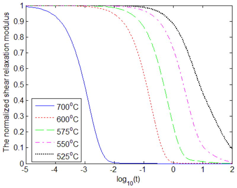
Normalized shear relaxation function at various high temperatures (DeHoff et al., 2006).
| (6) |
where Tref = 973.15 in Kelvin (700 in Celsius), H is the activation energy, R is the ideal gas constant, T(t) is the temperature at time t and Tf(t) is the fictive temperature at time t, and x is a material constant between 0 and 1 (x = 0.27 used, e.g. see DeHoff and Anusavice (2004a)). The logarithmic function ln A(T, Tref, t) shifts the shear relaxation function along the horizontal axis for various temperatures. In the meantime, the volumetric relaxation times are assumed as 1/10 of the shear relation times considering that volume relation of glasses are 4 – 20 times slower than shear relaxation, and that volume relation times have no influence on residual stresses (DeHoff et al., 2006).
The fictive temperature Tf(t) was calculated using the algorithm by Markovsky and Soules (1984). The algorithm is coded in UEXPAN. The thermal strain is given for the core and the veneer, respectively, by
| (7) |
where αg(T) and αl (T) are plotted in Fig. 1(d).
2.4. Fabrication of PVZ bar specimens for experimental validation of VFEM predictions
Y-TZP substrates were CAD/CAM milled out of pre-sintered pucks (Lava™ Plus, 3M ESPE St. Paul, Minnesota) and sintered to a final dimension 10 × 10 × 0.7 mm3. Prior to veneering, the surfaces of zirconia substrates were sandblasted with 50 μm Al2O3 particles for 5 s at a standoff distance of 10 mm and a compressed air pressure of 2 bars. Porcelain veneers were applied using the enameling method by an experienced dental technician (Tanaka et al., 2016). The final thickness of dentin porcelain (VITA VM9 base dentine 3M2, VITA Zahnfabrik, Germany) was 1.5 mm. Six bar-shaped monolithic VM9 porcelain specimens (5 × 5 × 10 mm3) were prepared by the same dental technician using the enameling method and platinum foil molds. The firing cycles for PVZ and monolithic porcelain specimens followed manufacturer’s instruction: the final temperatures were 910 °C for first porcelain firing and 900 °C for second firing. The heating rate was 55 °C/min from 500 °C to final temperature. The holding time at the final sintering temperature was 1 min under vacuum. All specimens were then glaze fired at a heating rate of 60 °C/min from 450 °C to 900 °C, followed by 1 min holding without vacuum. Cooling was carried out by keeping the furnace door closed until reaching 450 °C, which is much below the Tg ~ 600 °C temperature for VM9. Then, the furnace door was gradually opened and the samples were removed from the furnace and cooled in ambient air to room temperature (25 °C). The estimated cooling rate was 32 °C/min from 700 – 450 °C.
The fabricated PVZ plate specimens were cut into two 5.0 mm-wide halves (5 × 10 × 2.2 mm3) using a diamond blade (Isomet 2000, Buehler, Lake Bluff, USA). The cross-section of the PVZ and monolithic porcelain bars was polished to 1 μm finish (Buehler, Lake Bluff, USA). After polishing, a last firing was applied to relieve stresses induced from cutting and polishing so as to establish the residual thermal stresses in PVZ bilayer structures. All samples were subjected individually to the last firing cycle, starting from 450 °C and ending at 700 °C, with a heating rate of 60 °C/min and 1 min holding time. Again, cooling was carried out by keeping the furnace door closed until reaching 450 °C. After that, the furnace door was slowly opened and the sample was removed from the furnace and cooled in ambient air to room temperature. We chose 700 °C for the last firing because it is approximately 100 °C above the reported Tg temperature 600 °C for VM9. In addition, our experiments showed significant creep of VM9 occurred at 710 °C, causing distortion of the veneer/core interface as well as the specimen geometry.
Vickers indentations were performed on the polished surfaces of PVZ bars using a peak load of 4.9 N and a dwell time of 5 s. Three rows of 20 indentations were made: they were located approximately 0.4, 0.8, and 1.3 mm from the veneer/core interface. The Vickers indenter was positioned so that one of its orthogonal axes was oriented parallel to the veneer/core interface, in order to keep corner cracks either parallel or perpendicular to the veneer/core interface. Indentations were separated by at least twice the crack length to prevent interactions. Images of crack patterns were taken immediately after indentation using the microindentation tester imaging system (Leco, St. Joseph MI). Vickers indentations were also placed on polished monolithic porcelain bars, and the resulting crack lengths were used as unstressed reference.
Indentations that caused lateral chipping were excluded from the analysis. The magnitude and sign of the residual stresses (σR) were determined by (Zeng and Rowcliffe, 1994):
| (8) |
where ψ = 1.24 is a crack geometry factor for half-penny cracks (Zeng and Rowcliffe, 1994). C0 and C1 are the indentation crack lengths in unstressed monolithic porcelain and stressed bilayer (core/veneer) specimens, respectively. K1C is the fracture toughness of the porcelain veneer (VM9, Vita Zahnfabrik, K1C= 1.0 MPa·m1/2). The stress value obtained from Eq. 8 may be positive (C1 > C0) or negative (C1 < C0), depending upon whether the stresses are tensile or compressive, respectively, in nature.
3 Results
3.1. Experimental validation of residual stresses of VFEM simulation using PVZ bar specimens
First we demonstrate that residual stresses predicted by VFEM are in dramatically better agreement with experimental measurements than those predicted from LFEM. To illustrate, we adopted a PVZ bilayer bar structure (VM9/Y-TZP, as described above).
Residual stresses normal or tangential to the interface are presented in Fig. 3 as a function of the distance from interface, along the line segment AB. Triangles represent the experimental data, solid and dashed curves represent stress profiles predicted by VFEM and LFEM, respectively. As can be seen, stress profiles predicted by VFEM agree closely with experimental data. The LFEM predictions are, however, not only off by a factor of 3 or more in magnitude but also fail to capture the sign of stresses. Here we demonstrate that VFEM is proven to be very accurate in predicting residual stresses and thus most suitable for identifying key parameters that govern residual stresses in porcelain-veneered prostheses.
Fig. 3.
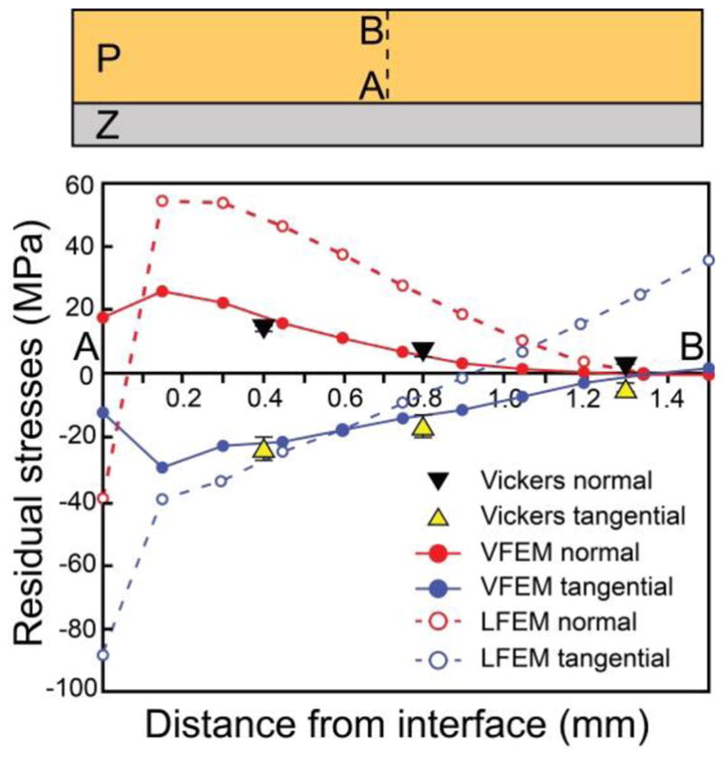
Residual stresses in PVZ bar specimens. Residual stress profiles through porcelain thickness A–B, showing VFEM predictions (solid lines) agreeing closely with experimental data (triangles) relative to LFEM predictions (dashed line).
3.2. Viscoelastic FEA Predictions of Stresses in anatomically-correct PVZ Crowns
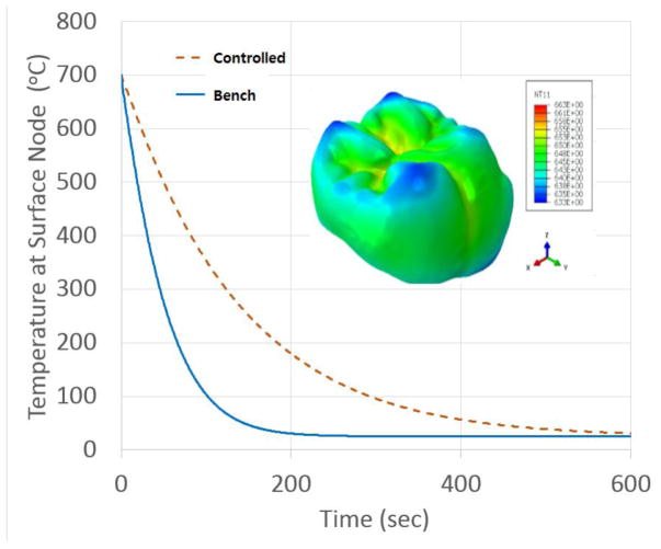
Fig. 4 shows history of surface nodal temperature produced by heat transfer analysis simulated associated with controlled and bench cooling rates with two convective heat transfer coefficients 1.7E–5 W/mm2 C (controlled cooling) and 1.7E–4 W/mm2 C (bench cooling), respectively, applied on the surfaces exposed to the air. Contour of nodal temperature gradients at the controlled cooling is also inserted. [Figure 4]
Fig 4.
Nodal temperature gradient at a surface node in controlled and bench cooling rates. Inset shows the surface temperature profile of a VM9/Y-TZP crown at 10 second into the controlled cooling scheme.
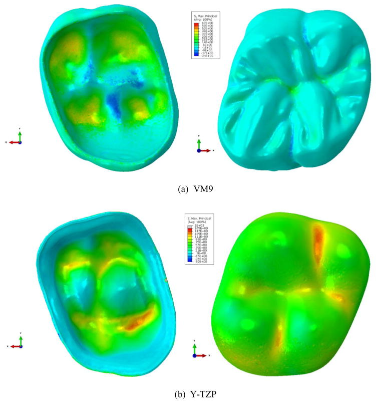
Fig. 5 shows contours of the maximum principal residual stress in the veneer (top) and core (bottom) layers in VM9/Y-TZP subject to the controlled cooling. In the veneer layer, the maximum tensile stress is about 67 MPa near the veneer-core interface as shown in the top-left figure. The concave interface region tends to have tensile maximum principal stress, while the convex region compressive maximum principal stress. In the occlusal surface, central fossa takes larger stress than elsewhere in the exposed veneer surface, and other surface region takes a very low tensile or compressive stress between 6 MPa and 24 MPa. For the core layer, the maximum tensile stress is about 165 MPa. For brevity, all the stress contour plots for the bench cooling rate are not provided and will be collectively summarized in a later section.
Fig. 5.
Contours of the maximum principal stress in the veneer (a) and core (b) layers in VM9/Y-TZP subject to controlled cooling. For veneer layer, the maximum tensile stress is about 67 MPa near the interface. For core layer, the maximum tensile stress is about 165 MPa near the interface and the bottom surface.
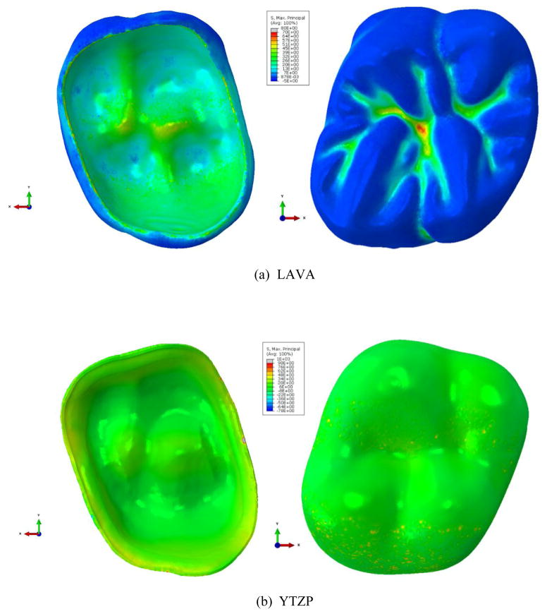
Fig. 6 shows contours of the maximum principal stress in the veneer layer in LAVA/Y-TZP subject to the controlled cooling. The maximum tensile stress is about 70 MPa at central fossa. Groove areas take larger stress than elsewhere in the exposed veneer surface. Contrary to the VM9/Y-TZP model, the convex interface region takes tensile maximum principal stress, while the concave region compressive maximum principal stress. For the core layer, the maximum tensile stress is about 90 MPa.
Fig. 6.
Contours of the maximum principal stress in the veneer (a) and core (b) layers in LAVA/Y-TZP subject to controlled cooling. For veneer layer, the maximum tensile stress is about 70 MPa at central fossa. For core layer, the maximum tensile stress is about 90 MPa near the interface.
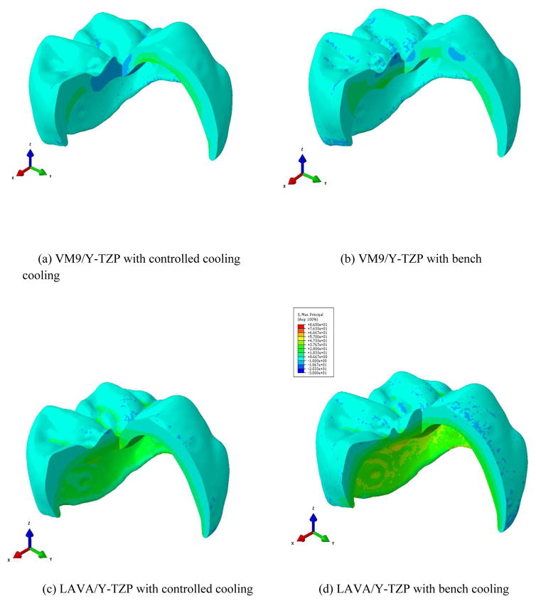
Fig. 7 shows a cross-sectional view of stress variation in veneer thickness in VM9/Y-TZP and LAVA/Y-TZP models subject to bench and controlled cooling rates. Through-thickness transition of positive and negative maximum principal stresses is observed. Bench cooling led to higher maximum principal stresses in the whole region than controlled cooling.
Fig. 7.
A cut view of the veneer layer in VM9/Y-TZP subject to (a) controlled and (b) bench cooling, whereas LAVA/Y-TZP systems subject to (c) controlled and (d) bench cooling.
4. Discussions
We have developed a VFEM model to capture residual stress profiles in PVZ crown systems. The residual stresses predicted by the VFEM model have been validated in a flat simple PVZ bilayer structure. It showed much better agreement with the experimental measurements than the LFEM simulations reported in our previous manuscript (Tanaka et al., 2016). The main issue with the LFEM is its inability to capture the viscoelastic behavior of porcelain. At temperatures above the Tg temperature of porcelain, the modulus of porcelain not only depends on temperature, but also on time. It means that even when the temperature is held constant, the modulus reduces dramatically with time following a well-known decaying exponential function. Even though the coefficient of thermal contraction of liquid-state porcelain is much larger than that of solid-state porcelain (indicating a larger thermal strain), the resultant stress becomes smaller than the LEFM predicts. Due to the deficiency of LEFM to capture the temperature and time-dependent phenomenon of stress relaxation, in order to get a relatively small stress value, LFEM often assumes a very small coefficient of thermal contraction of liquid porcelain, in some cases 3 – 4 times smaller than the actual CTC of the liquid porcelain. The advantage of viscoelasticity is to provide shear stress relaxation at any high temperatures. The dependence of shear relaxation modulus on the time-dependent temperature in a specimen is described by a simple shift function (Eq. (5)), supported by experimentally determined creep data (DeHoff and Anusavice, 2004a). It is important to note that the shear relaxation modulus data presented in Fig. 3 is universal for porcelains at any given temperature under cooling rates examined here.
Our viscoelastic analysis has shown for materials with similar densities that residual stresses are less sensitive to thermal conductivity (k) and specific heat (c) values. In fact, the k and c values for various dental porcelains are very similar. In the interest of simplicity, we assume similar thermal conductivity and specific heat properties for VM9 and LAVA Ceram. Thus, the significant combined effect of thermal contraction coefficients and Young’s modulus on the residual stress can be elucidated. For the controlled cooling rate, the maximum tensile stresses 67 MPa and 165 MPa occurred in the veneer-core interface and core layers, respectively, of VM9/Y-TZP. On the other hand, 70 MPa and 90 MPa occurred in the central fossa and core layer, respectively, of LAVA/Y-TZP. For bench cooling, the maximum tensile stresses 70 MPa and 222 MPa occurred in the veneer-core interface and core layer, respectively, of VM9/Y-TZP. 86 MPa and 168 MPa occurred in the veneer-core interface and core layer, respectively, of LAVA/Y-TZP. The veneer layer in VM9/Y-TZP exhibits a little less maximum residual stress than that of LAVA/Y-TZP, but the region where it occurs is near the veneer-core interface for VM9/Y-TZP while at the central fossa for LAVA/Y-TZP. Our findings show that a combination of small CTC mismatch and a low porcelain modulus results in lower residual stresses for a given cooling rate, and these two material parameters interplay in determining residual stresses.
It is noted that thermal expansion coefficients and Young’s modulus can affect the location and the magnitude of the maximum tensile stress. We also observe that a higher maximum tensile stress occurs in the core layer of VM9/Y-TZP than that of LAVA/Y-TZP. This is not crucial, however, due to very high core layer strength. As expected, the bench cooling causes the increase of residual stress in both layers of the two systems. Thus, the choice of the veneer material and the cooling protocol used makes a significant influence in the residual stress profiles in dental crowns.
Some limitations of the present study are discussed herein. Controlled and bench convection cooling were simulated using constant convective heat transfer coefficients. These coefficients may not be constant and can be varied in time to match with realistic cooling conditions. However, our VFEM model can accommodate any cooling profiles by specifying convective coefficients. In addition, the volumetric relaxation times are assumed to be 1/10 of the shear relation times (DeHoff et al., 2006) and thus have no major influence on residual stresses. Finally, damage or crack formation is not considered during this viscoelastic analysis. Further study on the effect of crack initiation and growth on deformations and residual stresses will require damage analysis in conjunction with the present analysis.
5. Conclusions
Based on the current VFEM analysis to determine residual stresses in PVZ crown systems, the following conclusions may be drawn:
Using a simple flat PVZ model system, our experimental residual stress measurements using the Vickers indentation method have clearly demonstrated that residual stresses predicted by VFEM are in dramatically better agreement with experimental measurements than those predicted from LFEM.
A smaller CTC mismatch between porcelain veneer and zirconia core, as well as a lower porcelain modulus can effectively reduce residual stresses in both veneer and core layers for any given cooling rates.
A slower cooling rate results in lower residual stresses in both porcelain veneer and zirconia core layers.
Acknowledgments
This work was sponsored by funding from the United States National Institute of Dental & Craniofacial Research, National Institutes of Health (Grants Nos. 1R01 DE026279, R01DE026772 and R01DE017925).
Footnotes
Conflict of Interest
All authors declare no conflict of interest.
Publisher's Disclaimer: This is a PDF file of an unedited manuscript that has been accepted for publication. As a service to our customers we are providing this early version of the manuscript. The manuscript will undergo copyediting, typesetting, and review of the resulting proof before it is published in its final citable form. Please note that during the production process errors may be discovered which could affect the content, and all legal disclaimers that apply to the journal pertain.
References
- Asaoka K, Kuwayama N, Tesk JA. Influence of tempering method on residual stress in dental porcelain. Journal of dental Research. 1992;71:1623–1627. doi: 10.1177/00220345920710091501. [DOI] [PubMed] [Google Scholar]
- Asaoka K, Tesk JA. Transient and residual stress in a porcelain-metal strip. Journal of dental Research. 1900;69:463–469. doi: 10.1177/00220345900690020901. [DOI] [PubMed] [Google Scholar]
- Baldassarri M, Stappert CFJ, Wolff MS, Thompson VP, Zhang Y. Residual stresses in porcelain-veneered zirconia prostheses. Dental Materials. 2012;28:873–879. doi: 10.1016/j.dental.2012.04.019. [DOI] [PMC free article] [PubMed] [Google Scholar]
- Belli R, Monteiro S, Baratieri LN, et al. A photoelastic assessment of residual stresses in zirconia-veneer crowns. Journal of Dental Research. 2012;91(3):316–20. doi: 10.1177/0022034511435100. [DOI] [PubMed] [Google Scholar]
- Benetti P, Kelly JR, Sanchez M, Della Bona A. Influence of thermal gradients on stress state of veneered restorations. Dental Materials. 2014;30(5):554–63. doi: 10.1016/j.dental.2014.02.020. [DOI] [PubMed] [Google Scholar]
- Choi JE, Waddell JN, Swain MV. Pressed ceramics onto zirconia. Part 2: indentation fracture and influence of cooling rate on residual stresses. Dental Materials. 2011;27:1111–1118. doi: 10.1016/j.dental.2011.08.003. [DOI] [PubMed] [Google Scholar]
- Christensen GJ. Porcelain-fused-to-metal versus zirconia-based ceramic restorations. J Am Dent Assoc. 2009;140(8):1036–9. doi: 10.14219/jada.archive.2009.0316. [DOI] [PubMed] [Google Scholar]
- DeHoff PH, Anusavice KJ. Effect of visco-elastic behavior on stress development in a metal-ceramic system. Journal of Dental Research. 1989a;68:1223–1230. doi: 10.1177/00220345890680080201. [DOI] [PubMed] [Google Scholar]
- DeHoff PH, Anusavice KJ. Tempering stresses in feldspathic porcelain. Journal of Dental Research. 1989b;68:134–138. doi: 10.1177/00220345890680020701. [DOI] [PubMed] [Google Scholar]
- DeHoff PH, Anusavice KJ. Analysis of tempering stresses in bilayered porcelain discs. Journal of Dental Research. 1992;71(5):1139–1144. doi: 10.1177/00220345920710050201. [DOI] [PubMed] [Google Scholar]
- DeHoff PH, Anusavice KJ. Creep functions of dental ceramics measured in a beam-bending viscometer. Dental Materials. 2004a;20:297–304. doi: 10.1016/S0109-5641(03)00107-6. [DOI] [PubMed] [Google Scholar]
- DeHoff PH, Anusavice KJ. Shear stress relaxation of dental ceramics determined from creep behavior. Dental Materials. 2004b;20:717–725. doi: 10.1016/j.dental.2003.10.005. [DOI] [PubMed] [Google Scholar]
- DeHoff PH, Anusavice KJ, Gotzen N. Viscoelastic finite element analysis of an all-ceramic fixed partial denture. Journal of Biomechanics. 2006;39:40–48. doi: 10.1016/j.jbiomech.2004.11.007. [DOI] [PubMed] [Google Scholar]
- DeHoff PH, Barrett AA, Lee RB, Anusavice KJ. Thermal compatibility of dental ceramic systems using cylindrical and spherical geometries. Dental Materials. 2008;24:744–752. doi: 10.1016/j.dental.2007.08.008. [DOI] [PMC free article] [PubMed] [Google Scholar]
- DeHoff PH, Vontivillu SB, Wang Z, Anusavice KJ. Stress relaxation behavior of dental porcelains at high temperatures. Dental Materials. 1994;10:178, 184. doi: 10.1016/0109-5641(94)90029-9. [DOI] [PubMed] [Google Scholar]
- Denry I, Kelly JR. State of the art of zirconia for dental applications. Dent Mater. 2008;24(3):299–307. doi: 10.1016/j.dental.2007.05.007. [DOI] [PubMed] [Google Scholar]
- Hermann I, Bhowmick S, Zhang Y, Lawn BR. Competing fracture modes in brittle materials subject to concentrated cyclic loading in liquid environments: Trilayer structures. Journal of Materials Research. 2006;21:512–521. [Google Scholar]
- Mainjot AK, Schajer GS, Vanheusden AJ, Sadoun MJ. Residual stress measurement in veneering ceramic by hole-drilling. Dental Materials. 2011;27:439–444. doi: 10.1016/j.dental.2010.12.002. [DOI] [PubMed] [Google Scholar]
- Markovsky A, Soules TF. An efficient and stable algorithm for calculating fictive temperatures. Journal of American Ceramic Society. 1984;67:C56–C57. [Google Scholar]
- Meira JBC, Reis BR, Tanaka CB, Ballester RY, Cesar P, Versluis A, Swain MV. Residual stresses in Y-TZP crowns due to changes in the thermal contraction coefficient of veneers. Dental materials. 2013;29:594–601. doi: 10.1016/j.dental.2013.03.012. [DOI] [PubMed] [Google Scholar]
- Nakatsuka A, Anusavice KJ. Finite element analysis of stress distribution in porcelain discs. Journal of Materials Science. 1997;32:3621–3627. [Google Scholar]
- Narayanaswamy OS. A model of Structural Relaxation in Glass. J Am Ceram Soc. 1971;54:491–498. [Google Scholar]
- Pang Z, Chughtai A, Sailer I, Zhang Y. A fractographic study of clinically retrieved zirconia-ceramic and metal-ceramic fixed dental prostheses. Dent Materials. 2015;31(10):1198–206. doi: 10.1016/j.dental.2015.07.003. [DOI] [PMC free article] [PubMed] [Google Scholar]
- Sailer I, Feher A, Filser F, et al. Five-year clinical results of zirconia frameworks for posterior fixed partial dentures. Int J Prosthodont. 2007;20(4):383–8. [PubMed] [Google Scholar]
- Taskonak B, Mecholsky JJ, Jr, Anusavice KJ. Residual stresses in bilayer dental ceramics. Biomaterials. 2005;26:3235–3241. doi: 10.1016/j.biomaterials.2004.08.025. [DOI] [PubMed] [Google Scholar]
- Tanaka CB, Harisha H, Baldassarri M, Wolff MS, Tong H, Meira JBC, Zhang Y. Experimental and Finite Element Study of Residual Thermal Stresses in Veneered Y-TZP Structures. Ceramics International. 2016;42:9214–9221. doi: 10.1016/j.ceramint.2016.03.018. [DOI] [PMC free article] [PubMed] [Google Scholar]
- Tholey MJ, Swain MV, Thiel N. Thermal gradients and residual stresses in veneered Y-TZP frameworks. Dental Materials. 2011;27:1102–1110. doi: 10.1016/j.dental.2011.08.001. [DOI] [PubMed] [Google Scholar]
- Tool AQ. Relation between inelastic deformability and thermal expansion of glass in its annealing range. Journal of the American Ceramic Society. 1946;29:240–253. [Google Scholar]
- Zeng KY, Rowcliffe D. Experimental-Measurement of Residual-Stress Field around a Sharp Indentation in Class. Journal of the American Ceramic Society, 1994. 1994;77(2):524–530. [Google Scholar]
- Zhang Z, Guazzato M, Sornsuwan T, Scherrer SS, Rungsiyakull C, Li W, Swain MV, Li Q. Thermally induced fracture for core-veneered dental ceramic structures. Acta Biomaterialia. 2013;9:8394–8420. doi: 10.1016/j.actbio.2013.05.009. [DOI] [PubMed] [Google Scholar]
- Zhang Y, Chai H, Lee JJ, Lawn BR. Chipping resistance of graded zirconia ceramics for dental crowns. J Dent Res. 2012;91(3):311–5. doi: 10.1177/0022034511434356. [DOI] [PMC free article] [PubMed] [Google Scholar]
- Zhang Y, Sailer I, Lawn BR. Fatigue of dental ceramics. Journal of Dentistry. 2013;41(12):1135–1147. doi: 10.1016/j.jdent.2013.10.007. [DOI] [PMC free article] [PubMed] [Google Scholar]


