Abstract
In this article, we present an overview on the thermocatalytic reaction of hydrogen peroxide (HO) gas on a manganese (IV) oxide (MnO) catalytic structure. The principle of operation and manufacturing techniques are introduced for a calorimetric HO gas sensor based on porous MnO. Results from surface analyses by X-ray photoelectron spectroscopy (XPS) and scanning electron microscopy (SEM) of the catalytic material provide indication of the HO dissociation reaction schemes. The correlation between theory and the experiments is documented in numerical models of the catalytic reaction. The aim of the numerical models is to provide further information on the reaction kinetics and performance enhancement of the porous MnO catalyst.
Keywords: hydrogen peroxide, manganese (IV) oxide, catalytic decomposition, calorimetric gas sensor, numerical simulation
1. Introduction
Manganese (IV) oxide (MnO) is a tetravalent oxide compound of manganese that is commonly found in nature in the form of pyrolusite mineral [1]. MnO is thermally stable up to a temperature of about 500 C, above which thermal decomposition takes place and MnO transforms to the trivalent manganese oxide (Mn2O3) [1,2]. Due to the high activity and thermal stability of MnO, catalysts made of the bulk material or from a dispersion are widely used in various industrial sectors such as hydrogenation of ethylene or in dry cell batteries as the primary component of the cathode mixture [1,2]. An extensively studied application of MnO is in space programs, where it is used as a catalyst for hydrogen peroxide (HO)-based fuels [3,4]. In these fuel cells MnO catalysts have a high activity that induces an exothermic decomposition reaction of hydrogen peroxide containing solutions [5,6,7,8] or gases [9,10,11,12].
Hydrogen peroxide (HO) is known for its strong and fast acting microbicidal properties due to the formation of various radical species that lead to several types of cell damage [13,14,15,16]. Concentrated HO solutions (≥35% w/w) are established sterilization agents in the food and pharmaceutical aseptic packaging industries, where a high level of disinfection is required [15,17]. A common sterilization procedure for packaging surfaces prior to filling of perishable products at atmospheric conditions is by applying a high-temperature gas mixture of air and gaseous HO with volumetric concentrations up to 8% v/v and temperatures up to 300 C [12,15,18]. To produce the HO containing gas, a certain quantity of aqueous HO solution (35% w/w) is mixed with sterile air and passed through heated channels of a heat exchanger that is designed as an evaporation unit [19].
HO is known for its unstable nature [3,20] and various stabilizing chemicals are added to prevent uncontrolled decomposition caused by the presence of impurities from the production process [14,21]. These stabilizing agents include phosphates, colloids and chelating agents that bind with the impurities to prevent catalytic decomposition of HO [22]. In accordance to the Food and Drug Administration (FDA) Code of Federal Regulations title 21 (21CFR178.1005), the amount of inorganic impurities including stabilizing agents has to meet the specifications set by the Food Chemicals Codex (FCC). Table 1 indicates the allowed level of inorganic impurities as defined by the FCC [23]. The type and concentration of impurities depend on the HO production process and the same holds for stabilizing agents that are chosen in function of the HO application method (bath, spray or vapor sterilization).
Table 1.
Specifications of hydrogen peroxide solution for indirect use in food processing.
| Parameter | Specification |
|---|---|
| Phosphate | ≤0.005% w/w |
| Iron | ≤0.5 mg/kg |
| Tin | ≤10 mg/kg |
| Lead | ≤4 mg/kg |
| Residue on evaporation | ≤0.006% w/w |
The decomposition reaction of HO is a highly exothermic reaction [4,11]. While the auto-thermal decomposition of HO (described in literature as homogeneous decomposition) dominantly occurs at temperatures above 400 C [24,25], catalysts can be used to lower the activation energy of the decomposition process [26]. Hence, HO decomposition reaction can occur at any temperature (described in literature as heterogeneous decomposition) and about 105 kJ/mol is released [25,27,28].
During the evaporation process of aqueous HO solution in the evaporation unit and dependent on the surface temperature of the fluid channels comprising the evaporation unit, some of the HO stabilizing agents are deposited on the internal surfaces of the evaporation unit. This results in a depletion of original stabilizing agents’ concentration in the HO gas. Consequently, the quantification of HO volumetric concentration exiting an evaporation unit at high temperatures can be unreliable by using conventional analytical methods. In order to maintain a high quality of the final packaged product, a constant sterility assurance level (SAL) must be maintained [13]. In addition to temperature, process time and surrounding humidity, the concentration of the sterilant gas must be kept constant throughout the decontamination process [21,29]. Here, a continuous quantification of HO gas concentration required for sterilization can be achieved by the development of innovative sensing methods and devices.
Recently, several types of HO sensing principles have been studied and reported in the literature. An example of these sensing principles include nanozyme-based colorimetric sensors based on vanadium dioxide (VO2) nanofibers [30] or commercially available test kits such as Quantofix (Macherey-Nagel GmbH & Co., KG, Düren, Germany). Moreover, electrochemical sensors have been developed such as a sensor based on platinum nanoparticles [31]. However, these sensor types detect HO concentrations in solutions.
To monitor gaseous HO concentrations, further electrochemical sensors are commercially available, such as Dräger Polytron® 7000 or Vaisala PEROXCAP® sensor. However, these sensor types measure the HO concentration enriched in an electrolyte, which is not applicable under elevated temperature conditions >70 C.
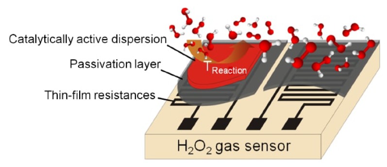
Consequently, another sensor type to monitor and determine the concentration of gaseous HO at elevated temperatures as applied during sterilization processes in aseptic filling machines is based on the calorimetric principle. Such calorimetric sensors have been previously developed in our research institute [10,12,18,19,27,32,33,34,35,36]. Hereby, a differential calorimetric sensor set-up was concepted, fabricated and tested to monitor the concentration of HO containing gas at elevated temperatures. The design of the sensor (schematically shown in Figure 1) is based on two equal temperature sensing elements fabricated on a substrate surface. MnO powder (Merck KGaA, Darmstadt, Germany) acting as the catalytic material is then deposited on top of one of the sensing elements defining the active sensing element to HO, while the other sensing element is specially passivated against HO.
Figure 1.
Design of the differential set-up of a calorimetric gas sensor consisting of two chemically passivated thin-film meander sensing elements. One element measures the gas temperature as a reference signal and the other element measures the temperature rise due to an exothermic catalytic decomposition of HO. Reproduced with permission from [35]. John Wiley and Sons, Inc., 2012.
At the catalytically activated element HO decomposes to water vapor and oxygen and heat is released in this process. Thereby, the active sensing element records a higher temperature signal than the passive element. By monitoring the temperature difference between the active and passive sensing element, quantification of the released thermal energy on the catalytic surface is possible. The fraction of HO in the gas atmosphere can hence be derived and the concentration logged [26,32]. As a result, calorimetric HO sensors based on MnO present a method for the detection, quantification and monitoring of the HO-rich environment required in aseptic filling machines.
There is a wide range of catalysts that decompose HO. For instance, metallic oxides of lead, silver, cobalt, copper and iron have been reported to decompose HO vapor [9]. Group VIII metals including platinum, palladium and rhodium exhibit exothermic decomposition reactions with HO solutions [37]. Additionally, catalysts of platinum, palladium and silver supported on aluminum oxide are reported to decompose HO vapor [38]. Porous heterogeneous catalytic structures made of oxides of manganese (MnO) are also commonly researched HO catalysts [5,8,39]. In the last decade, catalytic structures based on MnO are tested as a compatible active substance of calorimetric HO gas sensors [12,36,40].
A variety of decomposition reaction schemes between HO and the MnO catalyst has been proposed in literature [5,11,20]. Equations (1)–(5) provide the most probable reaction pathway of catalytic HO decomposition [5,9,12,20,38]. After a convective mass transport of chemicals to the catalyst surface, the HO molecule is adsorbed on the surface sites [4,41]. The reaction hence starts with electron exchange (Equation (1)) between the HO molecule and MnO, where a perhydroxyl (HO2·) radical is formed in the process [7,14,38]. The next step involves chain propagation, where hydroxyl (HO·) radical (Equation (2)) and additional HO2· are formed (Equation (3)). As a final step the catalyst is replenished (Equation (4)).
| (1) |
| (2) |
| (3) |
| (4) |
Furthermore, a water molecule is formed as the product of the reaction between a hydroxide and a hydrogen ion as presented in Equation (5). An alternative reaction pathway involves the reaction between HO· and HO2· radicals as shown in Equation (6) [33].
| (5) |
| (6) |
The reaction scheme in Equation (1) indicates a change in the oxidation state of the manganese from Mn4+ as in MnO to Mn3+ as in Mn2O3, which correlates with various observations in literature [8,11,12,39,42]. It is also reported that the change in the oxidation state is accompanied by a decrease of the catalytic activity [8]. This can be explained by examining the activation energy of the decomposition of HO on Mn2O3, which resides at a value of 77.1 kJ/mol [42]. The activation energy of the decomposition of HO on MnO is reported to be around 50 kJ/mol [43]. Additionally, the catalyst replenishment reaction shown in Equation (4) requires an electron donor that comes in the form of an HO· radical. Nonetheless, the radical is also used in other reactions as seen in Equation (3) and Equation (6). Therefore, by favoring Equation (3) over the catalyst replenishment (Equation (4)) a decrease of catalyst activity can be expected. In addition to the decrease of activity, catalyst poisoning might occur due to the presence of stabilizing agents in the sterilant gas that can cover the surface of the catalyst preventing the contact with HO gas [44]. Both factors might affect the sensitivity of the calorimetric sensor to HO gas.
In general, the overall catalytic decomposition reaction of HO on a heterogeneous catalyst is mostly expressed in literature as a single-step reaction by neglecting the intermediate products [3,8,39]. In this context, HO is directly converted to its final products and a first-order reaction takes place as expressed in Equation (7). The global reaction rate constant (k) of this reaction is determined by an Arrhenius law (Equation (8)). It is worth mentioning that other reaction schemes for the decomposition of HO can follow another reaction order. For example, Satterfield and Stein [25] derived a reaction order of 3/2 for the homogeneous decomposition of HO by proposing a different reaction steps than presented in Equations (2) and (3). A review by Garwig [3] of the heterogeneous decomposition of HO with different inorganic solid catalysts show that the reaction follows first-order kinetics.
| (7) |
| (8) |
In Equation (8), is the pre-exponential or frequency factor (usually described in 1/s), is the activation energy of the reaction in J/(kg·K), R is the universal gas constant (8.314 J/(mol·K)) and T is the temperature of the reactant at the Kelvin scale. Table 2 introduces the parameters ( and ) that describe the reaction kinetics as reported in prior literature articles. Using the noted reaction parameters, the k value was derived for the decomposition reaction of HO containing gas at a temperature of 270 C (543.15 K).
Table 2.
Summary of reaction kinetics as reported in literature and the derived reaction rate (k) at a gas temperature of 270 C (543.15 K).
Additionally, the , and k values are reported in literature to relate to the state of HO (liquid or gas) during decomposition and to the dimension and material of the catalyst [39,49]. The large deviation in the pre-exponential factor leads to a deviation in the rate of catalytic decomposition reaction. Therefore, the nature of the catalytic material and its surface including the distribution and size of the nano-porous particles of the MnO play a role in the rate kinetics.
In this work, an analysis of a calorimetric HO sensor and its MnO-catalyst structure will be presented. Also the surface characterization of the employed MnO catalyst by X-ray photoelectron spectroscopy (XPS) and by scanning electron microscopy (SEM) will be addressed. Also, changes in the MnO catalyst due to HO decomposition are noted and discussed. To explain the operational principle of the calorimetric HO gas sensor, an exemplary response curve is introduced and analyzed. In the sequel of this work, numerical modeling based on finite-element-method (FEM) combined with SEM images is applied to derive characteristic properties of the porous MnO-catalyst structure. This is achieved by analyzing the flow through the catalytic structure at the micro-scale to derive the porosity and permeability values of the porous material. Finally, the decomposition reaction is then numerically analyzed at the macro-scale by using the derived characteristics of the porous layer to provide further insight on the reaction through the MnO catalyst.
2. Calorimetric HO Sensor
2.1. Design
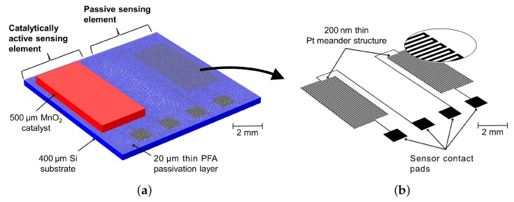
The design of the calorimetric HO sensor is shown in Figure 2. For detailed information on the fabrication process we refer to refs. [33,34]. The functional layers of the calorimetric sensor are deposited onto a 400 m thin silicon (Si) substrate with a 500 nm thin silicon oxide (SiO2) layer. Physical vapor deposition is used to deposit a layer of 20 nm titanium (Ti) and 200 nm platinum (Pt). The Ti layer acts as an adhesive between the SiO2 and Pt layers. The meander temperature sensing elements are then patterned by a conventional lithography process [33]. Due to the reactivity of HO on Pt [37], the temperature elements are passivated with a 20 m layer of perfluoralkoxy (PFA) material via spin-coating followed by thermal curing. At this point, the sensor is capable of measuring the temperature of a HO-rich environment or flow. To complete the differential design of the calorimetric sensor principle, a dispersion containing MnO particles in the range of 10 to 100 m embedded in an adhesive such as SU-8 (MicroChem Inc., Westborough, MA, USA), is developed on top of one of the passivated Pt sensing elements via drop-coating followed by thermal curing. The final thickness of the catalyst is about 500 m.
Figure 2.
(a) Design and dimensions of the developed calorimetric HO sensor based on a Si substrate (blue). The differential set-up consists of sensing elements made of Pt covered with PFA layer. A MnO-catalyst structure (red) is deposited on top of one sensing element to act as sensing element for HO; (b) Design of the meander Pt structure (black) that is located underneath the PFA passivation layer. Reproduced with permission from [28]. John Wiley and Sons, Inc., 2017.
The result of the fabrication process is a differential set-up that represents the calorimetric HO sensor. The passive side of the sensor will measure the temperature of the HO-rich gas, while a catalytic exothermic decomposition reaction occurs on the active sensor side releasing heat. The difference in temperature read-out between the passive and the active Pt resistance correlates to the concentration of HO gas in the atmosphere or gas flow.
2.2. Sensor Measurements
In the last decade, different configurations of the calorimetric HO gas sensor have been developed and characterized. Näther et al. [19] introduced a differential sensor set-up consisting of two temperature detectors (one catalytically activated and the other one passivated). The work showed a proof-of-concept for a calorimetric detection principle of HO gas in industrial aseptic filling machines. To miniaturize the sensor set-up, monolithic thin-film thermopile sensors based on Si substrate have been developed [32]. To further increase the performance of the sensor, such as the sensitivity toward HO gas, a set of temperature resistors was fabricated on a Si substrate [10]. The corresponding sensor configuration is depicted in Figure 2. With this sensor configuration different types of catalysts (Pd, MnO and platinum black (Pt)) as the active sensing element have been studied [10]. In a later work, different polymer-based passivation materials have been characterized [35]. From the published response behavior of these sensors it has been concluded that the sensor with MnO catalyst and PFA passivation layer provides the highest sensitivity. To further improve the sensor application and sensitivity the sensor configuration has been fabricated on a flexible polyimide film as the sensor substrate [33,34].
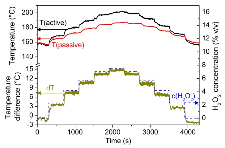
An exemplary response graph of such a calorimetric HO gas sensor is shown in Figure 3. Hereby, a stream containing HO gas is regulated to a predefined temperature and is directed toward the surface of the sensor placed 5 cm below the exit nozzle of the evaporation unit of a sterilization test rig (as described in [19,32]). As explained in Section 2.1, a catalytic exothermic reaction takes place on the MnO catalyst which is located on top of one of the sensing elements. The amount of heat released by the exothermic reaction is proportional to the HO gas concentration in the stream or in the surrounding environment. On the one hand, a step-wise change in the recorded temperature signal of the catalytically active sensing element is observed (black curve). On the other hand, the passive sensing element exhibits a similar but lower step-wise change in the recorded temperature signal (red curve). Nonetheless, due to the passivation of the sensing elements by PFA material an exothermic reaction on the passive sensing element does not occur. Therefore, the recorded temperature increase is due to the heating by the gas stream and the conductive heat transfer from the catalytically active sensing element. The temperature difference between the signal of the two sensing elements correlates to the concentration of HO gas. As a result, sensor response graphs similar to the one presented in Figure 3 can be used to obtain a calibration curve and a response function for determining the HO concentration.
Figure 3.
Response graph of a HO gas sensor. The upper part of the graph shows the recorded temperature value from the catalytically active sensing element (black) and the passive sensing element (red). The lower half of the graph shows a step-wise change in the HO concentration (c(HO) in dashed blue with the scale to the right) in an outlet stream and the resulting temperature difference (dT in green) as the output signal from the differential sensor set-up (T(active)–T(passive)).
2.3. Scanning Electron Microscopy (SEM)
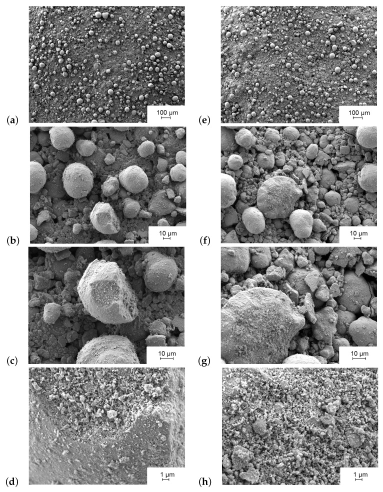
Figure 4 shows the SEM characterization (JSM-7800F, Joel Ltd., Akishima, Tokyo, Japan) of the MnO catalytic layer at different magnification levels and in different states. The first state shown in Figure 4a–d represents the catalytic layer after fabrication and prior to the conditioning with HO gas (Solvay, INTEROX® AG Spray 35S). The surface of the catalyst at this point shows the MnO particles in bright contrast to the surface. The difference in contrast is related to the surface roughness and hence the rate of electron dispersion. Therein, the catalyst is a mixture of MnO particles embedded in an adhesive matrix of SU-8 [12]. Prior to coming in contact with HO in a process called sensor conditioning, the catalyst exhibits a surface that is mostly darker (see Figure 4b) than after HO contact (see Figure 4f). The reason is dominantly due to the adhesive layer that covers the catalyst surface resulted from thermal curing of the MnO emulsion. The results of the current SEM characterization match previously published observations presented in ref. [12].
Figure 4.
Scanning electron micrographs of MnO catalytic layer after fabrication (a–d) and after surface conditioning with 8% v/v HO at a temperature of 270 C (e–h).
Figure 4e–h depicts the catalytic surface after conditioning with 8% v/v HO containing gas for more than 4 h at a gas temperature of 270 C, similar to the procedure explained in ref. [12]. At first glance the particles of MnO seem to be sharper defined as compared to the images taken prior to HO conditioning. SEM characterization shows an increase in the surface roughness and the protrusion of MnO particles. One possible reason is the removal of the adhesive layer of SU-8 that partially overlaps the MnO particles due to the exothermic decomposition of HO on the MnO surface. A probable removal mechanism is by the oxidative stress formed from HO vapor, which is comparable to oxygen plasma cleaning as stated in ref. [12]. Additionally, the catalytic decomposition reaction of HO on the sensor surface releases a high level of thermal energy (about 105 kJ/mol), which leads to a localized temperature increase of the MnO particle’s surface before dissipating to the rest of the catalyst body and the sensor chip. Hence, we observe that the adhesive SU-8 layer diminishes by the HO decomposition process. This can be due to the thermal stability limit of SU-8 material (about 380 C [50]) that is reached by exothermic decomposition of HO near the material. Finally, the overall decomposition reaction (Equation (7)) releases gaseous species (water vapor and oxygen) that, if developed in the region between MnO particles, the adhesive layer can peel off.
Figure 4d,h present the nanoporous structure of the MnO catalyst. The high surface porosity and the scale of porous surface assure a large surface area of the catalyst and explain the high reactivity of the MnO catalyst to HO gas compared to other tested materials (see ref. [10]). The effect of HO gas treatment is also notable on the nanoporous structure of MnO particle. The surface roughness of a MnO particle after peroxide treatment (see Figure 4h) is more pronounced than before the treatment (see Figure 4d).
2.4. X-ray Photoelectron Spectroscopy (XPS)
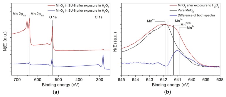
The surface characterization of the MnO catalyst prior and after the exposure to HO vapor was performed by high resolution XPS analysis using 5600 LS electron spectrometer (Physical Electronics, Inc., Chanhassen, MN, USA) equipped with a small-spot X-ray source providing monochromatic Al K photons. Figure 5a represents the first set of experimental data that aim to analyze the effect of HO vapor exposure on the surface of the dispersion containing the MnO catalyst. Figure 5b presents the second set of experiments that aim at studying the effect of HO decomposition on the oxidative state of MnO.
Figure 5.
XPS scans of (a) dispersion of MnO powder in a SU-8 matrix before (bottom curve, blue) and after (top curve, red) exposure to HO vapor and (b) magnification of the Mn 2p peak to assess the state of the MnO catalyst before (bottom curve) and after (top curve) exposure to HO vapor. Reproduced with permission from [12]. John Wiley and Sons, Inc., 2014.
The spectroscopic results in Figure 5a prior and after HO exposure show peaks at binding energy levels of 652.8 eV and 641.2 eV, respectively. These levels can be assigned to the photoelectrons emitted from the Mn 2p core doublet. A peak at the binding energy of 528.8 eV indicates the presence of oxygen atoms. These peaks are stronger after conditioning the catalyst with HO gas. When we take a look at the peak at the binding energy of 287 eV that presents carbon atoms we notice a smaller peak level after conditioning with HO accompanied by an increase in the peak of the binding energy related to the Mn atom. Therefore, the XPS analysis confirms the observation made in Section 2.3 regarding the presence of a thin polymer layer of SU-8 that suppresses the Mn signal of the MnO catalyst before the exposition to HO gas.
Figure 5b is a high resolution scan focusing on the Mn 2p region in order to assess the oxidation state of Mn before and after contact with HO gas. Prior to coming in contact with HO gas, the XPS analysis of the catalyst shows a peak around the binding level of Mn4+ that indicates manganese (IV) oxide. After catalyst exposure to HO gas, the peak widens and covers different energy levels. These levels indicate a change in oxidation state of MnO to Mn2O3 [12]. The change in oxidative state confirms the decomposition reaction pathway described by Equation (1).
3. Numerical Models
In Section 3.1 numerical modeling is used to analyze the catalytic surface on the micro level. Later on, results from micro-level characterization will be used as an input to evaluate the decomposition reaction of HO containing gas on the macro level (Section 3.2). The term “micro” relates to the catalytic bulk surface and not to the surface of a single MnO particle. While the term “macro” represents the catalyst with a thickness of about 500 m (see Figure 2).
3.1. Surface Characteristics of the Nanoporous Catalyst
The sensitivity of the calorimetric sensor to HO gas is affected by different physical parameters related to the nature of the catalyst. The surface porosity () and permeability () are two characteristics of a catalyst and its surface. The porosity describes the volumetric or surface ratio of voids in-between the particles and the total volume or surface of catalyst [51]. When the porosity reaches a value of 0, the catalyst is a solid structure, while a porosity value higher than 80% describes a fibrous material [51,52]. The permeability quantifies the resistance of the material for a fluid flow. Hence, an increase in permeability induces higher volumetric flow rates that enhance mass transport of materials and the rate of catalytic reaction. However, the permeability of the MnO catalyst is dependent on different factors such as the geometric irregularity of the particles, their size distribution and the arrangement of the channels [53]. This leads to different catalysts with similar porosity value but a different permeability value. For these reasons, direct correlation between the porosity and permeability variables is not straightforward to derive [53].
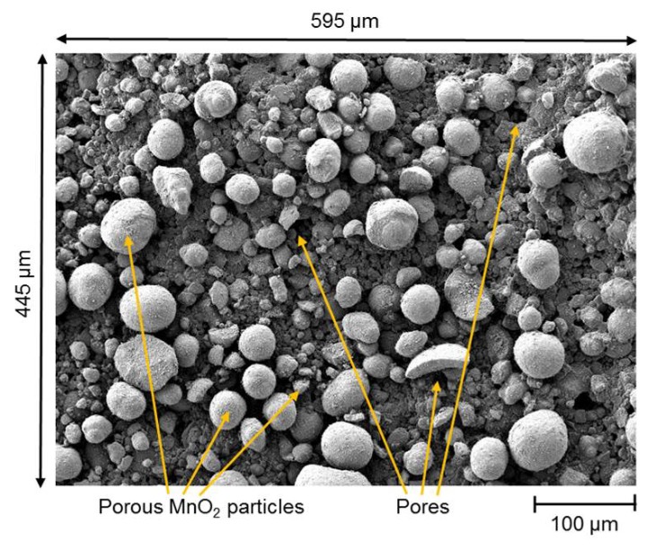
In this work, numerical modeling of a creeping flow on the surface of the MnO catalyst was used to determine the values of and for the catalytic surface. The value of for the layer is determined as the ratio of the area between the catalyst particles to the total surface of the layer. Figure 6 shows a typical SEM image of the catalytic structure prior to the conditioning with HO. The image was chosen due to the clear grey scale contrast between the MnO particles and the floor of the chip surface. Here, the SEM image is assumed to be representative for the surface of the functionalized chip. Therefore, to determine the surface area, Figure 6 was imported to a numerical FEM software COMSOL Multiphysics® (Comsol Multiphysics GmbH, Göttingen, Germany).
Figure 6.
Close-up SEM image of the porous MnO catalyst showing MnO particles in bright color and the catalyst floor made of the MnO dispersion in dark gray.
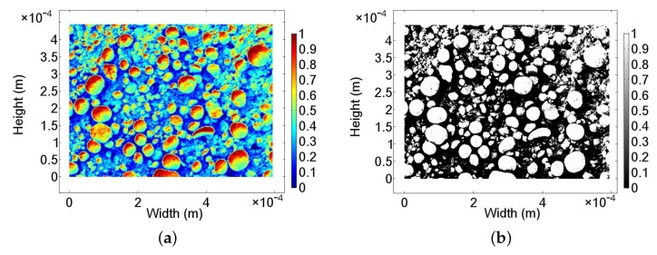
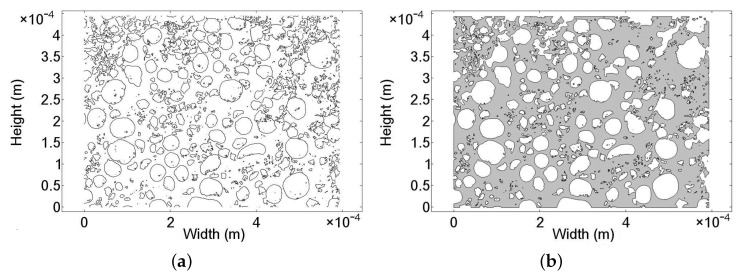
A representation of the SEM photo after importing to the numerical model is given in Figure 7a. The color contrast of the SEM image is representative to a normalized height profile of the catalyst. The bright end of the color scale (value > 0.5) shown in Figure 7a indicates MnO particles, while the dark regions (value < 0.5) of the spectrum imply their absence and the pore regions. To determine the value of and , the particle-free region is of interest. Hence, the regions containing MnO particles are filtered out, resulting in the structure shown in Figure 7b. Subsequently, the contour of the MnO particles is defined by the lines at singular value of 0.5. The final particle contours are presented in Figure 8a. The porous flow region is derived from a geometric Boolean operation between the contour lines of the particle and a rectangular domain with identical dimension to the layer. Due to the complexity and the level of geometric details, some geometric parts of the catalytic surface are lost. However, the level of lost details is small in comparison to the overall structural dimensions. As a result, the porous flow region of MnO catalyst is approximated numerically in Figure 8b.
Figure 7.
SEM images: (a) after importing to the numerical software and defining a color spectrum and (b) filtered surface of the MnO particle layer.
Figure 8.
(a) Contour of the MnO particle and (b) numerical domain for flow simulation representing the particle-free region.
The dimensions of the SEM image (Figure 6) are 594 m in width and 445 m in height, making a total surface area of 0.26 mm. The surface integration of Figure 8b produces a value of 0.16 mm. Thus, the resultant porosity of the surface structure can be calculated as 61%.
To derive the permeability of the porous structure, the transversal flow through the catalyst is numerically solved. Darcy’s law (see Equation (9)) is used to resolve the medium flow through a porous material driven by a pressure difference [53,54]. Using numerical methods and Equation (9), the value of the catalytic structure can be derived. An empirical form of Darcy’s law is presented in Equation (10).
| (9) |
| (10) |
Here, and are the resolved Darcy velocity and its field in m/s, respectively. The parameter is the dynamic viscosity of the fluid in Pa·s, P is the pressure value in Pa and is the coordinate axes. For a two-dimensional model, is the pressure difference derived from the boundaries of the model in Pa and is the length the flow travels from inlet to outlet boundaries (width of the model) in m. represents the overall bulk velocity (Darcy velocity) of the flow in m/s, which is derived by dividing the volumetric flow rate or Darcy flux (resulted from flow simulation) over the inlet surface area of the model.
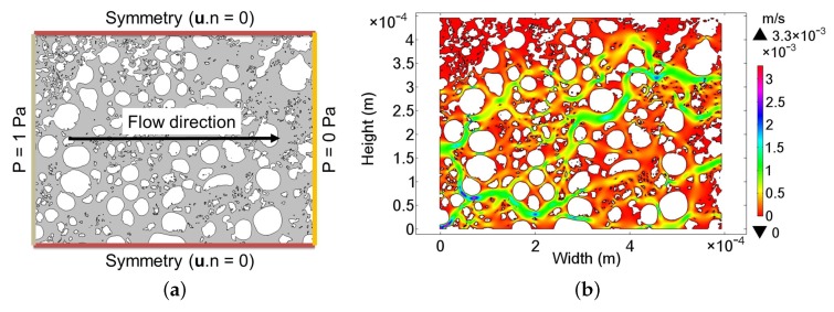
Equation (9) is valid for low laminar flow rates when inertial terms are negligible [53]. The linear relation between the pressure difference and velocity (see Equation (10)) means that any pressure value can be used as long as the numerical solver remains stable and the flow is dominantly laminar. Therefore, since the permeability of the catalytic surface is a characteristic of the layer and is independent of the volumetric flow rate of the medium, an exemplary pressure difference of 1 Pa was utilized. The set-up of the numerical laminar flow model is schematically presented in Figure 9a with symmetry flow condition defined on the upper and lower border of the geometry to introduce the flow continuity condition.
Figure 9.
(a) Schematic diagram of the numerical simulation design and (b) result of an 8% v/v HO containing gas flow simulation with a pressure difference of 1 Pa.
To produce a HO concentration of 8% v/v out of an evaporation unit, 300 L/s HO solution 35% w/w is mixed with 2.5 m/h air at 20 C and heated to an exit temperature of 270 C. The density of the HO containing gas mixture is about 625 g/m with a dynamic viscosity of about 2.4 Pa·s. Figure 9b shows the numerical result of the velocity distribution using isothermal material properties and solving the laminar flow for a pressure difference of 1 Pa. Solving Equation (10) results in a permeability value of = 2.1 m.
3.2. Decomposition of HO with Porous MnO Catalyst
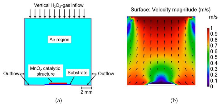
In this section, the simulation results of the and values from the previous surface analysis of the catalyst are used to reflect the properties of the bulk porous catalyst. For this purpose, the ratio of pores (see Figure 6) in the bulk catalyst is assumed to be similar to the ratio of voids between MnO particles on the catalyst surface. In this context, a first hand approximation to analyze a HO sensor structure subjected to a perpendicular flow of gaseous HO, as for conventional sensor measurement [28]. Thereby, the values of and through the catalyst structure are the previously derived values in the case of parallel flow direction (presented in Section 3.1). Hence, a homogenized two-dimensional (2D) model of the sensor is employed to analyze the HO decomposition reaction. Figure 10a overviews the design of the homogenized 2D model that is used to analyze the sensor position relative to a flow of HO containing gas. Due to the undetermined flow condition during sensor operation, an exemplary flow of 1 m/s at 270 C was presumed perpendicular to the surface of the catalyst.
Figure 10.
(a) Design of the numerical models representing a side view of the catalytic MnO structure (red) placed on top of a substrate (blue) with a vertical flow direction perpendicular to the sensor surface; (b) Result of the numerical model indicating the flow profile and direction.
Figure 10b shows the numerical result of the flow simulation. The perpendicular flow over the catalyst surface induces a pressure region that causes a decrease of velocity above the catalyst and the formation of a stagnation region above the sensor surface. The decrease of velocity impedes the mass transport of HO. Nevertheless, mass transport to the catalyst is not only governed by a convective turbulent flow, but also by the diffusion of material as defined by the steady-state Fick’s first law of diffusion given in Equation (11).
| (11) |
In Equation (11), D is the binary diffusion coefficient of HO, determined for the current HO containing gas by applying the Chapman-Enskog theory; for justification and detailed derivation we refer to ref. [28]. The variable represents the velocity in m/s, c is the concentration of HO in the flow in mol/m, and k is the reaction rate in 1/s. At a HO temperature of 270 C, the value of D is m/s.
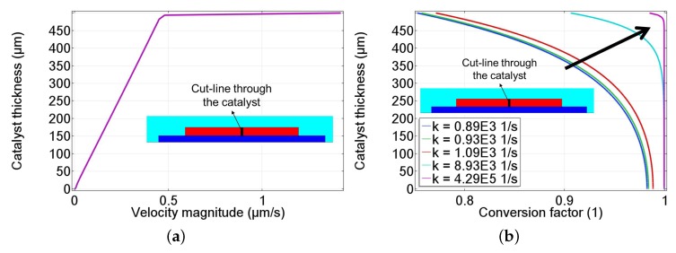
Figure 11a depicts the velocity profile across the mid of the catalyst (refered to as cut-line). Due to the porosity and permeability of the porous catalyst, the flow decreases through the catalyst reaching a value of 0 m/s at the substrate surface. Additionally, due to the uncertainty of the Arrhenius pre-exponential parameter () indicated in Table 2, a parametric sweep of the value of k is analyzed. Figure 11b shows the conversion factor of HO through the catalyst center (cut-line). The conversion factor describes the amount of reacted HO through the catalyst. A conversion factor of 1 represents the depletion of all HO in the catalyst. It is observed that with an increase in the value of k (in the direction of the black arrow), the reaction occurs dominantly on the surface of the catalyst. This indicates a dominant surface decomposition reaction as observed in previous modeling attempts of the full three-dimensional (3D) sensor model described in ref. [28].
Figure 11.
Plots of the numerical model through the center of the 500 m MnO catalyst showing (a) the velocity magnitude in m/s and (b) the conversion factor of HO due to the catalytic decomposition reaction through the catalyst by varying the reaction rate (k) that increase in the direction of black arrow.
4. Conclusions
A short review on the catalytic decomposition reaction of HO on MnO catalyst was presented. The differential design of a calorimetric HO gas sensor was introduced and the thermocatalytic sensor principle was explained by an exemplary sensor response curve. The MnO catalyst was studied by SEM and XPS. XPS analyses indicate a change of oxidation state of the MnO catalyst which is on par with the decomposition scheme of HO. On the one hand, SEM analyses show a change in the roughness of the MnO catalyst surface after conditioning with HO gas. On the other hand, XPS analyses result in a difference in the strength of the recorded signals before and after the conditioning process. The XPS analyses confirm the made observation from SEM analyses that the SU-8 overlayer is removed by HO exposure. A numerical model that solves Darcy’s law on a geometry built from SEM analyses was used to derive physical parameters of the MnO catalyst, which include the surface porosity and permeability to HO containing gas. Later, a homogenized 2D model was designed to study the effect of the MnO catalyst’s reaction rate on the rate of HO conversion in the catalyst material. In a future extension of this work, combining the presented analysis method and three-dimensional sensor modeling described in ref. [28], a more precise model for a calorimetric HO sensor can be achieved.
Acknowledgments
This work was financially supported by the European Union and by the State of North Rhine-Westphalia within the operational program EFRE.NRW 2014-2020, project “EfficientSterile”. D. Rolka is acknowledged for the SEM characterization. Hans-Gerd Boyen is acknowledged for the XPS characterization.
Author Contributions
Z.B.J. designed the FEM simulations and contributed to the data analysis. P.K. designed the sensor. P.K. and J.O. fabricated and characterized the sensor together with data analysis. J.O. and P.K. characterized and analyzed the catalytic surface with SEM and XPS. P.H.W. and M.J.S. have been supervising, discussing the experiments and edited the presented work.
Conflicts of Interest
The authors declare no conflict of interest. The founding sponsors had no role in the design of the study; in the collection, analyses, or interpretation of data; in the writing of the manuscript, and in the decision to publish the results.
References
- 1.Pisarczyk K. Manganese compounds. In: Kroschwitz J.I., Seidel A., Kirk R.E., Othmer D.F., editors. Kirk-Othmer Encyclopedia of Chemical Technology. Wiley-Interscience; Hoboken, NJ, USA: 2005. [Google Scholar]
- 2.Kappenstein C., Zaki M.I. X-ray photoelectron spectroscopy and diffractometry of MnOx catalysts: Surface to bulk composition relationships. Zeitschrift für Physikalische Chemie. 1992;176:97–116. [Google Scholar]
- 3.Garwig P.L. Heterogeneous decomposition of H2O2 by inorganic catalysts: Technical report AFRPL-TR-66-136, 1966
- 4.Koopmans R.J., Shrimpton J.S., Roberts G.T. Validation and design optimizaton for a hydrogen peroxide thruster; Proceedings of the 47th AIAA/ASME/SAE/ASEE Joint Propulsion Conference and Exhibit; San Diego, CA, USA. 31 July–03 August 2011; Reston, VA, USA: American Institute of Aeronautics and Astronautics; 2011. [Google Scholar]
- 5.Broughton D.B., Wentworth R.L. Mechanism of decomposition of hydrogen peroxide solutions with manganese dioxide. I. J. Am. Chem. Soc. 1947;69:741–744. doi: 10.1021/ja01196a003. [DOI] [PubMed] [Google Scholar]
- 6.Lee Y.N., Lago R.M., Fierro J.L.G., González J. Hydrogen peroxide decomposition over Ln1−xAxMnO3 (Ln = La or Nd and A = K or Sr) perovskites. Appl. Catal. A Gen. 2001;215:245–256. doi: 10.1016/S0926-860X(01)00536-1. [DOI] [Google Scholar]
- 7.Do S.H., Batchelor B., Lee H.K., Kong S.H. Hydrogen peroxide decomposition on manganese oxide (pyrolusite): Kinetics, intermediates, and mechanism. Chemosphere. 2009;75:8–12. doi: 10.1016/j.chemosphere.2008.11.075. [DOI] [PubMed] [Google Scholar]
- 8.Hasan M.A., Zaki M.I., Pasupulety L., Kumari K. Promotion of the hydrogen peroxide decomposition activity of manganese oxide catalysts. Appl. Catal. A Gen. 1999;181:171–179. doi: 10.1016/S0926-860X(98)00430-X. [DOI] [Google Scholar]
- 9.Hart A.B., McFadyen J., Ross R.A. Solid-oxide-catalyzed decomposition of hydrogen peroxide vapor. Trans. Faraday Soc. 1963;59:1458–1469. doi: 10.1039/tf9635901458. [DOI] [Google Scholar]
- 10.Kirchner P., Li B., Spelthahn H., Henkel H., Schneider A., Friedrich P., Kolstad J., Keusgen M., Schöning M.J. Thin-film calorimetric H2O2 gas sensor for the validation of germicidal effectivity in aseptic filling processes. Sens. Actuators B Chem. 2011;154:257–263. doi: 10.1016/j.snb.2010.01.058. [DOI] [Google Scholar]
- 11.Micoli L., Bagnasco G., Turco M., Trifuoggi M., Russo Sorge A., Fanelli E., Pernice P., Aronne A. Vapor phase H2O2 decomposition on Mn based monolithic catalysts synthesized by innovative procedures. Appl. Catal. B Environ. 2013;140–141:516–522. doi: 10.1016/j.apcatb.2013.04.072. [DOI] [Google Scholar]
- 12.Oberländer J., Kirchner P., Boyen H.G., Schöning M.J. Detection of hydrogen peroxide vapor by use of manganese(IV) oxide as catalyst for calorimetric gas sensors. Phys. Status Solidi A. 2014;211:1372–1376. doi: 10.1002/pssa.201330359. [DOI] [Google Scholar]
- 13.Agalloco J.P., Akers J.E., editors. Advanced Aseptic Processing Technology. CRC Press; Boca Raton, FL, USA: 2010. Drugs and the Pharmaceutical Sciences. [Google Scholar]
- 14.Petri B.G., Watts R.J., Teel A.L., Huling S.G., Brown R.A. Fundamentals of ISCO using hydrogen peroxide. In: Siegrist R.L., Crimi M., Simpkin T.J., editors. In Situ Chemical Oxidation for Groundwater Remediation. Volume 3. Springer; New York, NY, USA: 2011. pp. 33–88. SERDP/ESTCP Environmental Remediation Technology. [Google Scholar]
- 15.Kačer P., Švrček J., Syslová K., Václavík J., Pavlík D., Červený J., Kuzma M. Vapor phase hydrogen peroxide—method for decontamination of surfaces and working areas from organic pollutants. In: Puzyn T., editor. Organic Pollutants Ten Years after the Stockholm Convention: Environmental and Analytical Update. InTech; Rijeka, Croatia: 2012. [Google Scholar]
- 16.Heckert R.A., Best M., Jordan L.T., Dulac G.C., Eddington D.L., Sterritt W.G. Efficacy of vaporized hydrogen peroxide against exotic animal viruses. Appl. Environ. Microbiol. 1997;63:3916–3918. doi: 10.1128/aem.63.10.3916-3918.1997. [DOI] [PMC free article] [PubMed] [Google Scholar]
- 17.Ansari I.A., Datta A.K. An overview of sterilization methods for packaging materials used in aseptic packaging systems. Food Bioprod. Process. 2003;81:57–65. doi: 10.1205/096030803765208670. [DOI] [Google Scholar]
- 18.Kirchner P., Oberländer J., Suso H.P., Rysstad G., Keusgen M., Schöning M.J. Monitoring the microbicidal effectiveness of gaseous hydrogen peroxide in sterilization processes by means of a calorimetric gas sensor. Food Control. 2013;31:530–538. doi: 10.1016/j.foodcont.2012.11.048. [DOI] [Google Scholar]
- 19.Näther N., Juárez L.M., Emmerich R., Berger J., Friedrich P., Schöning M.J. Detection of hydrogen peroxide (H2O2) at exposed temperatures for industrial processes. Sensors. 2006;6:308–317. doi: 10.3390/s6040308. [DOI] [Google Scholar]
- 20.Satterfield C.N., Stein T. Decomposition of hydrogen peroxide vapor on relatively inert surfaces. Ind. Eng. Chem. 1957;49:1173–1180. doi: 10.1021/ie50571a042. [DOI] [Google Scholar]
- 21.Fraise A.P., Maillard J.Y., Sattar S.A., editors. Principles and Practice of Disinfection, Preservation, and Sterilization. 5th ed. John Wiley & Sons; Chichester, UK: 2012. [Google Scholar]
- 22.Kirk R.E., Othmer D.F., editors. Encyclopedia of Chemical Technology. Volume 13 Wiley; New York, NY, USA: 2003. [Google Scholar]
- 23.USP United States Pharmacopeial Convention . Food Chemicals Codex. 9th ed. USP United States Pharmacopeial Convention; Rockville, MD, USA: 2014. [Google Scholar]
- 24.Giguère P.A. The thermal decomposition of hydrogen peroxide vapor. II. Can. J. Res. 1947;25b:135–150. doi: 10.1139/cjr47b-018. [DOI] [PubMed] [Google Scholar]
- 25.Satterfield C.N., Stein T.W. Homogeneous decomposition of hydrogen peroxide vapor. J. Phys. Chem. 1957;61:537–540. doi: 10.1021/j150551a006. [DOI] [Google Scholar]
- 26.Bársony I., Dücso C., Fürjes P. Thermometric gas sensing. In: Comini E., Faglia G., Sberveglieri G., editors. Solid State Gas Sensing. Springer US; Boston, MA, USA: 2009. pp. 1–24. [Google Scholar]
- 27.Oberländer J., Kirchner P., Keusgen M., Schöning M.J. Strategies in developing thin-film sensors for monitoring aseptic food processes: Theoretical considerations and investigations of passivation materials. Electrochim. Acta. 2015;183:130–136. doi: 10.1016/j.electacta.2015.06.126. [DOI] [Google Scholar]
- 28.Jildeh Z.B., Kirchner P., Oberländer J., Kremers A., Wagner T., Wagner P.H., Schöning M.J. FEM-based modeling of a calorimetric gas sensor for hydrogen peroxide monitoring. Phys. Status Solidi A. 2017;214 doi: 10.1002/pssa.201600912. [DOI] [Google Scholar]
- 29.McDonnell G.E., Sheard D. A Practical Guide to Decontamination in Healthcare. John Wiley & Sons, Ltd.; Hoboken, NJ, USA: 2012. [Google Scholar]
- 30.Tian R., Sun J., Qi Y., Zhang B., Guo S., Zhao M. Influence of VO2 nanoparticle morphology on the colorimetric assay of H2O2 and glucose. Nanomaterials. 2017;7:347. doi: 10.3390/nano7110347. [DOI] [PMC free article] [PubMed] [Google Scholar]
- 31.Li Y., Su Z., Wei G., Xie G., Zhang M., Zhang X. Nanoporous carbon nanofibers decorated with platinum nanoparticles for non-enzymatic electrochemical sensing of H2O2. Nanomaterials. 2015;5:1891–1905. doi: 10.3390/nano5041891. [DOI] [PMC free article] [PubMed] [Google Scholar]
- 32.Kirchner P., Ng Y.A., Spelthahn H., Schneider A., Henkel H., Friedrich P., Kolstad J., Berger J., Keusgen M., Schöning M.J. Gas sensor investigation based on a catalytically activated thin-film thermopile for H2O2 detection. Phys. Status Solidi A. 2010;207:787–792. doi: 10.1002/pssa.200983309. [DOI] [Google Scholar]
- 33.Kirchner P., Oberländer J., Friedrich P., Berger J., Suso H.P., Kupyna A., Keusgen M., Schöning M.J. Optimization and fabrication of a calorimetric gas sensor built up on a polyimide substrate for H2O2 monitoring. Phys. Status Solidi A. 2011;208:1235–1240. doi: 10.1002/pssa.201001132. [DOI] [Google Scholar]
- 34.Kirchner P., Oberländer J., Friedrich P., Berger J., Rysstad G., Keusgen M., Schöning M.J. Realization of a calorimetric gas sensor on polyimide foil for applications in aseptic food industry. Sens. Actuators B Chem. 2012;170:60–66. doi: 10.1016/j.snb.2011.01.032. [DOI] [Google Scholar]
- 35.Kirchner P., Reisert S., Pütz P., Keusgen M., Schöning M.J. Characterization of polymeric materials as passivation layer for calorimetric H2O2 gas sensors. Phys. Status Solidi A. 2012;209:859–863. doi: 10.1002/pssa.201100773. [DOI] [Google Scholar]
- 36.Kirchner P. Ph.D. Thesis. Fachbereich Pharmazie, Phillips-Universität Marburg; Marburg/Lahn, Germany: 2013. Calorimetric Gas Sensors for Hydrogen Peroxide Monitoring in Aseptic Food Processes. [Google Scholar]
- 37.McKee D. Catalytic decomposition of hydrogen peroxide by metals and alloys of the platinum group. J. Catal. 1969;14:355–364. doi: 10.1016/0021-9517(69)90326-1. [DOI] [Google Scholar]
- 38.Ono Y., Matsumura T., Kitajima N., Fukuzumi S. Formation of superoxide ion during the decomposition of hydrogen peroxide on supported metals. J. Phys. Chem. 1977;81:1307–1311. doi: 10.1021/j100528a018. [DOI] [Google Scholar]
- 39.Sorge A.R., Turco M., Pilone G., Bagnasco G. Decomposition of hydrogen peroxide on MnO2/TiO2 catalysts. J. Propuls. Power. 2004;20:1069–1075. doi: 10.2514/1.2490. [DOI] [Google Scholar]
- 40.Nakayama M., Sato A., Yamaguchi R. Decomposition and detection of hydrogen peroxide using sigma-MnO2 thin film electrode with self-healing property. Electroanalysis. 2013;26:2283–2288. [Google Scholar]
- 41.Lin S.S., Gurol M.D. Catalytic decomposition of hydrogen peroxide on iron oxide: Kinetics, mechanism, and implications. Environ. Sci. Technol. 1998;32:1417–1423. doi: 10.1021/es970648k. [DOI] [Google Scholar]
- 42.Zaki M.I., Hasan M.A., Pasupulety L., Kumari K. Bulk and surface characteristics of pure and alkalized Mn2O3: TG, IR, XRD, XPS, specific adsorption and redox catalytic studies. N. J. Chem. 1998;22:875–882. doi: 10.1039/a800796i. [DOI] [Google Scholar]
- 43.Krejci D., Woschnak A. Hydrogen peroxide decomposition for micro propulsion: Simulation and experimental verification; Proceedings of the 47th AIAA/ASME/SAE/ASEE Joint Propulsion Conference and Exhibit; San Diego, CA, USA. 31 July–3 August 2011; Reston, VA, USA: American Institute of Aeronautics and Astronautics; 2011. [Google Scholar]
- 44.Jang D., Kwon S., Jo S. Effect of phosphate stabilizers in hydrogen peroxide decomposition on manganese-based catalysts. J. Propuls. Power. 2015;31:904–911. doi: 10.2514/1.B35310. [DOI] [Google Scholar]
- 45.Zhou X., Hitt D.L. One-dimensional modeling of catalyzed H2O2 decomposition in microchannel flows; Proceedings of the 33rd AIAA Fluid Dynamics Conference and Exhibit; Orlando, FL, USA. 23–26 June 2003; Reston, VA, USA: American Institute of Aeronautics and Astronautics; 2003. [Google Scholar]
- 46.Koopmans R.J., Shrimpton J.S., Roberts G.T. Parametric studies for a hydrogen peroxide rocket engine; Proceedings of the 4th European Conference for Aerospace Sciences EUCASS; Saint Petersburg, Russia. 4–8 July 2011. [Google Scholar]
- 47.Widdis S.J., Hitt D.L., Asante K., Cross M.W., Varhue W.J., McDevitt M.R. Computational and experimental studies of catalytic H2O2 decomposition in microscale reactors; Proceedings of the 43rd AIAA Thermophysics Conference; New Orleans, LA, USA. 25–28 June 2012; Reston, VA, USA: American Institute of Aeronautics and Astronautics; 2012. [Google Scholar]
- 48.Widdis S.J., Asante K., Hitt D.L., Cross M.W., Varhue W.J., McDevitt M.R. A MEMS-based catalytic microreactor for a H2O2 monopropellant micropropulsion system. IEEE/ASME Trans. Mechatron. 2013;18:1250–1258. doi: 10.1109/TMECH.2013.2249085. [DOI] [Google Scholar]
- 49.Koopmans R.J. Ph.D. Thesis. University of Southampton; Southampton, UK: 2013. Modelling of Multiphase Multicomponent Chemically Reacting Flows through Packed Beds. [Google Scholar]
- 50.Martinez-Duarte R., Madou M. SU-8 photolithography and its impact on microfluidics. In: Mitra S.K., Chakraborty S., editors. Microfluidics and Nanofluidics Handbook. CRC Press; Roca Raton, FL, USA: 2012. pp. 231–268. [Google Scholar]
- 51.Lewis R.W., Nithiarasu P., Seetharamu K.N. Fundamentals of the Finite Element Method for Heat and Fluid Flow. John Wiley & Sons, Ltd.; Chichester, UK: 2004. [Google Scholar]
- 52.Cahela D.R., Tatarchuk B.J. Permeability of sintered microfibrous composites for heterogeneous catalysis and other chemical processing opportunities. Catal. Today. 2001;69:33–39. doi: 10.1016/S0920-5861(01)00352-2. [DOI] [Google Scholar]
- 53.Costa A. Permeability-porosity relationship: A reexamination of the Kozeny-Carman equation based on a fractal pore-space geometry assumption. Geophys. Res. Lett. 2006;33:1–5. doi: 10.1029/2005GL025134. [DOI] [Google Scholar]
- 54.Foumeny E.A., Pahlevanzadeh H. Evaluation of plug flow assumption in packed beds. Chem. Eng. Technol. 1990;13:161–171. doi: 10.1002/ceat.270130123. [DOI] [Google Scholar]


