Abstract
Background
The purpose of this study was to evaluate the accuracy of fitting of an implant supported screw-retained bar made on definitive casts produced by 4 different dental stone products.
Material and Methods
The dental stones tested were QuickRock (Protechno), FujiRock (GC), Jade Stone (Whip Mix) and Moldasynt (Heraeus). Three external hexagon implants were placed in a polyoxymethylene block. Definitive impressions were made using monophase high viscosity polyvinylsiloxane in combination with custom trays. Then, definitive models from the different types of dental stones were fabricated. Three castable cylinders with a machined non-enganging base were cast and connected with a very small quantity of PMMA to a cast bar, which was used to verify the marginal discrepancies between the abutments and the prosthetic platforms of the implants. For that purpose special software and a camera mounted on an optical microscope were used. The gap was measured by taking 10 measurements on each abutment, after the Sheffield test was applied. Twelve definitive casts were fabricated for each gypsum product and 40 measurements were performed for each cast. Mean, minimum, and maximum values were calculated. The Shapiro-Wilk test of normality was performed. Mann-Whitney test (P<.06) was used for the statistical analysis of the measurements.
Results
The non-parametric Kruskal-Wallis test revealed a statistically significant effect of the stone factor on the marginal discrepancy for all Sheffield test combinations: 1. Abutment 2 when screw was fastened on abutment 1 (χ2=3, df=35.33, P<0.01), 2. Abutment 3 when the screw was fastened on abutment 1 (χ2=3, df=37.74, P<0.01), 3. Abutment 1 when the screw was fastened on abutment 3 (χ2=3, df=39.79, P<0.01), 4. Abutment 2 when the screw was fastened on abutment 3 (χ2=3, df=37.26, P<0.01).
Conclusions
A significant correlation exists between marginal discrepancy and different dental gypsum products used for the fabrication of definitive casts for implant supported bars. The smallest marginal discrepancy was noted on implant supported bars fabricated on definitive casts made by Type III mounting stone. The biggest marginal discrepancy was noted on implant supported bars fabricated on definitive casts made by Type V dental stone. The marginal discrepancies presented on implant supported bars fabricated on definitive casts made by two types of Type IV dental stone were not significantly different.
Key words:Dental implant, passive fit, dental stones, marginal discrepancy.
Introduction
Dental implants have been efficiently used for the rehabilitation of partially and completely edentulous patients, for more than thirty years. Predictable long term results have been achieved for both fixed and removable implant supported prostheses (1-8).
One of the major issues arising when more than one implants are restored is that of passive fit. The term ‘passive fit’ refers to the simultaneous sitting of all marginal points of a prosthesis on the corresponding transmucosal abutments or on the prosthetic platforms of the implants if castable cylinder abutments have been used. A requirement for a passive fit is the absence of any stress in the prosthesis/abutment/screw/implant complex, when functional or parafunctional loads are not exerted on the system. In the absence of this prerequisite technical complications may arise. These include screw loosening and/or fracture, as well as abutment, prosthesis and implant fractures (1,7,9-24). Furthermore, the biological complications that may occur include discomfort or pain to the patient and bone loss (4,7,25-36).
Several methods have been proposed in order to evaluate the passivity of the fit of an implant supported prosthesis. These include visual, tactile and radiographical methods, as well as use of disclosing agents, strain gauges, patient feedback and the Sheffield test. The latter is probably the method which is most commonly used. It refers to the complete fastening of one terminal screw and the examination of the fitting of the prosthesis on all other abutments to which the corresponding screws have not been fastened (37,38). The above methods are subjective and they rely on the clinical experience of the operator.
Most of the testing procedures focus on the gap between the prosthesis and the transmucosal abutments or between the prosthesis and the implants, if castable cylinders have been used. The acceptable marginal opening associated with the existence of a passive fit has changed over the years. In 1983, P-I Brånemark considered that 10μm was the maximum acceptable opening between the prosthesis and the transmucosal abutments (2). The 10μm limit as a maximum marginal discrepancy is also supported by Romero et al. and Abduo and Lyons (39,40). However, Klineberg and Murray have supported the notion that the existence of a 30μm opening in 10% of the abutment-implant interface is clinically acceptable (41). In 1992, Assif et al.have proposed that 26 μm is an acceptable marginal opening, while Jemt in 1991 and Yanase et al. in 1994 have concluded that the marginal opening should be 150μm or less (10,37,42). To date, there is no consensus regarding both the definition of ‘passive fit’ and the method which should be employed in order to evaluate the framework passivity (40,43-49).
Traditional fabrication of implant supported prostheses requires use of definitive casts made of dental stones. It has been demonstrated that the technique and the materials employed are very important for the accuracy of the definitive cast (50-54). Several materials, including epoxy resins, have been used in the past in an effort to improve the properties of the definitive casts, specifically surface hardness, resistance to abrasion, and detail reproduction (55-58). However, one of the major problems encountered was the polymerization shrinkage which led to pronounced dimensional instability (59). Usually, type IV and V dental stones are employed for the fabrication of the definitive casts (60-64). A characteristic of dental stones is their expansion during the setting process. The expansion varies depending on the type of stone used, and it ranges between 0.08% and 0.2% (65). Generally, almost 75% of the setting expansion observed in the first 24 hours occurs in the first hour (66). However, it has been demonstrated that setting expansion continues for a period of 96 hours (67,68). This setting expansion does not contribute to inaccuracies which will have as an effect the absence of a passive fit of a prosthesis onto the supporting implants (62), while others claim the opposite (69,70).
The purpose of the present study was to evaluate in vitro the accuracy of fitting of an implant supported screw-retained bar made on definitive casts produced by 4 different dental stone products. The null hypothesis was that the accuracy of fitting of the implant supported bar would not be affected by the different dental stone products.
Material and Methods
Four dental stone products were included in this in vitro study ( Table 1). These dental stones were chosen because they are widely used in both the United States and the European Union.
Table 1. Dental Stones Studied.
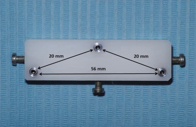
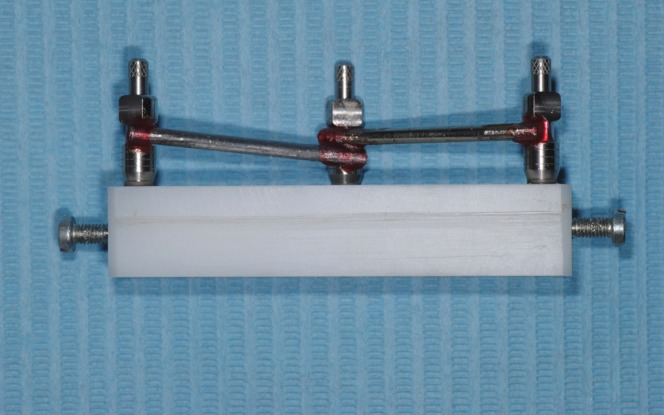
A 64×18×12 mm polyoxymethylene (Tecaform AH; Ensigner Inc, Washington, PA) block with a hardness of 145MPa and a modulus of elasticity of 2800MPa, was fabricated for the purposes of this study. An industrial milling machine (WMW Machinery Co) was used to drill three parallel to each other sites, with a diameter of 3.20 mm and a depth of 8 mm. Three 3.25/4.00, 8 mm long external hexagon implants (Biomet 3i) were then driven into the prepared sites with a milling machine (Ammann Girbach), so that parallelism could be ensured, and were numbered counterclockwise as 1, 2 and 3. These implants were chosen due to their very small machining tolerance (71-73). Implants’ prosthetic platforms were above the top surface of the polyoxymethylene block (74). Three screws with a length of 10 mm and a diameter of 2.75 mm were placed in 3 out of the 4 vertical surfaces of the polyoxymethylene block, in order to be used as stops during the impression procedures (Fig. 1). All included materials were from the same batch, while all testing procedures were completed by the same person (75). Before each testing procedure all joining surfaces were thoroughly cleaned with isopropyl alcohol 93o, in order to ensure an accurate fitting (76,77). One minute after the application of the alcohol the transfer impression copings (IIC12 implant EP pick-up coping; Biomet 3i) were fastened with a 10Ncm torque on the implants by means of prosthetic torque ratchet (Implant Support Systems; Lifecore Biomedical Inc.) (78,79). The accuracy of fitting between the implants and the corresponding impression copings was evaluated both visually and digitally with a 60μ tip explorer (Explorer 0701-6; ASA Dental S.p.A.) (80). Tungsten carbide rods (HM1HP, Meisinger) along with polymethylmethacrylate resin (PMMA) (Pattern Resin LS; GC America Inc) were used to connect the 3 impression copings (81). The PMMA was added in very small quantities with the bead-brush technique (82-85). Each new quantity was added after the complete polymerization of the previous one. The definitive impression was made 20 min after the placement of the last PMMA quantity, to ensure complete polymerization of the material (83), (Figs. 2).
Figure 1.
The POM block used for the purposes of this study.
Figure 2.
Impression copings splinted with metal rods and PMMA resin.
Four identical polyvinyl chloride (PVC; Industrie Generali, S.p.A.) custom impression trays (65×20×14mm) were fabricated by using an industrial milling machine (FND 32, AVIA S.A.). The custom trays ensured a 2mm uniform thickness of impression material. Three holes corresponding to the implant positions were opened. Before the impression procedure these holes were covered with pink baseplate wax (Anutex, Toughened Dental Modelling Wax; Kemdent). The internal surfaces of the custom trays were painted with polyvinylsiloxane adhesive (Coltène Adhesive; Coltène/Whaledent AG), which was left to dry for 15 min before each impression (50,86-90). Monophase polyvinylsiloxane (Affinis Monobody/HeavyBody System360; Coltène/Whaledent AG) was used for the impression procedures (91). The material was mixed and dispensed automatically (Mixstar eMotion; DMG) through a mixing tip which was always embedded into the material in order to avoid any air entrapment (92). The material was placed with an elastomeric syringe (Penta Elastomer Syringe; 3M ESPE) around the implants and the splinted corresponding impression copings. The custom tray was then placed on the POM block with a light hand pressure until it was fully seated and kept in that position for 10 min to ensure complete polymerization of the impression material. This prolonged time was chosen to compensate for the intraoral and room temperature differences (81,93).
The retention screws were then removed from the impression copings and the custom tray was removed from the POM block. Implant replicas (ILA20 Implant Lab Analog 4.1 mm; Biomet 3i) were then fastened on the transfer impression copings by hand tightening the retention screws (54,75,78). The definitive impression was then boxed (Red Boxing Wax; Kemdent) and 60 min after the removal from the POM block it was poured with the gypsum product (51,77,94,95). Manufacturers’ instructions were followed for the mixing procedures. An electronic scale (EC-411; Acculab Sartorius Group) was used to accurately measure the gypsum powder’s weight, which was incorporated in distilled water (W5; Lidl Hellas) was previously measured and added in a vacuum bowl (Twister Venturi, Renfert). The dental stone was added and a laboratory spatula (3R; Buffalo Dental Mfg.) was used for a 15-second hand mixing to fully incorporate the powder into the water. Mechanical mixing under vacuum at 25 mm Hg for 45 seconds followed (68). The mixture was poured under vibration (Vibrator-P; Yamahachi Dental Mfg.) into the definitive impression. The definitive casts were left to set in the custom trays for 24 hours (50,68).
Three castable cylinders (GUCA2C UCLA Gold Non-Hexed Abutment Cylinder 4.1mm, Biomet 3i) with a machined non-enganging base were modified in order to create a circumferential 1.5 mm shoulder 5mm above the implants’ prosthetic platforms, using PMMA resin (Pattern Resin LS, GC America Inc). The total height of these cylinders was 8 mm. These cylinders were then cast in a high noble alloy (Mentor SF, Element Dental P). Three rings with an internal and an external diameter of 8mm and 5mm respectively, were connected with two plastic rods with a length of 20 mm and a diameter of 3.6 mm. This complex was then cast with a non-precious alloy (Rexillium III, Pentron). This metal structure had a passive fit on the 3 implant abutments, leaving a 0.6mm space between each ring and the corresponding abutment.
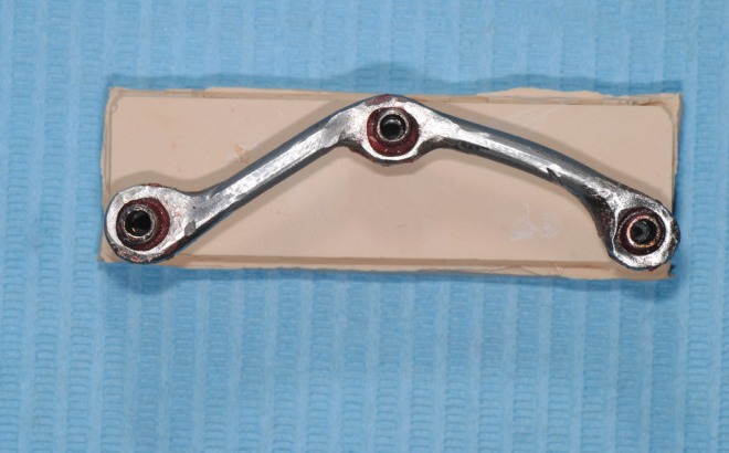
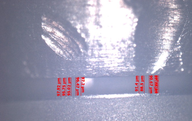
The abutments were tightened on the implant replicas and the metal framework was placed on the abutments and they were connected with PMMA resin (Pattern Resin LS, GC America Inc) using the bead brush technique, (Fig. 3). Twenty minutes after, the abutment screws were untightened and the abutment/framework complex was transferred to the POM block (83,97). Abutment screw no.1 was then tightened with a torque of 20N and the gap between the prosthetic platforms of implants no.2 and 3 and the corresponding abutments was measured using a special software (Axiovision, Carl Zeiss) and a camera (Axiocam ICc 1, Carl Zeiss) mounted on an optical microscope (Axioskop 40, Carl Zeiss) (29,98). A new screw was used every time. All measurements were made under a 10× magnification. The gap was measured by taking 10 measurements, 5 on each side of the center of the prosthetic platform (99). This method was employed since measurements could not be made towards the ends of the prosthetic platform due to its convexity and the blurriness of the image (80), (Figs. 4,5).
Figure 3.
Cast implant-supported bar connected with PMMA resin.
Figure 4.
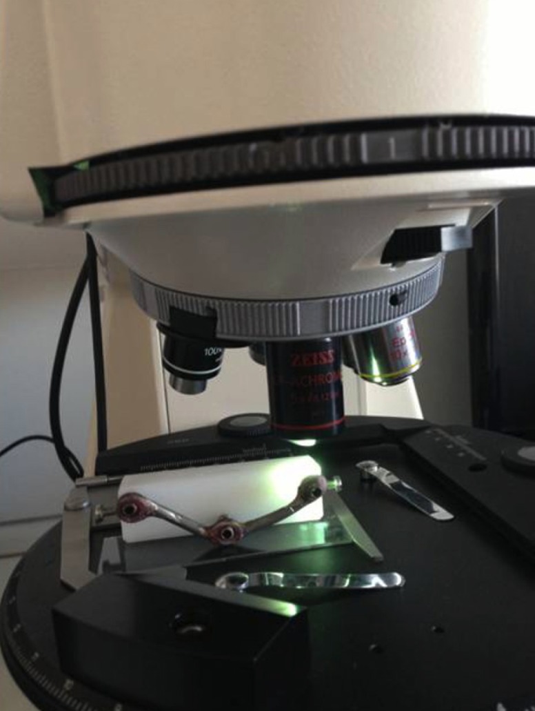
Optical microscope used for the measurements.
Figure 5.
Marginal discrepancy as recorded by the special software used.
Twelve definitive casts were fabricated for each gypsum product. Forty measurements were performed for each cast: 10 measurements for each one of the abutments 1 and 3, and 20 for abutment 2. Therefore, 480 measurements were made for each dental stone, all by the same operator.
Room temperature (21±1oC) and relative humidity (50±10%) were recorded each day throughout the experiments, while a digital timer was used to standardize each procedure’s exact duration.
Mean, minimum, and maximum values were calculated. The Shapiro-Wilk test of normality was performed. Since the assumption of normality was not satisfied for all the measurements, Kruskal Wallis and Mann-Whitney non-parametric tests were used for the comparison of the different dental stones and the statistical analysis of the measurements. The coding used for the measurements is depicted in Table 2.
Table 2. Coding used for the measurements.
Results
Mean, minimum and maximum values (μm) for marginal discrepancies as related to various gypsum products and different screws fastened are summarized in Table 3, Table 4.
Table 3. Mean, minimum, and maximum values (μm) for Screw1_Abut2 marginal discrepancies.
Table 4. Mean, minimum, and maximum values (μm) for Screw1_Abut3 marginal discrepancies.
The non-parametric Kruskal-Wallis test revealed a statistically significant effect of the stone factor on the marginal discrepancy for all Sheffield test combinations: 1. Abutment 2 when screw was fastened on abutment 1 (χ2=3, df=35.33, P<0.01), 2. Abutment 3 when the screw was fastened on abutment 1 (χ2=3, df=37.74, P<0.01), 3. Abutment 1 when the screw was fastened on abutment 3 (χ2=3, df=39.79, P<0.01), 4. Abutment 2 when the screw was fastened on abutment 3 (χ2=3, df=37.26, P<0.01), ( Table 5, Table 6).
Table 5. Mean, minimum and maximum values (μm) for Screw3_Abut1 marginal discrepancies.
Table 6. Mean, minimum, and maximum values (μm) for Screw3_Abut2 marginal discrepancies.
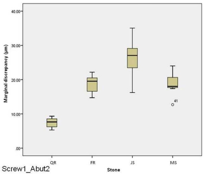
For abutment 2, when the screw was fastened on abutment 1, the smallest marginal opening was noted for QuickRock (QR) with a mean value of 7.38μm, and the biggest was for Jade Stone (JS) with a mean value of 26.35μm ( Table 3). Box plots of marginal discrepancies for different gypsum products are shown in Fig. 6. The Mann-Whitney test (P<.06) was then used to test significant differences among the different stones, in sets of two ( Table 7, Table 8). Marginal discrepancies noted on abutment 2, when FujiRock (FR) and Moldasynt (MS) were used, were not statistically significant.
Figure 6.
Box plots of the marginal discrepancy for abutment 2, when the screw was fastened on abutment 1.
Table 7. Kruskal-Wallis one-way analysis of variance.
Table 8. Mann-Whitney test (P<.05) for Screw1_Abut2 marginal discrepancies (μm) for different dental stones (N=12) (α=.05).
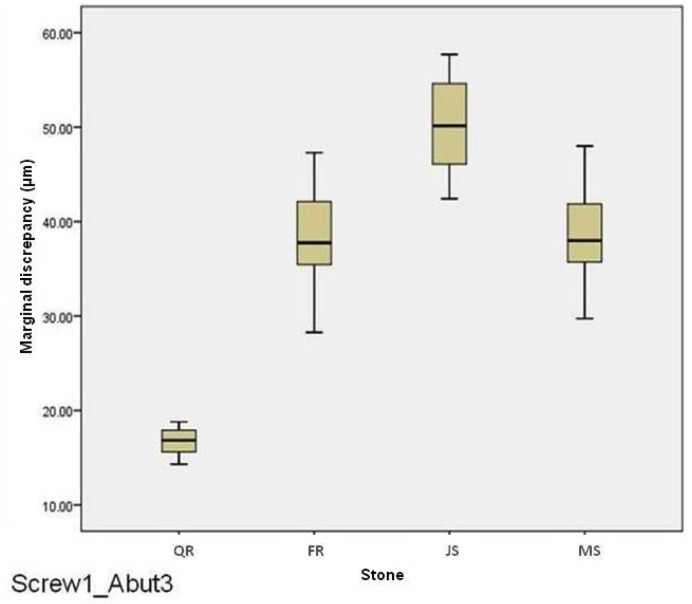
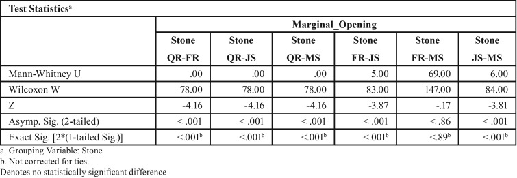
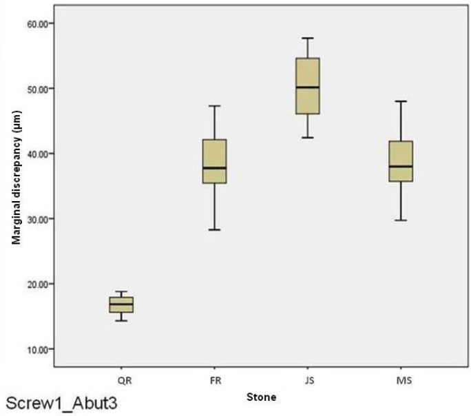
For abutment 3, when the screw was fastened on abutment 1, the smallest marginal opening was noted for QuickRock with a mean value of 16.72μm, and the biggest was for Jade Stone with a mean value of 50.30μm ( Table 4). Box plots of the marginal discrepancy illustrating the means and the standard deviations for different gypsum products are shown in Fig. 7. Mann-Whitney test (P<.06) was then used to test significant differences among the different stones, in sets of two ( Table 9). Marginal discrepancies noted on abutment 2, when FujiRock (FR) and Moldasynt (MS) were used, were not statistically significant.
Figure 7.
Box plots of the marginal discrepancy for abutment 3, when the screw was fastened on abutment 1.
Table 9. Mann-Whitney test for Screw1_Abut3 marginal discrepancies (μm) for different dental stones (N=12) (α=.05).
For abutment 1, when the screw was fastened on abutment 3, the smallest marginal opening was noted for Quick Rock with a mean value of 16.34 μm, and the biggest was for Jade Stone with a mean value of 48.43μm ( Table 5). Box plots of the marginal discrepancy illustrating the means and the standard deviations for different gypsum products are shown in Fig. 8. The Mann-Whitney test (P<.06) was then used to test significant differences among the different stones, in sets of two ( Table 10). Marginal discrepancies noted on abutment 2 were statistically significant for all dental stones.
Figure 8.
Box plots of the marginal discrepancy for abutment 1, when the screw was fastened on abutment 3.
Table 10. Mann-Whitney test for Screw3_Abut1 marginal discrepancies (μm) for different dental stones (N=12) (α=.05).
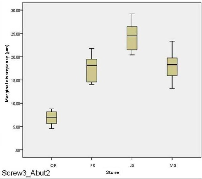
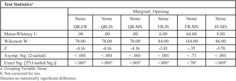
For abutment 2, when the screw was fastened on abutment 3, the smallest marginal opening was noted for Quick Rock with a mean value of 6.87μm, and the biggest was for Jade Stone with a mean value of 24.37μm ( Table 6). Box plots of the marginal discrepancy illustrating the means and the standard deviations for different gypsum products are shown in Fig. 9. The Mann-Whitney test (P<.06) was then used to test significant differences among the different stones, in sets of two ( Table 11). Marginal discrepancies noted on abutment 2 - when FujiRock (FR) and Moldasynt (MS) were used - were not statistically significant.
Figure 9.
Box plots of the marginal discrepancy for abutment 2, when the screw was fastened on abutment 3.
Table 11. Mann-Whitney test for Screw3_Abut2 marginal discrepancies (μm) for different dental stones (N=12) (α=.05).
Discussion
The study investigated the effect of dental stones on the accuracy of fitting of an implant supported screw-retained bar. The results of this study indicate that dental stones significantly affect the fitting of an implant supported screw-retained bar. Therefore, the null hypothesis was rejected.
Marginal adaptation between multiple abutments and implants’ prosthetic platforms is influenced by several factors including the impression material, impression techniques, dental stone used for the fabrication of the definitive models, wax properties, investment properties, investing procedures, alloy, casting and finishing procedures. The present study focused on only the gypsum products. Four commonly employed dental stones were used.
The results of the present study suggest that not all dental stones used for the fabrication of definitive casts provide an equally accurate fit of implant supported prostheses. It is evident that Quick Rock presents the best results, while Jade Stone the worst ones. Fujirock and Moldasynt, which are both type IV dental stones, did not differ significantly. These results were somewhat anticipated as Jade Stone is a type V dental stone, which is characterized as a high strength, high expansion stone.
The Sheffield test was adopted in this study, as it is widely clinically used (37,38). Moreover, the marginal discrepancy between the abutment and implant’s prosthetic platform was recorded and used as means of existence of passive fit or not. In that sense, none of the dental stones tested could provide a 100% passive fit, as marginal discrepancies ranged from 6.88μm to 50.31μm. The smaller marginal discrepancies were always noted at the middle implant. This is logical as the discrepancy is magnified as the distance becomes bigger (38).
As mentioned in the introduction, acceptable marginal discrepancies have ranged through the years, from 10 to 150 μm. In that manner, only Quick Rock was found to produce definitive casts which may provide fabrication of prostheses with marginal discrepancies close to the 10 μstrict standards that Brånemark, Romero et al. and Abduo and Lyons have set. This 10 μm standard could be achieved when the distance between two neighboring implants was 20 mm, but not when the distance was 56 mm. In that last case the marginal discrepancy was in the range of 16μm, which was less than the 26-30μm standard that Assif and Klineberg and Murray have set. Definitive casts made by type IV dental stones (FR and MS) produced marginal discrepancies which were smaller than the 26-30μm limit for the 20mm distance between the two implants, but not for the 56mm distance. The same applied for the type V dental stone. It should be mentioned however, that the prosthetic bars fabricated on the definitive casts produced by all gypsum products included in this study presented smaller marginal discrepancies than the 150μm limit set by Jemt in 1991 and Yanase in 1994 (10,37).
Marginal discrepancies below 20μm cannot be detected with either traditional x-ray films or digital periapical radiographs (49). Therefore, the 10μm acceptable marginal opening initially discussed by Brånemark cannot be perceived. Even, the 26-30μm acceptable marginal discrepancy limit falls very close to the detection capacity of the means available today.
The results of the present study agree with those of Wise (69), who found that definitive casts, on which implant supported fixed prostheses are fabricated, made by ultra-low expansion impression plaster are more accurate than casts made by conventional Type IV die stone. It should be mentioned however, that there are some differences both in the methodology and in the materials used between the study of Wise and the present study, with most profound the facts that Wise has used implant analogs instead of implants and fixed implant supported restorations made of impression plaster. On the contrary, in the present study a cast non-precious alloy framework connected to the abutments with a minimal amount of PMMA acrylic resin was employed. This was done in order to eliminate factors which could potentially influence the final outcome. These include wax distortion, investment expansion, alloy shrinkage and finishing procedures. Additionally, in the present study a mounting stone instead of an impression plaster has been used. It should be mentioned that Wise observed much bigger marginal discrepancies than the ones recorded in the present study. The use of casts instead of a rigid model to simulate the intraoral position of the implants, the expansion of the impression plaster indices which were used instead of a cast framework, the measurements that were made on projections of photographic slides and the use of laboratory analogs instead of implants may have contributed to the different numerical results.
The results of this study do not agree with those of Chang et al. (62) who concluded that the accuracy of the definitive casts is not influenced by the type of dental stone used. Nevertheless, there are some distinct differences between that study and the present one. First, Chang et al. investigated three impression techniques, two impression materials and two gypsum products, of which one was a type III and the other one a type IV. As already mentioned, the present study investigated only the influence of different gypsum products on the marginal discrepancy between the implant and the prosthesis. Second, the dimensional changes in that paper have been measured in the horizontal plane, while in the present one only the vertical discrepancy was measured.
Although every effort was made to standardize the multiple variables in the present study, some limitations were inevitably present. These included: a) the machining tolerance of the selected implant components (71-73), b) the fact that measurements were performed only in the vertical plane, c) the fact that mandibular flexure could not be taken into account, d) the temperature and dry environment where the impressions were made.
According to the results of the present study it may be preferable to use a mounting stone when fabricating prostheses supported by multiple implants, as this will decrease the marginal discrepancy between the implants’ prosthetic platforms and the corresponding abutments. However, if both implants and natural teeth have to be restored in the same arch, then the mounting stone cannot be used, since its Vickers hardness is 95MPa, and therefore a great risk of damage to the margins of the dies during the waxing procedures exists. In those cases a type IV dental stone should be employed. Another fact that should be taken into account is that type IV and type V dental stones provide sufficient working time, good detail reproduction and compatibility with elastomeric impression materials (60,61). On the other hand, mounting stones present a fast setting time, while their detail reproduction has not been investigated. Therefore the clinician has to weigh the advantages and disadvantages of using a mounting stone to fabricate a definitive cast.
Since no technique seems to be error-free, future studies should focus on comparing the use of dental stone products in combination with different impression materials and different implant components under simulated clinical conditions, taking also into account the operator variability. This methodology could provide valuable information and help the clinicians transfer laboratory findings to their everyday implant prosthodontics practice.
Conclusions
Within the limitations of this in vitro study the following conclusions can be drawn:
1. A significant correlation exists between marginal discrepancy and different dental gypsum products used for the fabrication of definitive casts for implant supported bars.
2. The smallest marginal discrepancy was noted on implant supported bars fabricated on definitive casts made by Type III mounting stone.
3. The biggest marginal discrepancy was noted on implant supported bars fabricated on definitive casts made by Type V dental stone.
4. The marginal discrepancies presented on implant supported bars fabricated on definitive casts made by two types of Type IV dental stone were not significantly different.
References
- 1.Adell R, Lekholm U, Rockler B, Brånemark P I. A 15-year study of osseointegrated implants in the treatment of the edentulous jaw. Int J Oral Surg. 1981;10:387–416. doi: 10.1016/s0300-9785(81)80077-4. [DOI] [PubMed] [Google Scholar]
- 2.Brånemark PI. Osseointegration and its experimental background. J Prosthet Dent. 1983;50:399–410. doi: 10.1016/s0022-3913(83)80101-2. [DOI] [PubMed] [Google Scholar]
- 3.Albrektsson T. A multicenter report on osseointegrated oral implants. J Prosthet Dent. 1988;60:75–84. doi: 10.1016/0022-3913(88)90355-1. [DOI] [PubMed] [Google Scholar]
- 4.Adell R, Ericksson B, Lekholm U, Brånemark PI, Jemt T. Long-term follow-up study of osseointegrated implants in the treatment of totally edentulous jaws. Int J Oral Maxillofac Implants. 1990;5:347–359. [PubMed] [Google Scholar]
- 5.Zarb GA, Schmitt A. The longitudinal clinical effectiveness of osseointegrated dental implants: the Toronto study. Part I: Surgical results. J Prosthet Dent. 1990;63:451–457. doi: 10.1016/0022-3913(90)90237-7. [DOI] [PubMed] [Google Scholar]
- 6.Zarb GA, Schmitt A. The longitudinal clinical effectiveness of osseointegrated dental implants: the Toronto study. Part II: The prosthetic results. J Prosthet Dent. 1990;64:53–61. doi: 10.1016/0022-3913(90)90153-4. [DOI] [PubMed] [Google Scholar]
- 7.Zarb GA, Schmitt A. The longitudinal clinical effectiveness of osseointegrated dental implants: the Toronto study. Part III: Problems and complications encountered. J Prosthet Dent. 1990;64:185–194. doi: 10.1016/0022-3913(90)90177-e. [DOI] [PubMed] [Google Scholar]
- 8.Priest G. Single-tooth implants and their role in preserving remaining teeth: a 10-year survival study. Int J Oral Maxillofac Implants. 1999;14:181–188. [PubMed] [Google Scholar]
- 9.Sones AD. Complications with osseointegrated implants. J Prosthet Dent. 1989;62:581–585. doi: 10.1016/0022-3913(89)90084-x. [DOI] [PubMed] [Google Scholar]
- 10.Jemt T. Failures and complications in 391 consecutively inserted fixed prostheses supported by Brånemark implants in the edentulous jaw: a study of treatment from the time of prostheses placement to the first annual check-up. Int J Oral Maxilofac Implants. 1991;6:270–276. [PubMed] [Google Scholar]
- 11.Rangert B, Gunne J, Sullivan DY. Mechanical aspects of a Brånemark implant connected to a natural tooth: an in vitro study. Int J Oral Maxillofac Implants. 1991;6:177–186. [PubMed] [Google Scholar]
- 12.Gunne J, Jemt T, Linden B. Implant treatment in partially edentulous patients: a report on prostheses after 3 years. Int J Prosthodont. 1994;7:143–148. [PubMed] [Google Scholar]
- 13.Kallus T, Bessing C. Loose gold screws frequently occur in full-arch fixed prostheses supported by osseontegrated implants after 5 years. Int J Oral Maxillofac Implants. 1994;9:169–178. [PubMed] [Google Scholar]
- 14.Byrne D, Houston F, Cleary R, Claffey N. The fit of cast and premachined implant abutments. J Prosthet Dent. 1998;80:184–192. doi: 10.1016/s0022-3913(98)70108-8. [DOI] [PubMed] [Google Scholar]
- 15.Binon PP. Implants and components: entering the new millennium. Int J Oral Maxillofac Implants. 2000;15:76–94. [PubMed] [Google Scholar]
- 16.Schwarz MS. Mechanical complications of dental implants. Clin Oral Implants Res. 2000;11(Suppl):156–158. doi: 10.1034/j.1600-0501.2000.011s1156.x. [DOI] [PubMed] [Google Scholar]
- 17.Nissan J, Gross M, Shifman A, Assif D. Stress levels for well-fitting implant superstructures as a function of tightening force levels, tightening sequence and different operators. J Prosthet Dent. 2001;86:20–23. doi: 10.1067/mpr.2001.115182. [DOI] [PubMed] [Google Scholar]
- 18.Sahin S, Cehreli MC. The significance of passive framework fit in implant prosthodontics: current status. Implant Dent. 2001;10:85–92. doi: 10.1097/00008505-200104000-00003. [DOI] [PubMed] [Google Scholar]
- 19.Al-Turki LE, Chai J, Lautenschlager EP, Hutten MC. Changes in prosthetic screw stability because of misfit of implant-supported prostheses. Int J Prosthodont. 2002;15:38–42. [PubMed] [Google Scholar]
- 20.Goodacre CJ, Bernal G, Rungcharassaeng K, Kan JYK. Clinical complications with implants and implant prostheses. J Prosthet Dent. 2003;90:121–132. doi: 10.1016/S0022-3913(03)00212-9. [DOI] [PubMed] [Google Scholar]
- 21.Johansson G, Palmqvist S. Complications, supplementary treatment and maintenance in edentulous arches with implant-supported fixed prostheses. Int J Prosthodont. 1990;3:89–92. [PubMed] [Google Scholar]
- 22.Carlson B, Carlsson GE. Prosthodontic complications in osseointegrated dental implant treatment. Int J Oral Maxillofac Implants. 1993;9:90–94. [PubMed] [Google Scholar]
- 23.Millington ND, Leung T. Inaccurate fit of implant superstructures. Part 1: stresses generated on the superstructure relative to the size of fit discrepancy. Int J Prosthodont. 1995;8:511–516. [PubMed] [Google Scholar]
- 24.Rangert B, Krogh PH, Langer B, Van Roekel N. Bending overload and implant fracture: a retrospective clinical analysis. Int J Oral Maxillofac Implants. 1995;10:326–334. [PubMed] [Google Scholar]
- 25.Skalak R. Biomechanical considerations in osseointegrated prostheses. J Prosthet Dent. 1983;49:843–848. doi: 10.1016/0022-3913(83)90361-x. [DOI] [PubMed] [Google Scholar]
- 26.Worthington P, Bolender CL, Taylor TD. The Swedish system of osseointegrated implants: problems and complications encountered during a 4-year trial period. Int J Oral Maxillofac Implants. 1987;2:77–84. [PubMed] [Google Scholar]
- 27.Frost HM. Vital biomechanics: proposed general concepts for skeletal adaptations to mechanical usage. Calcif Tissue Int. 1988;42:145–156. doi: 10.1007/BF02556327. [DOI] [PubMed] [Google Scholar]
- 28.Tolman DE, Laney WR. Tissue-integrated prosthesis complications. Int J Oral Maxillofac Implants. 1992;7:477–484. [PubMed] [Google Scholar]
- 29.Tan KB, Rubenstein JE, Nicholls JI, Yuodelis RA. Three-dimensional analysis of the casting accuracy of one-piece, osseointegrated implant-retained prostheses. Int J Prosthodont. 1993;6:346–363. [PubMed] [Google Scholar]
- 30.Jemt T, Lekholm U. Measurements of bone and framework deformations induced by misfit of implant superstructures. A pilot study in rabbits. Clin Oral Impl Res. 1998;9:272–280. doi: 10.1034/j.1600-0501.1998.090408.x. [DOI] [PubMed] [Google Scholar]
- 31.Duyck J, Ronold HJ, van Oosterwyck H, Naert I, Vander Sloten J, Ellingsen JE. The influence of static and dynamic loading on marginal bone reactions around osseointegrated implants: an animal experimental study. Clin Oral Impl Res. 2001;12:207–218. doi: 10.1034/j.1600-0501.2001.012003207.x. [DOI] [PubMed] [Google Scholar]
- 32.Gratton DG, Aquilino SA, Stanford CM. Micromotion and dynamic fatigue properties of the dental implant-abutment interface. J Prosthet Dent. 2001;85:47–52. doi: 10.1067/mpr.2001.112796. [DOI] [PubMed] [Google Scholar]
- 33.Hermann JS, Schoolfield JD, Schenk RK, Buser D, Cochran DL. Influence of the size of the microgap on crestal bone changes around titanium implants. A histometric evaluation of unloaded non-submerged implants in the canine mandible. J Periodontol. 2001;72:1372–1383. doi: 10.1902/jop.2001.72.10.1372. [DOI] [PubMed] [Google Scholar]
- 34.Melsen B, Lang NP. Biological reactions of alveolar bone to orthodontic loading of oral implants. Clin Oral Impl Res. 2001;12:144–152. doi: 10.1034/j.1600-0501.2001.012002144.x. [DOI] [PubMed] [Google Scholar]
- 35.King GN, Hermann JS, Schoolfield JD, Buser D, Cochran DL. Influence of the size of the microgap on crestal bone levels in non-submerged dental implants: A radiographic study in the canine mandible. J Periodontol. 2002;73:1111–1117. doi: 10.1902/jop.2002.73.10.1111. [DOI] [PubMed] [Google Scholar]
- 36.Spazzin AO, Dos Santos MB, Sobrinho LC, Consani RLX, Mesquita MF. Effects of horizontal misfit and bar framework material on the stress distribution of an overdenture-retaining bar system: a 3D finite element analysis. J Prosthodont. 2011;20:517–522. doi: 10.1111/j.1532-849X.2011.00759.x. [DOI] [PubMed] [Google Scholar]
- 37.Yanase RT, Binon PP, Jemt T, Gulbransen HJ, Parel S. How do you test a cast framework fit for a full-arch fixed implant supported prosthesis? Int J Oral Maxillofac Implants. 1994;9:469–474. [Google Scholar]
- 38.Kan JY, Rungcharassaeng K, Bohsali K, Goodacre CJ, Lang BR. Clinical methods for evaluating implant framework fit. J Prosthet Dent. 1999;81:7–13. doi: 10.1016/s0022-3913(99)70229-5. [DOI] [PubMed] [Google Scholar]
- 39.Romero GG, Engelmeier R, Powers JM, Canterbury AA. Accuracy of three corrective techniques for implant bar fabrication. J Prosthet Dent. 2000;84:602–607. doi: 10.1067/mpr.2000.111494. [DOI] [PubMed] [Google Scholar]
- 40.Abduo JA, Lyons KL. Effect of vertical misfit on strain within screw-retained implant titanium and zirconia frameworks. J Prosthodont Res. 2012;56:102–109. doi: 10.1016/j.jpor.2011.09.001. [DOI] [PubMed] [Google Scholar]
- 41.Klineberg IJ, Murray GM. Design of superdstructures for osseointegrated fixtures. Swed Dent J. 1985;Suppl 28:63–69. [PubMed] [Google Scholar]
- 42.Assif D, Fenton A, Zarb GA, Schmitt A. Accuracy of implant impression techniques: effect of splinting material. Int J Periodontics Restorative Dent. 1992;12:113–121. [PubMed] [Google Scholar]
- 43.Inturregui JA, Aquilino SA, Ryther JS, Lund PS. Evaluation of three impression techniques for osseointegrated oral implants. J Prosthet Dent. 1993;69:503–509. doi: 10.1016/0022-3913(93)90160-p. [DOI] [PubMed] [Google Scholar]
- 44.Jemt T. Three-dimensional distortion of gold-alloy castings and welded titanium frameworks: Measurement of precision of fit between completed implant prostheses and the master cast in routine edentulous situations. J Oral Rehabil. 1995;22:557–564. doi: 10.1111/j.1365-2842.1995.tb01049.x. [DOI] [PubMed] [Google Scholar]
- 45.Assif D, Marshak B, Schmitt A. Accuracy of implant impression techniques. Int J Oral Maxillofac Implants. 1996;11:216–222. [PubMed] [Google Scholar]
- 46.Karl M, Winter W, Taylor TD, Heckmann SM. In vitro study on passive fit in implant-supported 5-unit fixed partial dentures. Int J Oral Maxillofac Implants. 2004;19:30–37. [PubMed] [Google Scholar]
- 47.Wenz HJ, Reuter HU, Hertrampf K. Accuracy of impressions and casts using different implant impression techniques in a multi-implant system with an internal hex connection. Int J Oral Maxillofac Implants. 2008;23:39–47. [PubMed] [Google Scholar]
- 48.Taylor TD, Agar JR, Vogiatzi T. Implant prosthodontics: current perspective and future directions. Int J Oral Maxillofac Implants. 2000;15:66–75. [PubMed] [Google Scholar]
- 49.Farman AG, Farman TT. RVG-ui: a sensor to rival direct-exposure intra-oral x-ray film. Int J of Comput Dent. 1999;2:183–196. [PubMed] [Google Scholar]
- 50.Hsu CC, Millstein PL, Stein RS. A comparative analysis of the accuracy of implant transfer techniques. J Prosthet Dent. 1993;69:588–593. doi: 10.1016/0022-3913(93)90287-x. [DOI] [PubMed] [Google Scholar]
- 51.Vigolo P, Millstein PL. Evaluation of master cast techniques for multiple abutment implant prostheses. Int J Oral Maxillofac Implants. 1993;8:439–446. [PubMed] [Google Scholar]
- 52.McCartney JW, Pearson R. Segmental framework matrix: master cast verification, corrected cast guide, and analog transfer template for implant-supported prostheses. J Prosthet Dent. 1994;71:197–200. doi: 10.1016/0022-3913(94)90031-0. [DOI] [PubMed] [Google Scholar]
- 53.Jemt T. In vivo measurements of precision of fit involving implant-supported prostheses in the edentulous jaw. Int J Oral Maxillofac. 1996;11:151–158. [PubMed] [Google Scholar]
- 54.Wee AG, Cheng AC, Eskridge RN. Accuracy of 3 conceptually different die systems used for implant casts. J Prosthet Dent. 2002;87:23–29. doi: 10.1067/mpr.2002.121110. [DOI] [PubMed] [Google Scholar]
- 55.Nomura GT, Reisbick MH, Preston JD. An investigation of epoxy resin dies. J Prosthet Dent. 1980;44:45–50. doi: 10.1016/0022-3913(80)90045-1. [DOI] [PubMed] [Google Scholar]
- 56.Schwartz HB, Leupold RJ, Thompson VP. Linear dimensional accuracy of epoxy resin and stone dies. J Prosthet Dent. 1981;45:621–625. doi: 10.1016/0022-3913(81)90422-4. [DOI] [PubMed] [Google Scholar]
- 57.Bailey JH, Donovan TE, Preston JD. The dimensional accuracy of improved dental stone, silverplated, and epoxy resin die materials. J Prosthet Dent. 1988;59:307–310. doi: 10.1016/0022-3913(88)90178-3. [DOI] [PubMed] [Google Scholar]
- 58.Duke P, Moore BK, Haug SP, Andres CJ. Study of the physical properties of type IV gypsum, resin-containing, and epoxy die materials. J Prosthet Dent. 2000;83:466–473. doi: 10.1016/s0022-3913(00)70043-6. [DOI] [PubMed] [Google Scholar]
- 59.Schäffer H, Dumfahrt H, Gausch K. Distance alterations of dies in saggital direction in dependence of the die material. J Prosthet Dent. 1989;61:684–688. doi: 10.1016/s0022-3913(89)80042-3. [DOI] [PubMed] [Google Scholar]
- 60.Millstein PL. Determining the accuracy of gypsum casts made from type IV dental stone. J Oral Rehab. 1992;19:239–243. doi: 10.1111/j.1365-2842.1992.tb01098.x. [DOI] [PubMed] [Google Scholar]
- 61.Kenyon BJ, Hagge MS, Leknius C, Daniels WC, Weed ST. Dimensional accuracy of 7 die materials. J Prosthod. 2005;14:25–31. doi: 10.1111/j.1532-849X.2005.00007.x. [DOI] [PubMed] [Google Scholar]
- 62.Chang WG, Vahidi F, Bae KH, Lim BS. Accuracy of three implant impression techniques with different impression materials ans stones. Int J Prosthodont. 2012;25:44–47. [PubMed] [Google Scholar]
- 63.Peyton FA, Liebold JP, Ridgley GV. Surface hardness, compressive strength and abrasion resistance of indirect die stones. J Prosthet Dent. 1952;2:381–389. [Google Scholar]
- 64.Serrano JG, Lepe X, Townsend JD, Johnson GH, Thielke S. An accuracy evaluation of four removable die systems. J Prosthet Dent. 1998;80:575–580. doi: 10.1016/s0022-3913(98)70035-6. [DOI] [PubMed] [Google Scholar]
- 65.Finger W. Effect of the setting expansion of dental stone upon the die precision. Eur J Oral Sci. 1980;88:159–160. doi: 10.1111/j.1600-0722.1980.tb01208.x. [DOI] [PubMed] [Google Scholar]
- 66.Lautenschlager EP, Corbin F. Investigation on the expansion of dental stone. J Dent Res. 1969;48:206–210. doi: 10.1177/00220345690480020701. [DOI] [PubMed] [Google Scholar]
- 67.Winkler MM, Monaghan P, Gilbert JL, Lautenschlarger EP. Comparison of four techniques for monitoring the setting kinetics of gypsum. J Prosthet Dent. 1998;79:532–536. doi: 10.1016/s0022-3913(98)70174-x. [DOI] [PubMed] [Google Scholar]
- 68.Heshmati RH, Nagy WW, Wirth CG, Dhuru VB. Delayed linear expansion of improved dental stone. J Prosthet Dent. 2002;88:26–31. [PubMed] [Google Scholar]
- 69.Wise M. Fit of implant-supported fixed prostheses fabricated on master casts made from a dental stone and a dental plaster. J Prosthet Dent. 2001;86:532–538. doi: 10.1067/mpr.2001.119315. [DOI] [PubMed] [Google Scholar]
- 70.Wee AG, Schneider RL, Aquilino SA, Huff TL, Lindquist TJ, Williamson DL. Evaluation of the accuracy of solid implant casts. J Prosthod. 1998;7:161–169. doi: 10.1111/j.1532-849x.1998.tb00199.x. [DOI] [PubMed] [Google Scholar]
- 71.Binon PP. Implants and components: entering the new millennium. Int J Oral Maxillofac Implants. 2000;15:76–94. [PubMed] [Google Scholar]
- 72.Binon PP. Evaluation of machining accuracy and consistency of selected implants, standard abutments, and laboratory analogs. Int J Prosthodont. 1995;8:162–178. [PubMed] [Google Scholar]
- 73.Vigolo P, Fonzi F, Majzoub Z, Cordioli G. Evaluation of gold-machined UCLA-type abutments and CAD/CAM titanium abutments with hexagonal external connection and with internal connection. Int J Oral Maxillofac Implants. 2008;23:247–252. [PubMed] [Google Scholar]
- 74.Cehreli M, Duyck J, Cooman M, Puers R, Naert I. Implant design and interface force transfer. A photoelastic and strain-gaugeanalysis. Clin Oral Impl Res. 2004;15:249–257. doi: 10.1111/j.1600-0501.2004.00979.x. [DOI] [PubMed] [Google Scholar]
- 75.Cabral LM, Guedes CG. Comparative analysis of 4 impression techniques for implants. Implant Dent. 2007;16:187–194. doi: 10.1097/ID.0b013e3180587b3f. [DOI] [PubMed] [Google Scholar]
- 76.Goll GE. Production of accurately fitting full-arch implant frameworks: Part I – clinical procedures. J Prosthet Dent. 1991;66:377–384. doi: 10.1016/0022-3913(91)90266-y. [DOI] [PubMed] [Google Scholar]
- 77.Burawi G, Houston F, Byrne D, Claffey N. A comparison of the dimensional accuracy of the splinted and unsplinted impression techniques for the Bone-Lock implant system. J Prosthet Dent. 1997;77:68–75. doi: 10.1016/s0022-3913(97)70209-9. [DOI] [PubMed] [Google Scholar]
- 78.Inturregui JA, Aquilino SA, Ryther JS, Lund PS. Evaluation of three impression techniques for osseointegrated dental implants. J Prosthet Dent. 1993;69:503–509. doi: 10.1016/0022-3913(93)90160-p. [DOI] [PubMed] [Google Scholar]
- 79.Vigolo P, Majzoub Z, Cordioli G. In vitro comparison of master cast accuracy for single tooth implant replacement. J Prosthet Dent. 2000;83:562–566. doi: 10.1016/s0022-3913(00)70015-1. [DOI] [PubMed] [Google Scholar]
- 80.Del' Acqua MA, Arioli-Filho JN, Compagnoni MA, Mollo FA Jr. Accuracy of impression and pouring techniques for an implant supported prosthesis. Int J Oral Maxillofac Implants. 2008;23:226–236. [PubMed] [Google Scholar]
- 81.Del' Acqua MA, Chavez AM, Castanharo SM, Compagnoni MA, Mollo FA Jr. The effect of splint material rigidity in implant impression techniques. Int J Oral Maxillofac Implants. 2010;25:1153–1158. [PubMed] [Google Scholar]
- 82.Moon PC, Eshleman JR, Douglas HB Jr, Garrett SG. Comparison of accuracy of soldering indices for fixed prostheses. J Prosthet Dent. 1978;40:35–38. doi: 10.1016/0022-3913(78)90155-5. [DOI] [PubMed] [Google Scholar]
- 83.Mojon P, Oberholzer JP, Meyer JM, Belser UC. Polymerization shrinkage of index and pattern acrylic resins. J Prosthet Dent. 1990;64:684–688. doi: 10.1016/0022-3913(90)90296-o. [DOI] [PubMed] [Google Scholar]
- 84.Spector MR, Donovan TE, Nicholls JI. An evaluation of impression techniques for osseointegrated implants. J Prosthet Dent. 1990;63:444–447. doi: 10.1016/0022-3913(90)90235-5. [DOI] [PubMed] [Google Scholar]
- 85.Dumbrigue HB, Gurun DC, Javid NS. Prefabricated acrylic resin bars for splinting implant transfer copings. J Prosthet Dent. 2000;84:108–110. doi: 10.1067/mpr.2000.107914. [DOI] [PubMed] [Google Scholar]
- 86.Peregrina A, Land MF, Wandling C, Johnston WM. The effect of different adhesives on vinyl polysiloxane bond strength to two tray materials. J Prosthet Dent. 2005;94:209–213. doi: 10.1016/j.prosdent.2005.06.011. [DOI] [PubMed] [Google Scholar]
- 87.Davis GB, Moser JB, Brindsden GI. The bonding properties of elastomer tray adhesives. J Prosthet Dent. 1976;36:278–285. doi: 10.1016/0022-3913(76)90183-9. [DOI] [PubMed] [Google Scholar]
- 88.Samman JM, Fletcher AM. A study of impression tray adhesives. Quintessence Int. 1985;16:305–309. [PubMed] [Google Scholar]
- 89.Cho GC, Donovan TE, Chee WWL, White SN. Tensile bond strength of polyvinylsiloxane impression bonded to a custom tray as a function of drying time: Part I. J Prosthet Dent. 1995;73:419–423. doi: 10.1016/s0022-3913(05)80068-x. [DOI] [PubMed] [Google Scholar]
- 90.Payne JA, Pereira BP. Bond strength of two nonaqueous elastomeric impression materials bonded to two thermoplastic resin tray materials. J Prosthet Dent. 1995;74:563–568. doi: 10.1016/s0022-3913(05)80306-3. [DOI] [PubMed] [Google Scholar]
- 91.Petropoulos VC, Weintraub A, Weintraub GS. Predoctoral fixed prosthodontics curriculum survey. J Prosthodont. 1998;7:183–191. doi: 10.1111/j.1532-849x.1998.tb00202.x. [DOI] [PubMed] [Google Scholar]
- 92.Chee WW, Donovan TE. Polyvinyl siloxane impression materials: a review of properties and techniques. J Prosthet Dent. 1992;68:728–732. doi: 10.1016/0022-3913(92)90192-d. [DOI] [PubMed] [Google Scholar]
- 93.Lorenzoni M, Pertl C, Penker K, Polansky S, Sedaj B, Wegschneider WA. Comparison of the transfer precision of three different impression materials in combination with transfer caps for Frialit-2 system. J Oral Rehab. 2000;27:629–638. doi: 10.1046/j.1365-2842.2000.00594.x. [DOI] [PubMed] [Google Scholar]
- 94.Eames WB, Wallace SW, Suway NB, Rogers LB. Accuracy and dimensional stability of elastomeric impression materials. J Prosthet Dent. 1979;42:159–162. doi: 10.1016/0022-3913(79)90166-5. [DOI] [PubMed] [Google Scholar]
- 95.Boulton JL, Gage JP, Vincent PF, Basford KE. A laboratory study of dimensional changes for three elastomeric impression materials using custom and stock trays. Austr Dent J. 1996;41:398–404. doi: 10.1111/j.1834-7819.1996.tb06026.x. [DOI] [PubMed] [Google Scholar]
- 96.Wee AG. Comparison of impression materials for direct multi-implant impressions. J Prosthet Dent. 2000;83:323–331. doi: 10.1016/s0022-3913(00)70136-3. [DOI] [PubMed] [Google Scholar]
- 97.McDonnel T, Houston F, Byrne D, Gorman C, Claffey N. The effect of time lapse on the accuracy of two acrylic resins used to assemble an implant framework for soldering. J Prosthet Den. 2004;91:538–540. doi: 10.1016/s0022-3913(02)52728-1. [DOI] [PubMed] [Google Scholar]
- 98.Garine WN, Funkenbusch PD, Ercoli C, Wodenscheck J, Murphy WC. Measurement of the rotational misfit and implant-abutment gap of all-ceramic abutments. In J Oral maxillofac Implants. 2007;22:928–938. [PubMed] [Google Scholar]
- 99.Oyagüe RC, Turrion AS, Toledano M, Monticelli F, Osorio R. In vitro vertical misfit evaluation of cast frameworks for cement-retained implant-supported prostheses. J Dent. 2009;37:52–58. doi: 10.1016/j.jdent.2008.09.007. [DOI] [PubMed] [Google Scholar]


