

Abstract
Objective:
The use of miniature X-ray source in electronic brachytherapy is on the rise so there is an urgent need to acquire more knowledge on X-ray spectrum production and distribution by a dose. The aim of this research was to investigate the influence of target thickness and geometry at the source of miniature X-ray tube on tube output.
Method:
Five sources were simulated based on problems each with a specific geometric structure and conditions using MCNPX code. Tallies proportional to the output were used to calculate the results for the influence of source geometry on output.
Results:
The results of this work include the size of the optimal thickness of 5 miniature sources, energy spectrum of the sources per 50 kev and also the axial and transverse dose of simulated sources were calculated based on these thicknesses. The miniature source geometric was affected on the output x-ray tube.
Conclusion:
The result of this study demonstrates that hemispherical-conical, hemispherical and truncated-conical miniature sources were determined as the most suitable tools.
Keywords: Monte Carlo , Electronic Brachytherapy , Target Optimization , Energy Spectrum , Miniature Source
Introduction
Radioactive sources have been used up to the present time. Conventional brachytherapy has been well regarded because there are rapid dose reduction and normal tissues around target tumors which are protected. But the procedure requires that a patient is in contact with radioactive isotopes for a long time which can be dangerous [1]. Furthermore, there is a very high level of uncertainty in terms of intended dose distribution [2]. The use of more powerful energy (to achieve a wider penetration) extends the area exposed to a higher dose and thus increases the possibility of side effects [3]. The method of implant has a significant role in the success of common brachytherapy and the quality of the implant procedure in terms of it being a simple and well-tolerated method, as largely dependent on experience and expertise of the administrator [4]. The method has some limitations such as dose distribution and depth of each isotope [5]. Needs cannot be met using a radionuclide-based source [6].
A joint work between MIT University and a photoelectron company (led by Alan Siliski) in the 80s developed Electronic Brachytherapy System (eBS) as a new approach to avoid the aforementioned problems [7]. The advantages of eBS on radionuclide-based BT resources were as follows: radiation is produced by X-ray tube in eBS [8], and treatment dose can be adjusted by changing the X-ray tube voltage and current [9]. Administration of eBS does not require a highly protected environment [10]. Compared with the BT source isotopes, dose distribution and dose reduction percentage are more accurately controlled by adjusting the tube’s KVP [11] and this avoids giving an unnecessary dose to healthy tissue adjacent to the target tissue [12]. In eBT, a small water-cooled X-ray tube allows the radiation to be switched on or off [13]. Radiation quality in eBS can be changed in order to achieve a better consumption compliance by adjusting the tube potential [14]; eBT resources are more economic because they are activated only when needed [15]. Companies like Carl Zeiss (Oberkoche, Germany, INTRABEAM) [16,17] and Xoft (Fremont, Axxent C.A.) [18-20] and ELEKTA, (Stockholm, Sweden, Esteya) [21] have designed eBS systems to treat tumors. The eBS system was designed in 1996 by photoelectron company (INTRABEAM). It was one of the first in interstitial radio surgery [22]. In 2006, Rivard and his colleagues introduced a source model S700 as an electronic brachytherapy system [9]. The main factor of the system was its low energy use with high dose X-ray source [23]. Problems of the radioisotope brachytherapy system, on the one hand, and benefits of electronic brachytherapy systems based on existing references, on the other, are not reasons for the superiority of one method over the other, because each system has advantages and disadvantages. An important consideration is that unlike single or medium energy radioactive sources, the miniature x-ray tube (the heart of the system) in an electronic brachytherapy system has an energy spectrum that could be optimized with more research. In other words, the influence of geometrical structure of the tube in the production of X-ray needs further investigation, because the X-ray spectrum and the dose distribution in an electronic brachytherapy system are determined by the geometry of the source and structure of the target of eBS X-ray tube. The aim of this project was to evaluate the effect of the geometric structure of the source in the production of surface flux, the X-ray spectrum produced and the distribution of dosage of miniature X-ray source in electronic brachytherapy. This was investigated by tests on the effects of factors such as optimum target thickness, functional energy and the angle of target surface relative to electron beam.
Material and Methods
Simulation Tool
MCNPX is a computer code written in fortran90 for Monte Carlo simulation of radiation transport [24]. The base of MCNPX is MCNP which is the basic Monte Carlo code used for the transport of neutrons, photons and electrons or pairs of photons, electrons and neutrons [25]. MCNPX is now widely used as a radiation transport code [26]. It not only provides all the functionality of MCNP4C and MCNP5, it simulates the transport of 34 new types of particles such as protons and ions, and thus provides a wide range of energy particles [27]. MCNPX has advantages such as an ability to use enhanced electron physics, a powerful geometry package that allows modelling of different geometries, it is a robust system for extensive statistical review, offers numerous choices of changeable tallies, and is able to use numerous enhanced variance reduction techniques [28]. MCNPX can be used to simulate the electron-photon transport through target material considering the production of electrons from photons and vice versa [29]. In this study, MCNPX version (2.6.0) was used to assess the geometrical structure and thickness of the target, and to calculate the dose and the resultant X-ray photon spectrum.
Specifications of Simulated Sources
MCNPX (2.6.0) code was utilized to simulate 5 miniature X-ray sources based on their geometric structure applied in the simulations; these are shown in Figure 1. Densities of tungsten, beryllium and water with values of 19.3, 1.848 and 0.998 grams per cubic centimeter according to the reference [30] source were used in the simulation. Considering the need for the production of bremsstrahlung, at all stages of implementation, the code to transport the paired electron/photon MODE: P E was used. 1kev cutoff energy of photons and electrons in all parts of the simulation and calculation of dose and energy spectrum was used. According to that citation in reference [31], a DBCN card was developed to debug and other low-level controls of the code including a series of options that affect the general and physical performance of the particle transport process, so DBCN 17 j1 card used in this simulation is presented in the card data. Completing the input file in accordance with manual [32] a DBCN card was developed to debug and other low-level controls of the code including a series of options that affect the general and physical performance of the particle transport process, so DBCN 17 j1 card used in this simulation is presented in the card data. Completing the input file in accordance with manual [32] Cards Plib = 04P and elib = 03e were used. Materials such as tungsten, molybdenum and rhodium are suitable candidates for the production of X-rays as targets on the basis of atomic number and density. But tungsten was chosen as the target in this project for properties such as high atomic number and high melting point (3422C)[33]. These properties were considered important for producing efficient x-rays and bearing high strength sediment [34]. Since X-ray efficiency increases with the square of the atomic number (Z2), Tungsten is a good choice with Z = 79 [35]. It has the power, flexibility and low evaporation rate in a vacuum [36].
Figure1.
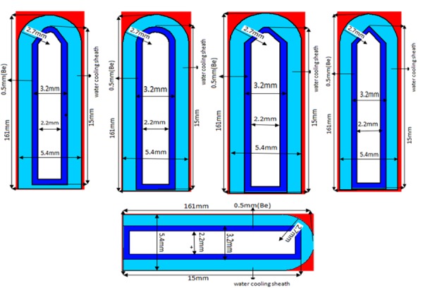
A view of miniature X-ray sources simulated for conducting the study
Reference [37] explains the PHYS card was used in MCNPX to determine the energy limitations in approximating physics and other parameters used for physical improvements in particle transportation. Based on this explanation, the electron-photon physics card was used, and in the specification of an electron source in the Data card provided, 1kev more than the amount of energy photons was defined as the highest energy. For example, if the electron source energy was considered 50 kev, then the highest-energy in the electron-photon physics card was selected as 51kev to avoid confusion in the calculations. In calculating the spectra and range of dosage, considerations were as follows: output window material (substrates) of beryllium with a thickness of 0.5 mm, due to advantages such as transparency to shorter X-ray wavelengths, availability, high thermal capacity and high strength to weight ratio [38], low atomic number and X-ray transport without absorption even at low energies [39]. At all stages of simulation, the sources were placed in spherical phantom, and the density of water or air can be selected depending on the type of output. The source active center (the place of bremsstrahlung) was placed on the origin and the origin was placed at the center of the sphere. For the production of bremsstrahlung, electrons bombed the target surface from a distance of 10 mm in various thicknesses.
Determination of Optimum Thickness of Target based on the Penetration of Impacting Electrons
Firstly, miniature sources with thicknesses of 0.01, 0.05, 0.1, 0.5, 1, 1.5, 2, 2.5, 3, 4, 5 and 6 microns with energies 20, 30, 40 and 50 kev were radiated through MCNPX Visual Editor Software with an electron beam particle display without the use of tallies. By reducing the penetration of the electron (electron range) into the target thickness and plot particle tracks, it was revealed that thicknesses of 0.01 and 0.05 microns were not considered appropriate because most of the electrons passed (Figure 2-a) higher than 3 microns due to the return of a majority of electrons (Figure 2-b); these thicknesses were therefore excluded.
Figure2.
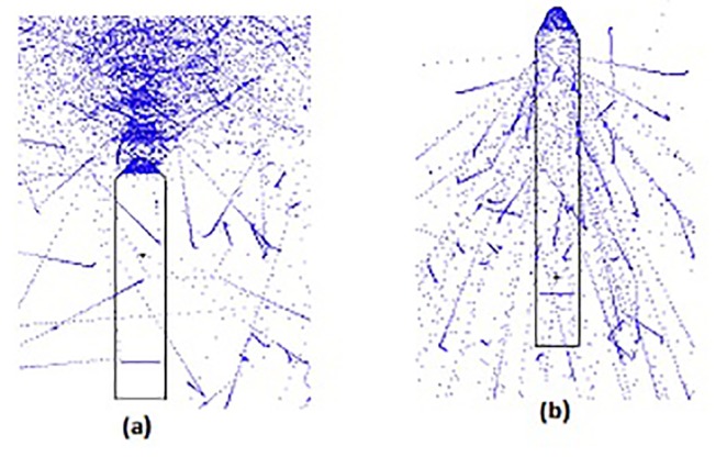
A view of the targets that had a size range of optimum thickness of sources
30 thicknesses of 0.1, 0.2, 0.3, 0.4, 0.5, ... and 3 microns with 0.1 microns increased with energies of 20, 30, 40 and 50 kev and single energy electron solid disc source with a radius of 0.8 mm were evaluated according to [10] over 600, 300-minute programs for 5 miniature sources (Figure 1), with 6 runs, at any point due to sequential cores, by computer specifications of Intel (R) core ™ I 7 - 4790k CPU@4.00GHz 4.00GHz, Ram 16.0 GB. Two surfaces of front (input) and opposite (output) were considered for the examined targets. The area where electrons collided was the input area and the area at which bremsstrahlung was formed was the output area. F2 tally for the incidents of electron contact with the target was used for the input area and on the output area, *F1 tally was used for the penetration of electrons. As a result, each of the energy levels used in miniature sources determined optimum thickness of the source.
Determination of Optimum Thickness of the Target using Computational Dose
At this stage, for each miniature source, 30 thicknesses of the previous section were used for the sources in Figure 1. 10 spherical detectors were used to measure the dose at 10 points considered on the central axis. The first detector was set at a distance of 0.5 cm from the active center of the source and the rest of the detectors, with an increase of 0.5 cm continued to 5 cm from the center of the source (Figure 3). F6 tally was used to calculate dose because of its high speed. For the implementation of each run (600, 300-minute runs), the average dose of 10 detectors was calculated and selected as the dose associated with that thickness, and the relative dose was used for plotting graphs. This procedure was carried out for each energy level and thickness; results not only confirmed the first method but also showed that it was very accurate.
Figure3.

A view of the form used to determine the optimum thickness by measuring the dose
Determination and Setting the Target Angle in Conical Sources
Considering the size of conical and truncated-conical sources shown in Figure 1; the first step was to set the cone apex angle at 90 degrees. The hemispherical-conical source target had a hemisphere radius of 0.5 mm cutting the cone, and its angle was obtained through calculation. In section of dose calculations, the optimum thickness, which produced the highest dose, created the angle that was considered as the optimum target angle and its amount for 4 energies used was roughly equal to 36 degrees; the results demonstrated that the radius of the hemisphere was effective.
Calculations of Energy Spectrum
Considering that the optimum thickness of the miniature sources was determined in the previous stages, among them only thicknesses of 1.3, 1.7, 1.3, 1.5 and 1.7 microns were chosen for conical-hemispherical, conical, hemispherical, planer and truncated-conical forms, respectively. The ring detector tally was a point detector tally where the place of tally of the detector was not a fixed point, but could be sampled in some places on the ring. A ring detector usually increases the efficiency of a point detector for problems related to geometric structures which are in symmetrical rotation around the axis [40]. According to this explanation, for calculating the spectra of ring tally F5 for this miniature sources, long axis symmetry was determined as the most preferable. To indicate the X-ray peak energy, bin cards with a 0.1kev step were used. By applying these conditions, the energy spectrum of source at distances of 2.5, 10 and 50 cm from active center of the source was calculated during the run time of 3700 minutes. The average statistical error was 4%.
Calculations of Dose
According to the MCNPX (2.6.0) manual, the dose is usually calculated using F6, *F4, and *F8 tallies. The use of either of these tallies to calculate the absorbed dose, has advantages and disadvantages, but according to these reasons, at low energy photon (less than 200KeV), an extensive range of secondary electrons in solid or liquid environments is usually insignificant [41]. Radiation loss is negligible [42]; this means that total kerma can be considered as the collision kerma [41]. This allows the collision kerma to be used as the absorbed dose [42]. The F6 tally was used to calculate the absorbed dose. Doses obtained from miniature sources on the transverse axis and the longitudinal axis at the distance of 0.5 to 2.4 cm from the center of the source’s active center with spherical detectors with a radius of 0.5 mm were calculated. The running time of each program was 2500 minutes and statistical error was between 1.5% and 3.5%.
Results
Table 1 and Figure 4 , 5 and 6 show the optimum size of the thickness of the targets for 5 sources called hemispherical-conical, truncated-conical, hemispherical and conical planer for energies 20, 30, 40 and 50 kev for which these optimal thicknesses in each target are a function of energy and shape of the target.
Table 1.
Optimum thicknesses obtained according to Figures 4, 5, and comparisons with other available references
| Energy | 20Kev | 30Kev | 40Kev | 50Kev |
|---|---|---|---|---|
| H-C a | 0.3 | 0.6 | 0.9 | 1.1 |
| Cb | 0.5 | 0.8 | 1.2 | 1.7 |
| Hc | 0.4 | 0.6 | 1.1 | 1.3 |
| T-Cd | 0.5 | 0.8 | 1.2 | 1.7 |
| Pe | 0.4 | 0.6 | 1.1 | 1.5 |
| Khajehf and etal 2015 | - | 0.65 | 0.85 | 1.45 |
| Safigholig and etal 2012 | 0.18 | 0.64 | 1.1 | 1.56 |
Optimal Thickness (µm) for a. Hemispherical -conical, b.conical, c.Hemispherical, d.Truncated -conical, e. Planer, f, g)
Figure4.
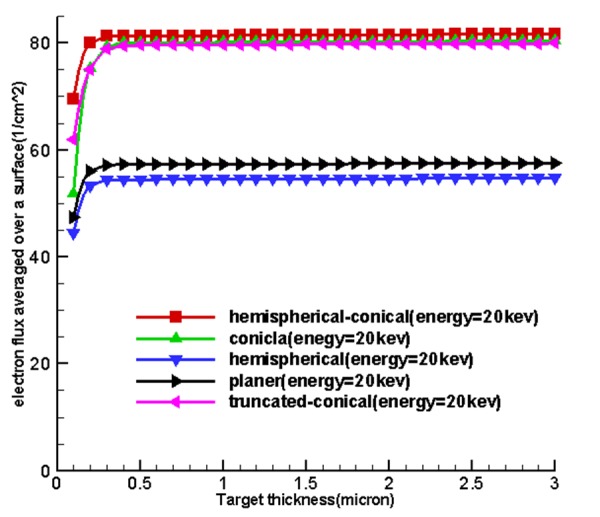
Diagrams obtained based on electron penetration , that show optimized thickness for the sources (first method)
Figure4.
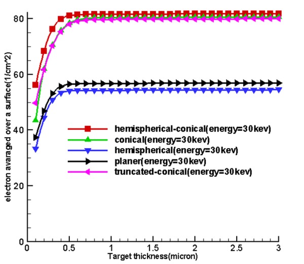
Figure4.
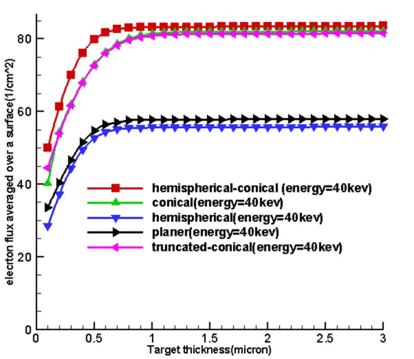
Figure4.
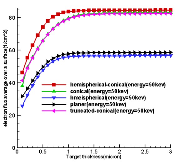
Figure5.
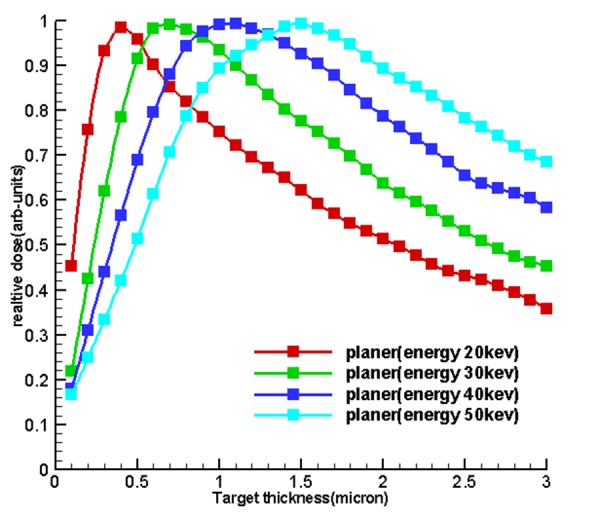
Diagrams of relative dose of the results of section of dose calculations to determine the optimum thickness and to validate the first
Figure5.
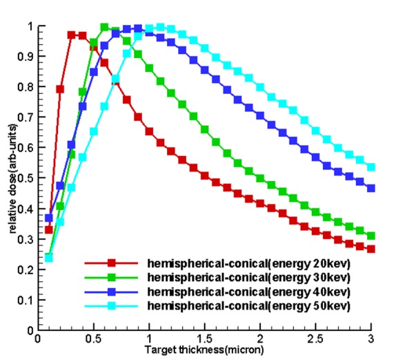
Figure5.
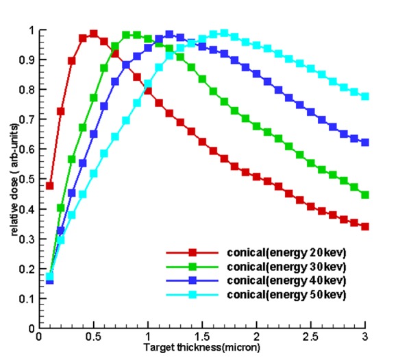
Figure5.
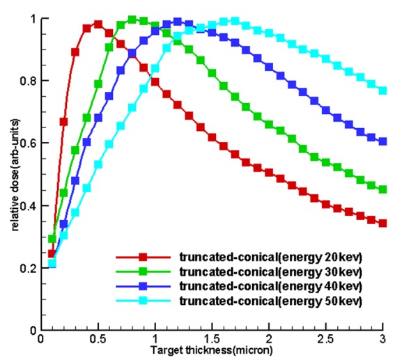
Figure5.
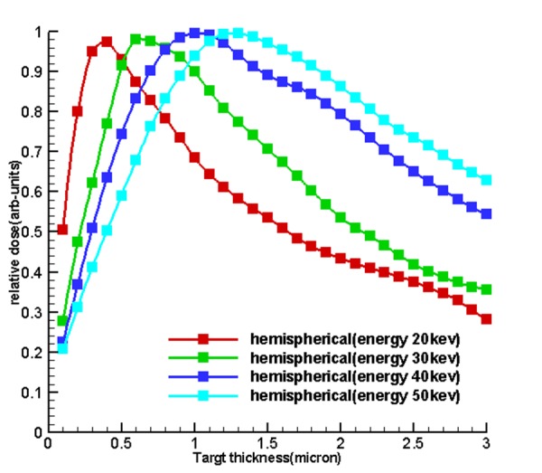
Figure6.
the diagram of the relationship between electron range with the release of energy within the target until it is stopped so that, the optimum thickness is less than the electron ranges and sources with larger optimum thickness, the electron range within them is far greater than the other sources
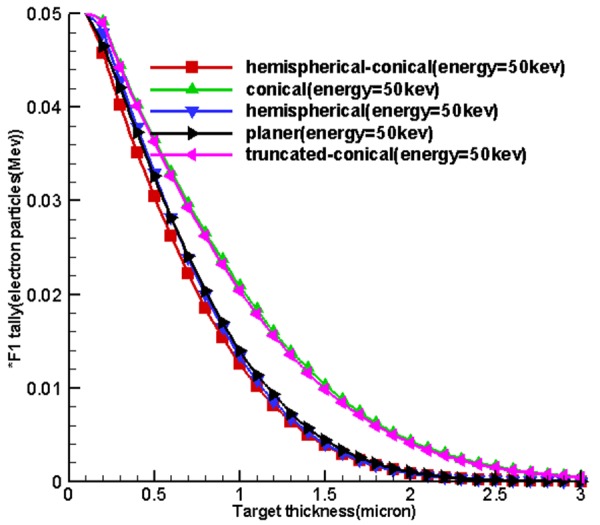
Figure 7 shows the energy spectrum of 5 sources called hemispherical-conical, truncated-conical, hemispherical and conical planer at the distances of 2.5, 10 and 50 cm from the active center of the sources. With the use of diagrams, it can be found that the shape of targets, the energy used affect the output spectrum, and the area under the curve (AUC) for any source is different and also, along with being away from the active center of the sources, according to the inverse square law, the intensity of the x-ray spectrum is reduced.
Figure7.
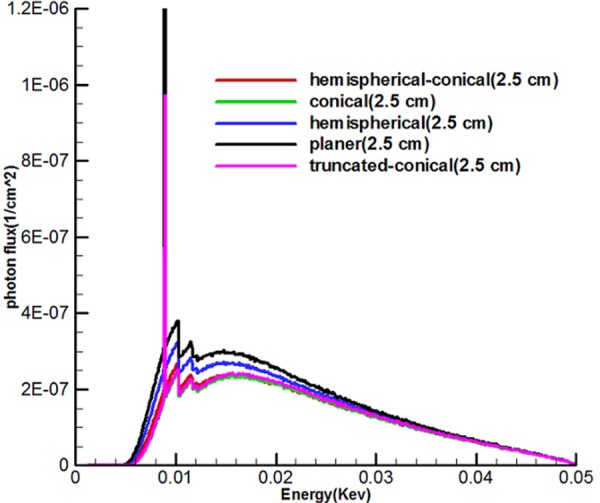
Shows spectra of 5 miniature X-ray source and suggests that the intensity of the planer source was higher than the rest and that the spectrum intensity declined sharply according to the increased distance from the source
Figure7.
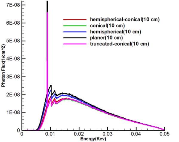
Figure7.
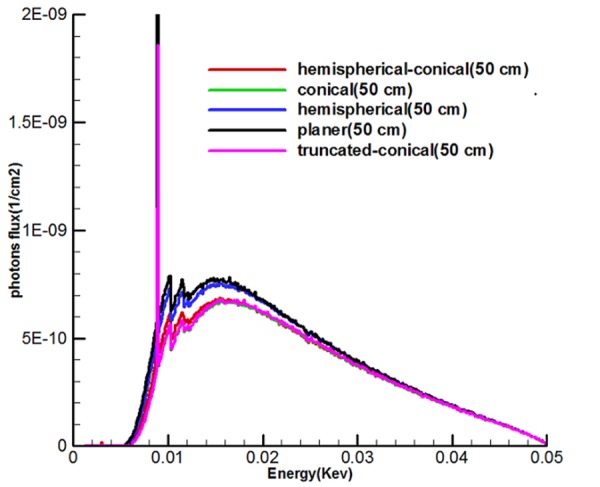
Figure 8 shows the effect of the shape of the target and energy used on the output (calculated dose of the transverse and longitudinal axes) 5 sources called the hemispherical-conical, truncated-conical, hemispherical and conical planer. These diagrams indicate that the planet, hemispherical sources have a higher axial dose than the family cone-shaped sources, and similarly the cone-shaped sources have the transverse doses higher than hemispherical, planer.
Figure8.
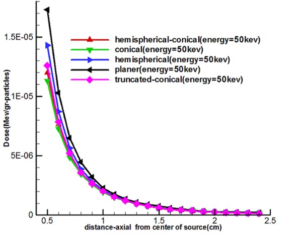
Comparison of axial and transverse dose distribution of a miniature X-ray source
Figure8.
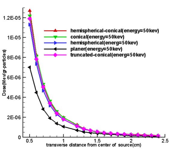
Figure 6 shows the diagram of the relationship between electron range with the release of energy within the target until it is stopped so that, the optimum thickness is less than the electron ranges and sources with larger optimum thickness, the electron range within them is far greater than other sources.
Discussion
Analysis of the Effect of Optimum Thickness in X-ray Production
The results of sections 2.4, 2.5 and 2.6 after running all the necessary items led to determination of optimum thickness of miniature source according to Table 1. In the functional miniature X-ray source in an electronic brachytherapy system, the transitional target used a thin conductive metal layer placed on the X-ray output window. When electrons collide with targets of a specific energy, the thickness that is placed in front of these electrons undergoes change. According to [43] if a target is too thin, then the source electrons pass relatively easily and generate relatively few bremsstrahlung X-ray photons. If the target is too thick, then photons created in the first part of the matter are weakened by the remaining matter. So, for any particular material, there is an optimum thickness that maximizes the dose on the axis from a converted target. It can be argued that at less the optimum thickness, then the photon intensity will pass the target and the average spectrum energy will decrease; at the optimum thickness the intensity of photons is the maximum and at greater thickness, intensity of photons will be less and average energy will decrease. Another justification in this regard is the electron range that based on reference [44] and Figure 6 in this study, it can be concluded that the optimum thickness of the target is less than that of the maximum range of electrons, because by increasing the thickness of the tungsten target, the probability of electron capture not only increases, but also the probability of self-absorption of the produced photons in the target increases. However, for a greater probability of energy self-absorption, it is gradually changing and the optimum thickness of the tungsten moves towards a higher value.
Analysis of the Effect of Target Shape on the Output of Sources
Figure 4 shows the curves obtained from the use of tally F2. Firstly, by increasing the thickness of the target matter, the average surface flux of electrons for the input target surface at the source increases until these quantities reach their maximum values at a specified thickness and at an increased thickness, then, the average surface flux of electrons and the number of electrons to pass is associated with an input surface which remains constant. Based on existing charts in Figure 4, considering the fact that the situation was the same for the miniature sources, the cone-shaped sources were placed higher and the miniature hemispherical-conical source was better at generating surface flux at all energy levels and in the first place and non-conical sources allocated the next places to themselves. This shows that the shape of the miniature source had a very important impact on the X-ray production, and the reason for using hemispherical-conical by Xoft Company can be the listed under the conditions because it had an appropriate structure for treatment and placing within the applicators.
Analysis of Calculated X-ray Spectrum
Figure 7 shows the continuous spectrum of bremsstrahlung generated by electron bombardment with an optimal target area for five miniature sources. It should be noted that unlike bremsstrahlung beams, specified X-rays emit discontinuous energy so that these figures indicate peaks on the transition spectrum of electrons from a higher layer to layer L. Since the continuous spectrum of tungsten has characteristic peaks with specific energy, characteristic peaks of these spectra show energies of 8.9, 10.2 and 11.5 kev which are related to layer L, because the energy used to bombard the target was 50kev. Spectra show that the area under the curve (intensity) of the planer source was higher than the rest. It can be argued that there must be a rational relationship between the area of the target and photons produced in the forward direction. As a result, while the production of average surface flux of electrons and number of electrons to pass through the hemispherical-conical source (Figure 4) were higher, in this case the non-conical surfaces had higher values in the direction of the source axis (the axis z) in the spectrum diagram, and this indicates that the shape of the source had a major role.
Investigation of Calculated Doses
For observing the effect of a miniature source on computational doses in this part of the study, doses calculated in longitudinal and transverse axes are shown in Figure 8. Hemispherical-conical-shaped sources had a higher dose along with the transverse axis compared to other miniature sources, and it suggests that dose of this source had more of a transverse field compared to other sources. The hemispherical-conical source had the highest surface-to-volume ratio compared to other sources. This has an important role in heat transfer and self-absorption; it is an advantage of this source compared to other sources and makes the dose higher closer to the source. Planer source generated a higher dose than other sources along the longitudinal axis and this is verifiable through spectra shown in Figure 4 and Figure 8. So, it can be said that the conical and modified sources were better in a transverse direction.
Conclusion
The results of the study revealed that not only the energy was impressive on the output of these sources, but the geometric structure of these sources clearly affected output. From among these miniature sources, hemispherical-conical, hemispherical and truncated-conical sources had more suitable structures for use in electronic brachytherapy.
Acknowledgement
This paper describes part of the results of research that was performed for the Ph.D. degree in field of medical physics (Thesis no. U-94148).The author would like to thank Dr. Stephen D. Davis (McGill University) for his helpful responses to questions asked about the subject of the study.
Conflict of Interest: None.
References
- 1.Cho SO, Heo SH. Super miniature X-ray tube using NANO material field emitter. United States: Google Patents; 2012. [Google Scholar]
- 2.Choe KS, Liauw SL. Radiotherapeutic strategies in the management of low-risk prostate cancer. ScientificWorldJournal. 2010;10:1854–69. doi: 10.1100/tsw.2010.179. [DOI] [PMC free article] [PubMed] [Google Scholar]
- 3.Porter AT, Blasko JC, Grimm PD, Reddy SM, Ragde H. Brachytherapy for prostate cancer. CA Cancer J Clin. 1995;45:165–78. doi: 10.3322/canjclin.45.3.165. [DOI] [PubMed] [Google Scholar]
- 4.Kubo HD, Glasgow GP, Pethel TD, Thomadsen BR, Williamson JF. High dose-rate brachytherapy treatment delivery: report of the AAPM Radiation Therapy Committee Task Group No. 59. Med Phys. 1998;25:375–403. doi: 10.1118/1.598232. [DOI] [PubMed] [Google Scholar]
- 5.Gierga DP, Shefer RE. Characterization of a soft X-ray source for intravascular radiation therapy. Int J Radiat Oncol Biol Phys. 2001;49:847–56. doi: 10.1016/S0360-3016(00)01510-8. [DOI] [PubMed] [Google Scholar]
- 6.Heoa S, Haa J, Choa S. An Optimization of Super-Miniature X-ray Target. 2011. [Google Scholar]
- 7.Dinsmore M, Harte KJ, Sliski AP, Smith DO, Nomikos PM, Dalterio MJ, et al. A new miniature x-ray source for interstitial radiosurgery: device description. Med Phys. 1996;23:45–52. doi: 10.1118/1.597790. [DOI] [PubMed] [Google Scholar]
- 8.Ihsan A, Heo SH, Kim HJ, Kang CM, Cho SO. An optimal design of X-ray target for uniform X-ray emission from an electronic brachytherapy system. Nuclear Instruments and Methods in Physics Research Section B: Beam Interactions with Materials and Atoms. 2011;269:1053–7. doi: 10.1016/j.nimb.2011.03.001. [DOI] [Google Scholar]
- 9.Rivard MJ, Davis SD, DeWerd LA, Rusch TW, Axelrod S. Calculated and measured brachytherapy dosimetry parameters in water for the Xoft Axxent X-Ray Source: an electronic brachytherapy source. Med Phys. 2006;33:4020–32. doi: 10.1118/1.2357021. [DOI] [PubMed] [Google Scholar]
- 10.Rivard MJ, Rusch TW, Axelrod S. Radiological dependence of electronic brachytherapy simulation on input parameters. Medical Physics. 2006:11747–4502. doi: 10.1118/1.2357021. [DOI] [PubMed] [Google Scholar]
- 11.Silvern D, Rusch T, Zaider M, editors Dosimetric Benefits of an Adjustable-Energy Electronic Brachytherapy Source. Medical Physics. 2004;31:1880. [Google Scholar]
- 12.Hiatt JR, Davis SD, Rivard MJ. A revised dosimetric characterization of the model S700 electronic brachytherapy source containing an anode-centering plastic insert and other components not included in the 2006 model. Med Phys. 2015;42:2764–76. doi: 10.1118/1.4919280. [DOI] [PubMed] [Google Scholar]
- 13.Rong Y, Welsh JS. New technology in high-dose-rate brachytherapy with surface applicators for non-melanoma skin cancer treatment: electronic miniature x-ray brachytherapy. Skin Cancer Overview: InTech; 2011. [Google Scholar]
- 14.Liu DMC. Characterization of novel electronic brachytherapy system. Montreal: McGill University; 2007. [Google Scholar]
- 15.Holt RW, Rivard MJ. Electronic brachytherapy: comparisons with external-beam and high-dose-rate 192Ir brachytherapy. J Am Coll Radiol. 2008;5:221–3. doi: 10.1016/j.jacr.2007.12.001. [DOI] [PubMed] [Google Scholar]
- 16.Clausen S, Schneider F, Jahnke L, Fleckenstein J, Hesser J, Glatting G, et al. A Monte Carlo based source model for dose calculation of endovaginal TARGIT brachytherapy with INTRABEAM and a cylindrical applicator. Z Med Phys. 2012;22:197–204. doi: 10.1016/j.zemedi.2012.06.003. [DOI] [PubMed] [Google Scholar]
- 17.Grobmyer SR, Lightsey JL, Bryant CM, Shaw C, Yeung A, Bhandare N, et al. Low-kilovoltage, single-dose intraoperative radiation therapy for breast cancer: results and impact on a multidisciplinary breast cancer program. J Am Coll Surg. 2013;216:617–23. doi: 10.1016/j.jamcollsurg.2012.12.038. [DOI] [PubMed] [Google Scholar]
- 18.Chiu-Tsao S-T, Davis S, Pike T, DeWerd LA, Rusch TW, Burnside RR, et al. Two-dimensional dosimetry for an electronic brachytherapy source using radiochromic EBT film: Determination of TG43 parameters. Brachytherapy. 2007;6:110. doi: 10.1016/j.brachy.2007.02.110. [DOI] [Google Scholar]
- 19.Kelley L, Axelrod S, Dutta A. SU-DD-A2-03: Measurement of Skin Dose When Using FlexiShield® with the Axxent® Electronic Brachytherapy System. Medical Physics. 2008;35:2632. doi: 10.1118/1.2961358. [DOI] [Google Scholar]
- 20.Holt RW, Thomadsen BR, Orton CG. Point/Counterpoint. Miniature x-ray tubes will ultimately displace Ir-192 as the radiation sources of choice for high dose rate brachytherapy. Med Phys 2008;35:815–7. doi: 10.1118/1.2836415. [DOI] [PubMed] [Google Scholar]
- 21.Ballester-Sanchez R, Pons-Llanas O, Candela-Juan C, Celada-Alvarez FJ, de Unamuno-Bustos B, Llavador-Ros M, et al. Efficacy and safety of electronic brachytherapy for superficial and nodular basal cell carcinoma. J Contemp Brachytherapy. 2015;7:231–8. doi: 10.5114/jcb.2015.52140. [ PMC Free Article] [DOI] [PMC free article] [PubMed] [Google Scholar]
- 22.Beatty J, Biggs PJ, Gall K, Okunieff P, Pardo FS, Harte KJ, et al. A new miniature x-ray device for interstitial radiosurgery: dosimetry. Med Phys. 1996;23:53–62. doi: 10.1118/1.597791. [DOI] [PubMed] [Google Scholar]
- 23.Eaton DJ, Duck S. Dosimetry measurements with an intra-operative x-ray device. Phys Med Biol. 2010;55:N359–69. doi: 10.1088/0031-9155/55/12/N02. [DOI] [PubMed] [Google Scholar]
- 24.Hendricks JS, McKinney GW, Fensin ML, James MR, Johns RC, Durkee JW, et al. MCNPX 2.6. 0 Extensions. Los Alamos National Laboratory. 2008. [Google Scholar]
- 25.Ay MR, Shahriari M, Sarkar S, Adib M, Zaidi H. Monte carlo simulation of x-ray spectra in diagnostic radiology and mammography using MCNP4C. Phys Med Biol. 2004;49:4897–917. doi: 10.1088/0031-9155/49/21/004. [DOI] [PubMed] [Google Scholar]
- 26.McKinney G, Durkee J, Waters L, Pelowitz D, James M, Hendricks J. Review of Monte Carlo all-particle transport codes and overview of recent MCNPX features. PoS. 2006;088 [Google Scholar]
- 27.Braga MR, Penna R, Vasconcelos DC, Pereira C, Guerra BT, Silva C, editors . Nuclear densimeter of soil simulated in MCNP-4C code. 2009 September 27 – October 2 . International Nuclear Atlantic Conference: Rio de Janeiro, RJ, Brazil; 2009. [Google Scholar]
- 28.Ihsan A, Heo SH, Cho SO. Optimization of X-ray target parameters for a high-brightness microfocus X-ray tube. Nuclear Instruments and Methods in Physics Research Section B: Beam Interactions with Materials and Atoms. 2007;264:371–7. doi: 10.1016/j.nimb.2007.09.023. [DOI] [Google Scholar]
- 29.Grant EJ, Posada CM, Castano CH, Lee HK, editors Electron field emission Particle in Cell (PIC) coupled with MCNPX simulation of a CNT-based flat-panel-X-ray source. Medical Imaging 2011: Physics of Medical Imaging. 2011;7961:796108. [Google Scholar]
- 30.McConn RJ, Gesh CJ, Pagh RT, Rucker RA, Williams III R. Compendium of material composition data for radiation transport modeling. WA (US): Pacific Northwest National Laboratory (PNNL), Richland; 2011. [Google Scholar]
- 31.Hughes III HG. Summary of DBCN Options in MCNP6. Los Alamos National Laboratory (LANL): 2013. [Google Scholar]
- 32.Pelowitz D, Durkee J, Elson J, Fensin M, James M, Johns R, et al. MCNPX 2.7. 0 Extensions, LA-UR-11-02295. New Mexico: Los Alamos National Laboratory; 2011. [Google Scholar]
- 33.Nasseri MM. Determination of tungsten target parameters for transmission X-ray tube: A simulation study using Geant4. Nuclear Engineering and Technology. 2016;48:795–8. doi: 10.1016/j.net.2016.01.006. [DOI] [Google Scholar]
- 34.Seibert JA. X-ray imaging physics for nuclear medicine technologists. Part 1: Basic principles of x-ray production. J Nucl Med Technol. 2004;32:139–47. [PubMed] [Google Scholar]
- 35.Mordechai S. Applications of Monte Carlo method in science and engineering. InTech, Rijeka. 2011:6. [Google Scholar]
- 36.Ganguly A, Karim R. Essential physics for radiology and imaging. New Delhi: Academic Publishers; 2016. [Google Scholar]
- 37.Zoubair M, El Bardouni, T Allaoui, O Boulaich, Y El, Bakkari B, El Younoussi. Computing Efficiency Improvement in Monte Carlo Simulation of a 12 MV Photon Beam Medical LINAC. World Journal of Nuclear Science and Technology. 2013;3:14. doi: 10.4236/wjnst.2013.31003. [DOI] [Google Scholar]
- 38.Ihsan A, Heo SH, Cho SO. A microfocus X-ray tube based on a microstructured X-ray target. Nuclear Instruments and Methods in Physics Research Section B: Beam Interactions with Materials and Atoms. 2009;267:3566–73. doi: 10.1016/j.nimb.2009.08.012. [DOI] [Google Scholar]
- 39.Sukowski F, Uhlmann N. Monte Carlo Simulations in NDT. Applications of Monte Carlo Method in Science and Engineering: InTech; 2011. [Google Scholar]
- 40.Wang R, Pei L, Huang Z. Study on Calculation of Detector Flux with Monte Carlo Methods. Journal of Nuclear Science and Technology. 2000;37:436–40. [Google Scholar]
- 41.Davis SD. Air-kerma strength determination of a miniature x-ray source for brachytherapy applications. 2009. [Google Scholar]
- 42.Malabre-O’Sullivan N. Low energy photon mimic of the tritium beta decay energy spectrum. 2013. [Google Scholar]
- 43.Williams T. Axial Energy Distribution in Disc-Shaped Tantalum and Aluminium Bremsstrahlung Conversion Targets. Acta Physica Polonica-Series A General Physics. 2009;115:1180. doi: 10.12693/APhysPolA.115.1180. [DOI] [Google Scholar]
- 44.Sofiienko A, Jarvis C, Ådne V. Electron range evaluation and X-ray conversion optimization in tungsten transmission-type targets with the aid of wide electron beam Monte Carlo simulations [Google Scholar]