

Abstract
Sutures are one of the most widely used devices for adhering separated tissues after injury or surgery. However, most sutures require knotting, which can create a risk of inflammation, and can act as mechanically weak points that often result in breakage and slipping. Here, an anchoring suture is presented with a design that facilitates its propagation parallel to the suturing direction, while maximizing its resistive force against the opposite direction of external force to lock its position in tissues. Different microstructures of suture anchors are systematically designed using orthogonal arrays, and selected based on shape factors associated with mechanical strength. 3D printing is used to fabricate different types of hollow micro-structured suture anchors, and optimize their structure for the effective shaping of tissues. To define the structural design for fixing tissues, the maximum force required to pull 3D printed anchors in different directions is examined with tissues. The tissue reshaping function of suture anchors is further simulated ex vivo by using swine ear, nose, and skin, and bovine muscle tendon. This study provides advantages for building functional sutures that can be used for permanently reshaping tissues with enhanced mechanical strength, eliminating the need for knotting to improve surgical efficiency.
Keywords: anchoring suture, 3D printing, tissue reshaping, reconstructive surgery, minimally invasive treatment
table of contents
Suture anchors that can permanently reshape tissues are designed using orthogonal arrays and 3D printed in a way that can smoothly propagate along the suturing direction, while have maximized resistive force against external force once it is fixed in tissues. Tissue reshaping function of anchoring sutures is demonstrated by using swine skin, ear, and nose, and bovine tendon.

1. Introduction
Sutures are one of the most basic and essential medical devices that are used to hold tissues in place after injury or surgery incisions.[1] Ideal sutures should be strong and flexible so that they can fix elastic tissues in a secure knot without breakage. In addition, sutures should be biocompatible and easy to use during surgeries.[2, 3] Since the use of linen as a suture material about 4000 years ago by ancient Egyptians and Romans, different types of synthetic polymers such as nylon and polypropylene, and metals such as stainless steel, have been used to improve the biocompatibility and mechanical properties of sutures.[3, 4] In addition, various shapes of sutures have been developed to induce efficient and effective anchoring functions.[5] In part, this is because surgical knots and their adjacent portions have reduced tensile strength up to 95%, and are the weakest part of sutures, often inducing breakage or extrusion.[6, 7] To overcome this problem, knotless barbed sutures have been widely used in the past few decades to fix tissues more quickly, while preventing the uneven distribution of tension stress across wounds that can be created by human error.[8-10]
Barbed sutures have been applied in several surgical fields including reconstructive surgery, plastic surgery, orthopedics, gynecology, obstetrics, and urology.[1, 11-15] In the beginning, unidirectional barbs were first developed, which still required knotting at one end.[1, 16, 17] Plastic surgeons then adopted bidirectional barbed sutures to remove the need for knotting, and to enable minimally invasive procedures to improve soft tissue handling and aesthetic appeal.[18] In 2007, the US Food and Drug Administration approved the use of bidirectional barbed sutures, including both adsorbable and nonadsorbable types, in soft tissue fixation.[1]
Barbed sutures can eliminate the need for knotting based on the fan-shape structured barbs on its filament, which are arranged in an orientation opposite to the needle.[11, 19] Several methods have been studied to develop barbed sutures, which include direct cutting, injection molding, and stamping.[20-23] They show minimal resistance when passed through tissue, and can grab the tissue to prevent the suture from sliding back.[24] In particular, barbed sutures are useful in reconstructive surgery and connection of load-bearing sites, as less stiches can be applied with enhanced mechanical strength.[25, 26] In addition, barbed sutures enable minimally invasive surgeries that eliminates the need for tissue openings. For example, when patients with prominent ears require reshaping of their ear, the skin and subcutaneous tissue of their ear have to be opened and internally fixed by direct stitching, which requires extensive surgery. On the other hand, barbed sutures can fix the ear shape with simple bilateral stiches, while folding tissues into the desired shape, and permanently maintaining the shape with its anchoring sites. This process can save time and effort for both the clinician and the patient (Figure 1a). Similarly, barbed sutures can be used to elevate the nasal tip (Figure 1b). Moreover, barbed sutures can be potentially used for laparoscopic weight loss surgery, and for connecting load-bearing wound sites with improved mechanical strength (Figure 1c,d). However, there is a need to optimize the design of barbs to prevent slippage, improve anchoring capacity, and to ensure safety.[7] These sutures should also be biocompatible and have low risk of extrusion visibility or palpability.
Figure 1.

Potential applications of 3D printed anchoring suture. a) Surgical sutures with 3D printed anchors can be used for plastic surgery, such as reshaping the prominent ear in a minimally invasive manner. Anchors on sutures eliminate the need for knotting procedure, and have improved mechanical strength to prevent breakage. b) 3D printed anchoring sutures can be used for reconstructive surgery such as nose reshaping, without the need for tissue opening. c) 3D printed anchoring sutures can be applied for minimally invasive laparoscopic weight loss surgery to decrease the volume of stomach. d) 3D printed anchoring sutures with improved mechanical strength can connect load-bearing wound sites such as the Achilles tendon or severed tendons in hand surgery.
In this study, we aimed to determine the optimal design of an anchoring suture to maximize its mechanical strength to hold reshaped tissues. To achieve this goal, we selected 3D printing as a fabrication tool because it can produce microscale structured constructs according to user-designated design variables.[27, 28] It is also easy to design 3D printing models by computer-aided designs (CAD). We used computer-aided 3D printing methodology because it is easy to control the design of anchoring part of the suture with high accuracy and reproducibility. In particular, we selected 3D additive printing methodology as it can be used to fabricate sophisticated 3D hollow structures accurately, and with high reproducibility. Based on our proof-of-concept study which demonstated the optimal design of anchoring sutures for maximizing its tissue holding function, an identical design of anchoring sutures can be developed by other fabrication methods, such as direct cutting, injection molding, and stamping.[20-22] In addition, in case of using multimaterial printing methods, various materials including metal, plastic, and polymers can be continuously printed, and can later enable creating a barbed suture with multiple compositions in a personalized way.[18, 28, 29]
2. Experimental Section
2.1. Printing of suture anchors
A Form 1+3D printer (Formlabs Inc.) and Formlabs Clear Photoresins (FLGPCL02) were used for 3D printing. The printing resolution was 50 μm. The shape of the suture anchor was printed according to Figure 2B, by using Solidworks software. Clear resins were cured by using optical equipment with a 405 nm laser diode (Nichia Corporation) at a power of 1.2 W to build the 3D construct. The obtained samples were cleaned using anhydrous ethanol for 5 min, and dried at room temperature.
Figure 2.

Rational design and fabrication of anchoring suture. a) Schematic of 3D printed anchor that has a rocket-shaped structure with multiple barbs at its stem, and a hollow channel inside along its vertical axis for suture penetration. b) L9(43) of orthogonal arrays for determining the optimal design of anchor with maximum resistive force for pulling-out, and ease of pulling-in along the suture direction. Slope angle between barbs and stem of the anchor, number of barbs, length of barbs, and thickness of barbs were selected as shape determining factors. Nine sample types with different micro-structures were selected from orthogonal array design. c) Different sizes and structural designs of anchors were 3D printed according to the orthogonal array. Large-sized samples were printed for better visualization of the anchor structure. Sample codes were written by number next to each sample. d) Bright-field and fluorescence microscopy images of 3D printed anchors showing its hollow channel based on contrast intensity difference and presence of fluorescent beads after perfusion, respectively. e) Images of 3D printed anchors connected to 4-0 surgical sutures. Blue colored sutures were used for better visualization. f) Images of 3D printed anchoring sutures penetrating swine skin and holding its folded shape.
2.2. Mechanical test
Rectangular-shaped (3 cm×5 cm) swine skin pieces were prepared and tightly fixed at the bottom clamp of the Instron 5542 mechanical tester. To measure the pullout strength of different types of anchors, 3D printed anchors were placed in the inverted position underneath swine skin, while sutures or stainless steel wires connected to anchors were fixed on the upper clamp of the mechanical tester. The sutures were stretched at a rate of 1 mm/min until sample failure. To measure the strength for pulling in anchors, the head tip of the anchors was placed directly underneath the swine skin, and similar stretching tests were conducted. Experiments were repeated in triplicate.
2.3. Degradation test
3D printed anchors were submerged in PBS solution for up to 12 weeks to measure their loss of weight and absorption rate of water. Samples were gently shaken at 50 rpm in a 37 °C incubator. Every week, six samples were taken out, washed with pure water, and dried at 80 °C. The weight loss of the samples was calculated by the following equation:
| (1) |
where W0 and Wt are weights of the samples before and after degradation, respectively. The water absorption rate (%) of the samples was calculated by following equation:
| (2) |
where and WW and Wt′ are weights of the samples before and after degradation, respectively.
2.4. In vitro test
Human mesenchymal stem cells (hMSCs, Lonza, PT-2501) were cultured in Dulbecco’s Modified Eagle’s Medium (DMEM) supplemented with 10% fetal bovine serum (FBS) and 1% penicillin-streptomycin in a CO2 incubator. To measure the cellular proliferation rate on the surface of the resin plate, hMSCs (2×10⁴ cells cm-2) were seeded on the top surface of 3D printed cylindrical-shaped resin constructs, and a PrestoBlue assay was conducted. After 1, 3, 5 and 7 days from the seeding day, PrestoBlue solution was added to each well and incubated for 2 h at 37 °C. The fluorescence level of the solution was detected with a spectrophotometric microplate reader. To measure the cellular viability, a Live/Dead kit was used following instructions from the manufacturer. Ethidium homodimer-1 (2 μl ml-1) and calcein AM (0.5 μl ml-1) were mixed in PBS, and were added to each sample and incubated for 15 min at 37 °C. The stained images were monitored by an inverted fluorescence microscope. ImageJ software was used to count the numbers of live cells and dead cells by using more than four images from different parts of three samples. The cell viability was obtained by dividing the live cell number by the total number of live cells and dead cells.
2.5. Ex vivo test
For the ear reshaping ex vivo test, swine ear was purchased from the local market. As shown in Figure 1, the swine ear (3 mm of thickness) was first folded into the desired shape by hand. To fix the ear, surgical sutures connected with two anchors directing opposite of the outward direction were used. The distance between two anchors along the suture (8 mm) was controlled to match the distance between both sides of the folded ear at the innermost part. The position of the anchor along the suture was fixed by making a knot at the top or bottom end of the anchor. Each anchor was then inserted into each side of the innermost site of the folded ear toward the opposite outward direction, following the needle. While the anchors were kept inside the cartilage tissue of the ear, sutures that come outside of the ear were pulled tightly from both opposite directions. The remaining part of the sutures were cut, and the folded shape of the ear was maintained afterwards by virtue of the fixing capacity of anchors.
For the nose reshaping ex vivo test, swine nose was purchased from the local market. After reshaping the swine nose by hand, we measured the width of the nose (4 cm) and controlled the distance between the two anchors along the surgical suture, which were directed in the opposite outward direction. We inserted the suture with two anchors to one of the nasal fossae, and pulled one end to penetrate another nasal fossa. Each end of the suture was then inserted to the outward direction of the nose. One anchor was placed at one end of the inside of the nose, and the second anchor was then placed at the other end of the nose. By pulling sutures tightly from the outside of the nose, the shape of the nose was narrowed. We then cut the remaining suture outside the nose.
To simulate the surgical process of reducing stomach size, swine skin was used. After arranging swine skin into a circular shape, part of the swine skin was folded by tweezers. A similar process of fixing the folded ear was then conducted to maintain a folded structure of the stomach. Two anchors were placed along the suture with a distance of 1 mm while directing towards the opposite outward direction. From the inside of the folded tissue, we inserted each end of the anchoring suture to the tissue with opposite outward directions, and pulled the suture tightly from the outside of the tissue to the opposite direction while keeping the anchors inside to hold the tissue in a folded form. As a result, the circular-shaped area of the stomach mimetic skin was reduced.
To test the load bearing capacity of suture anchors, we used bovine muscle tendon purchased from the local market, and cut it into half to reconnect it by suturing. Using sutures connected with two anchors, six sites from each muscle tendon were sutured to each other. Tensile tests were then conducted by using an Instron mechanical tester to examine the strength of the suture anchors. For comparison, 4-0 polypropylene surgical sutures (Prolene®, Ethicon) with knotting, and commercialized barbed sutures (V-LOC™ 180 4-0 wound closure device) were also used to connect muscle tendons divided in half. Experiments were repeated in triplicate.
2.6. Statistical analysis
The mean ± standard error was calculated from more than three independent samples per experiment. For the mechanical test, statistical analyses were performed using SPSS 19.0 software (SPSS Inc., Chicago, IL). For in vitro test, two-tailed Student’s t-test was utilized to analyze statistical significance between two groups. Significant was determined at a p value < 0.05.
3. Results and Discussion
As shown in Figure 2a, we designed rocket-shaped anchors with barbs on its surface, which can be connected to surgical sutures though its inner channel. Since the resistive force of anchors can be increased by controlling the number of barbs and their length, thickness, and slope angle between the barbs and stem of the anchor, we constructed L9(43) orthogonal arrays to systematically change these variables and find an optimal barb design that can maximize the anchoring capacity without impeding suture penetration (Figure 2b).[30, 31] Nine types of samples with different number of barbs (n=2, 3, 4), barb length (1 mm, 1.65 mm, 2.33 mm), barb thickness (0.4 mm, 0.8 mm, 1.2 mm), and barb slope angle (15°, 30°, 45°) were prepared.
By using a high resolution desktop stereolithography 3D printer and clear photoreactive resin, we printed anchors of different sizes and designs according to orthogonal arrays, and measured their anchoring capacity (Figure 2c). The smallest sized anchor had a 1 mm width and channel size of 400 μm, which allowed for a 4-0 surgical suture with a 200 μm diameter to penetrate. To visualize the hollow structure of the anchor, we diffused an aqueous solution including fluorescent beads throughout the channel of anchor, and observed it under a fluorescence microscope. As shown in Figure 2d, we confirmed that the inner channel was smoothly connected from one end to the other end of the anchor. Then, we connected sutures through the channel of the anchor, either unidirectionally or bidirectionally, for increasing mechanical strength or for applying minimally invasive treatment, respectively. The 3D printed anchor that was connected to the surgical suture was able to penetrate the skin and subcutaneous tissue of swine without applying extensive force. After shaping swine tissue as needed, we tensely tightened the suture and anchor fixed tissue shape by maintaining its position. These anchors could be placed underneath the skin without exposure to the surface.
We then conducted a tensile test to evaluate the forces required for the anchors to penetrate or resist in swine tissues, by using an Instron mechanical tester (Figure 3a). Since 3D printed anchors are mechanically stronger than surgical sutures, we connected the anchors to stainless steel wires to prevent filament breakage, while measuring the mechanical forces applied to the anchors. To simulate the behavior of anchors in body tissues, anchors were placed underneath the tightly fixed swine skin, while stainless steel wires connected to anchors were pulled from the opposite side. We used swine skin since it is anatomically and physiologically similar to human skin.[32] The maximum failure stress of nine types of samples were then measured by placing the tip of the anchors in the opposite direction from the pulling orientation (Figure 3a, b). We then examined the resistive force of anchors depending on their design criteria (Figure 3c). The tensile stress-strain data was recorded until either the anchor or the skin was damaged. The result showed that sample type 6 (barb number=4, barb length=1.65 mm, barb thickness=1.2 mm, barb slope angle=30°) had higher resistive forces compared to other sample types.
Figure 3.
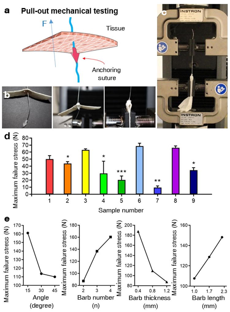
Tensile test for evaluating resistive force of 3D printed anchors from being pulled-out. a) A schematic of pull-out mechanical testing to examine the resistive force of the 3D printed anchor that was placed in an inverted position underneath the porcine tissue. b-c) Photo images showing process of tensile test to measure maximum failure stress of 3D printed anchors that are connected to stainless steel wires, which are fixed on the upper clamp of the mechanical tester. Inverted position of anchors were placed underneath swine skin pieces, which were fixed on the lower clamp of the mechanical tester. d) Maximum failure stress of nine types of anchors classified based on orthogonal arrays were examined by “pulling-out” tensile tests on swine skin (n=3). c) Tendency charts of the influence of individual factors from the orthogonal array, including slope angle between barbs, stem of the anchor, number of barbs, length of barbs, and thickness of barbs, on the maximum failure stress of 3D printed anchors, during being pulling-out. (*p <0.05, **p <0.01. ***p<0.001).
We further analyzed the effect of each influencing factor in orthogonal experiments on the maximum failure stress of anchors (Figure 3e, Table S1, Supporting Information). The results showed that the maximum resistive force of the anchor increased when the slope angle decreased, barb number increased, thickness of barb increased, and the length of barb decreased. In this respect, as the slope angle of the barb increases, greater stress will be loaded onto each individual barb, which can damage the barb. In other words, when the slope angle of the barb decreases, the net resistive force of the anchor increases. In addition, since the net resistive force of the anchor is symmetrically distributed into each barb, a greater number of barbs will generate stronger anchors that can effectively resist external forces. When the thickness of barbs increased, the maximum failure strength of barbs also increased. On the other hand, barbs with a longer length were easily broken before the anchors were pulled out.
As shown in the Figure S1 (Supporting Information), the net resistive force of the anchor (F) is n times greater than the individual resistive force of each barb (Fb), since we designed barbs in a symmetric manner. In each barb, Fb cos θ and Fb sin θ would act as a compressive force and pulling force of each barb, respectively, to resist slipping. When the opposite direction of the force is applied to the barb (F), both the resistive compressive force and the pulling force will damage the barbs. The pulling force will tend to strip the barb from the anchor through torsion, while the compressive force will break the anchor through stress. As a result, the pulling force will mostly damage the upper end of the barb which is connected the stem of the anchor, while the compressive force could damage the middle part of the barb. In this research, the slope angle of the barb on the anchor was controlled between 15° to 45°, in a range that cos θ has a greater value than sin θ We also observed that the damage was usually made in the middle of the barbs. Therefore, the major resistive force term that eventually caused damage to the barb during our experiments would be Fb cos θ.
Since the anchors should be easy to propagate following the needle direction, we also measured the maximum failure stress of nine types of samples by placing the tips of the anchors in a direction parallel with the pulling orientation (Figure 4a). The results showed that sample types 1 to 6 were easier to pull with less intensity of force compared to sample types 7 to 9 (Figure 4b). When we compared the effect of each variable, the mechanical force, barb numbers, and their slope angle were more influential than the thickness and length of barbs (Figure 4c, Table S2, Supporting Information). As the number of barbs and slope angle of barbs increased, the maximum failure stress tended to increase. In addition, samples 7 to 9 had a slope angle of the barbs of 45°, which critically increased maximum failure stress. Based on the evaluation of the maximum failure stress of anchors for pulling into the swine skin in both parallel and opposite direction to the needle direction, we concluded that sample type 6 is an optimal design because it had the greatest slip resistance while being relatively easy to penetrate along the needle.
Figure 4.
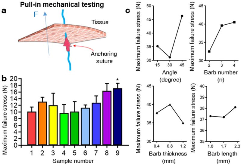
Tensile test for evaluating easiness of 3D printed anchors from being pulling-in. a) A schematic of pull-in mechanical testing to examine easiness of penetration of the 3D printed anchor that was placed underneath the porcine tissue, where the head of the anchor was contacting the tissue. b) Maximum failure stress of nine types of 3D printed anchors from orthogonal experiments, examined by “pulling-in” tensile test on swine skin (n=3). c) Tendency charts of the impact of each factor from the orthogonal array, including slope angle between barbs and stem of the anchor, number of barbs, length of barbs, and thickness of barbs, on the maximum failure stress of 3D printed anchors, during being pulled-in. (*p <0.05).
To assess if microstructured anchors were stably 3D printed without releasing toxic components, and cytocompatible, as a proof of concept investigation we cultured human mesenchymal stem cells (hMSCs) on top of 3D printed flat slabs that were composed of resin material identical to our anchors. After growing hMSCs on the top surface of flat slabs for 3 days, the viability of cells was evaluated by LIVE/DEAD assay (Figure 5a). The results showed that the resin had no cytotoxicity, since the viability of cells grown on resin material was 98.4%, while cells grown on the polystyrene cell culture microplate was 98.3%. The adhesion and spreading of cells was monitored after staining their nuclei and actin with DAPI and phalloidin, respectively (Figure 5b). The fluorescence images showed that there was no difference in cellular spreading behaviors between the resin material and control polystyrene microplate surface. In addition, we also examined the proliferation level of cells grown in DMEM which included resin extract (Figure 5c). The result showed that the resin material did not alter the proliferation rate of cells compared to DMEM alone. In future studies, in vivo tests are necessary to elucidate the biocompatibility and tissue fixation capacity of anchoring sutures, after optimizing the best material for fabrication.
Figure 5.

In vitro test and degradation test for measuring bioinertness and stability of 3D printed anchors. a-b) To test bioinertness of 3D printed anchors, viability of hMSCs was assessed after growing cells on (a) 3D printed flat slabs that were composed of resin material identical to 3D printed anchors and compared with (b) polystyrene cell culture microplates, 3 days after seeding cells. c-d) Spreading morphology of cells grown on (c) 3D printed flat slabs and (d) polystyrene cell culture microplates were observed under fluorescence microscope, after staining their nuclei and actin with DAPI and phalloidin, respectively. e) Proliferation test of hMSCs were conducted to measure the cytotoxicity of resin material, by adding resin extract in the media and comparing with normal media (n=3). f) Degradation behavior of 3D printed anchors were examined after immersing anchors in PBS media for up to 3 months (n=4). g) Stability of 3D printed anchors were evaluated after immersing anchors in distilled water and measuring their water adsorption ratio for up to 3 months (n=4). (*p <0.05).
Since one purpose of 3D printed anchors is the permanent or long-term fixation of tissues, we evaluated the degradability of the resin material after aging anchors in phosphate buffer saline (PBS) solution for up to 3 months (Figure 5d). Based on weight measurements, we verified that the anchors can maintain their shape and size. We also tested the surface stability of 3D printed anchors by measuring the water adsorption ratio, and confirmed that 3D printed micro-structures remain chemically stable for at least up to 3 months. Based on the optimal structural design of anchoring suture that can maximize its tissue fixation capacity we found in this study, we expect that biocompatible anchoring sutures can also be 3D printed by using FDA-approved biodegradable polymers such as poly(lactic-co-glycolic acid)[33] or nondegradable polymer such as poly(ethylene oxide).[34]
We then evaluated the tissue fixation function of our anchors by using swine ear, nose, and skin and bovine tendon structures ex vivo. In the current study, we used a commercial suture (4-0 polypropylene surgical suture (Prolene®, Ethicon)) as we focused on optimizing the design of the anchoring part for maximizing the tissue fixation capacity. Making one knot at the top and bottom of the anchor was sufficient to fix the position of the anchor along the suture. The distance between the anchors was controllable depending on the application purpose and thickness of the tissue. As shown in Figure 5a, we first simulated prominent ear surgery by using flat regions of swine ear, and tested if our anchors can induce curved ear without exposing its surface. A porcine ear had a thickness of 3 mm, and the distance between the two anchors was 8 mm. As shown in Figure 1a, we first folded the ear to have curvature, and then simultaneously inserted two ends of suture from the inner side of the ear tissue with approximately 2 mm distance, where the two anchors were directed parallel to the needle propagating orientation. As a result, two anchors faced opposite directions along the suture, as shown in Figure 1a. During this process, we aimed to not expose the suture by inserting two ends of the suture close to each other, at the inner end of the folded tissue. The sutures were tightly pulled until these anchors were placed in the cartilage tissue of the ear. While the anchors hold tissues in a folded form, the remaining sutures were cut and removed. After this minimally invasive suture insertion, the ear tissue maintained a folded form without exposing any part of suture or anchors. This is a novel method of prominent ear correction to restore the anti-helical fold in patients that have an underdeveloped fold. This suture method avoids the need for permanent alloy clips that are visible and palpable under the ear skin.
We also tested potential applications of our anchors for reconstructive surgery such as nose reshaping, as shown in Figure 1b and Figure 5b. We used anchoring sutures that had a similar arrangement that we used for ear reshaping surgery. After shaping the swine nose by hand, we measured the width of the nose, and optimized the distance between the two anchors on the surgical suture to approximately 4 cm. We first inserted both ends of the anchoring suture from one of the nasal fossae, and pulled one end to penetrate another nasal fossa at the top end of the nasal fossa. We then longitudinally penetrated both ends of the thread with two anchors through the swine nose towards opposite direction facing outward, while each anchor was placed at the internal ends of the nose. Afterwards, the shape of the nose was maintained solely by the anchoring capacity of the 3D printed bard suture. In addition, to simulate internal tissue surgery as shown in Figure 1c, we mimicked the cross-section of a stomach and determined whether we could decrease the area or volume of tissues by folding and holding local parts. The tissue fixing mechanism for decreasing the area of the cross-section of a stomach was similar to the ear reshaping and nose reshaping process. We used an anchoring suture that had two anchoring parts in different directions, with an approximate distance of 1 mm. On the inward side, we folded one part of the circular tissue to face outward, and inserted both ends of the anchoring suture to the opposite direction of the tissue. Like other tissue fixation processes, we then pulled out both ends of the suture to opposite directions, and held the tissue in a folded form. As shown in Figure 5c, we used swine skin to simulate weight loss surgery, and showed that the cross-sectional area of the tissue was reduced by folding and fixing the inner surface of tissue. This suture can also be used in situations where barbed sutures are frequently used, such as abdominal wound closure.
Finally, we examined if our anchor can hold load-bearing tissues by using bovine tendon structures (Figure 1d and Figure 4d). After cutting muscle tendon into two parts, six sites were stitched by sutures that were connected with anchors. Like other ex vivo tests, we used a suture with two anchors that are placed at opposite directions to hold the tissue tightly, and prevent sutures from slipping. For comparison, we did the same stitching procedure with general surgical sutures with double knotting, as well as commercial barbed sutures. From the tensile test, sutures with anchors demonstrated significantly higher maximum failure stress than other suture types.
4. Conclusions
We have determined an optimal design of suture anchors with maximum strength to hold reshaped tissue structures, and to permanently fix tissues in a minimally invasive manner, by utilizing 3D printing. By organizing orthogonal arrays and conducting ex vivo tensile tests, we found that the slope angle of barbs on anchors and the number of barbs were critical in determining factors of resistive capacity among other shape factors. In addition, our anchoring sutures with the optimized design endured greater load-bearing stress than knotted surgical sutures or barbed sutures. To solve the complexity of making knots for fixing anchors, in the future study, one can continuously print the suture and anchors, using a 3D multimaterial printer [29]. We expect that 3D printing can also be used for developing various designs of anchoring sutures for personalized treatment, particularly for the plastic surgery. We believe this study will contribute to the development of mechanically functional sutures that can minimize surgical invasiveness. We also expect that our systematic approach for determining the anchor shape can provide beneficial information related to designing other biomedical devices for medical therapeutic applications.
Supplementary Material
Figure 6.

Ex vivo test for assessing tissue shaping function of 3D printed anchoring suture. a) A flat swine ear was shaped into a folded morphology by inserting 3D printed anchoring sutures to demonstrate its potential for minimally invasive plastic surgery of the prominent ear. b) A stubby swine nose was reshaped into a convex morphology by inserting a 3D printed anchoring suture, to demonstrate its potential usage for minimally invasive reconstructive rhinoplasty. c) Swine skin was placed in a circular shape to simulate a cross-sectional view of stomach. 3D printed anchoring sutures was then used to hold the folded part of inner surface of swine skin to reduce the cross-sectional area, for demonstrating its potential application for weight loss surgery. d) Bovine Achilles tendon was divided into half, and 3D printed anchoring sutures were used to connect them without knotting process. e) Tensile test was conducted on reconnected bovine Achilles tendon to measure anchoring strength of 3D printed anchoring suture, compared to commercialized suture with knots and barbed suture (n=3). (*p <0.05, **p <0.01).
Acknowledgments
This work was supported by the National Institutes of Health (AR057837, AR070647).
Footnotes
Supporting Information:
Supporting Information is available from the Wiley Online Library or from the author.
Contributor Information
Wei Wei, Division of Engineering in Medicine, Department of Medicine, Biomaterials Innovation Research Center, Harvard Medical School, Brigham & Women’s Hospital, Boston, MA 02139, USA; Division of Health Sciences & Technology, Harvard-Massachusetts Institute of Technology, Massachusetts Institute of Technology, Cambridge, MA 02139, USA.
Prof. Yuxiao Li, Division of Engineering in Medicine, Department of Medicine, Biomaterials Innovation Research Center, Harvard Medical School, Brigham & Women’s Hospital, Boston, MA 02139, USA Division of Health Sciences & Technology, Harvard-Massachusetts Institute of Technology, Massachusetts Institute of Technology, Cambridge, MA 02139, USA.
Prof. Huazhe Yang, Division of Engineering in Medicine, Department of Medicine, Biomaterials Innovation Research Center, Harvard Medical School, Brigham & Women’s Hospital, Boston, MA 02139, USA Division of Health Sciences & Technology, Harvard-Massachusetts Institute of Technology, Massachusetts Institute of Technology, Cambridge, MA 02139, USA.
Dr. Reza Nassab, The Wilmslow Hospital, Wilmslow, Cheshire, SK9 1NY GB, UK
Fatemeh Shahriyari, Division of Engineering in Medicine, Department of Medicine, Biomaterials Innovation Research Center, Harvard Medical School, Brigham & Women’s Hospital, Boston, MA 02139, USA; Division of Health Sciences & Technology, Harvard-Massachusetts Institute of Technology, Massachusetts Institute of Technology, Cambridge, MA 02139, USA.
Ali Akpek, Division of Engineering in Medicine, Department of Medicine, Biomaterials Innovation Research Center, Harvard Medical School, Brigham & Women’s Hospital, Boston, MA 02139, USA; Division of Health Sciences & Technology, Harvard-Massachusetts Institute of Technology, Massachusetts Institute of Technology, Cambridge, MA 02139, USA.
Xiaofei Guan, Division of Engineering in Medicine, Department of Medicine, Biomaterials Innovation Research Center, Harvard Medical School, Brigham & Women’s Hospital, Boston, MA 02139, USA; Division of Health Sciences & Technology, Harvard-Massachusetts Institute of Technology, Massachusetts Institute of Technology, Cambridge, MA 02139, USA.
Yanhui Liu, Division of Engineering in Medicine, Department of Medicine, Biomaterials Innovation Research Center, Harvard Medical School, Brigham & Women’s Hospital, Boston, MA 02139, USA; Division of Health Sciences & Technology, Harvard-Massachusetts Institute of Technology, Massachusetts Institute of Technology, Cambridge, MA 02139, USA.
Shahrouz Taranejoo, Division of Engineering in Medicine, Department of Medicine, Biomaterials Innovation Research Center, Harvard Medical School, Brigham & Women’s Hospital, Boston, MA 02139, USA; Division of Health Sciences & Technology, Harvard-Massachusetts Institute of Technology, Massachusetts Institute of Technology, Cambridge, MA 02139, USA.
Dr. Ali Tamayol, Division of Engineering in Medicine, Department of Medicine, Biomaterials Innovation Research Center, Harvard Medical School, Brigham & Women’s Hospital, Boston, MA 02139, USA Division of Health Sciences & Technology, Harvard-Massachusetts Institute of Technology, Massachusetts Institute of Technology, Cambridge, MA 02139, USA; Wyss Institute for Biologically Inspired Engineering, Harvard University, Boston, MA 02115, USA.
Dr. Yu Shrike Zhang, Division of Engineering in Medicine, Department of Medicine, Biomaterials Innovation Research Center, Harvard Medical School, Brigham & Women’s Hospital, Boston, MA 02139, USA Division of Health Sciences & Technology, Harvard-Massachusetts Institute of Technology, Massachusetts Institute of Technology, Cambridge, MA 02139, USA; Wyss Institute for Biologically Inspired Engineering, Harvard University, Boston, MA 02115, USA.
Prof. Ali Khademhosseini, Division of Engineering in Medicine, Department of Medicine, Biomaterials Innovation Research Center, Harvard Medical School, Brigham & Women’s Hospital, Boston, MA 02139, USA Division of Health Sciences & Technology, Harvard-Massachusetts Institute of Technology, Massachusetts Institute of Technology, Cambridge, MA 02139, USA; Wyss Institute for Biologically Inspired Engineering, Harvard University, Boston, MA 02115, USA; Department of Bioindustrial Technologies, College of Animal Bioscience & Technology, Konkuk University, Seoul 143-701, Republic of Korea; Nanotechnology Center, King Abdulaziz University, Jeddah 21569, Saudi Arabia.
Dr. Hae Lin Jang, Division of Engineering in Medicine, Department of Medicine, Biomaterials Innovation Research Center, Harvard Medical School, Brigham & Women’s Hospital, Boston, MA 02139, USA Division of Health Sciences & Technology, Harvard-Massachusetts Institute of Technology, Massachusetts Institute of Technology, Cambridge, MA 02139, USA; Wyss Institute for Biologically Inspired Engineering, Harvard University, Boston, MA 02115, USA.
References
- 1.Dennis C, Sethu S, Nayak S, Mohan L, Morsi YY, Manivasagam G. J Biomed Mater Res Part B Appl Biomater. 2016;104:1544. doi: 10.1002/jbm.a.35683. [DOI] [PubMed] [Google Scholar]
- 2.Naleway SE, Lear W, Kruzic JJ, Maughan CB. J Biomed Mater Res Part B Appl Biomater. 2015;103:735. doi: 10.1002/jbm.b.33171. [DOI] [PubMed] [Google Scholar]
- 3.Seitz JM, Durisin M, Goldman J, Drelich JW. Adv Healthcare Mater. 2015;4:1915. doi: 10.1002/adhm.201500189. [DOI] [PubMed] [Google Scholar]
- 4.Manivasagam G, Dhinasekaran D, Rajamanickam A. Recent patents on corrosion science. 2010;2:40. [Google Scholar]
- 5.Yaltirik M, Dedeoglu K, Bilgic B, Koray M, Ersev H, Issever H, Dulger O, Soley S. Oral Dis. 2003;9:284. doi: 10.1034/j.1601-0825.2003.00954.x. [DOI] [PubMed] [Google Scholar]
- 6.Von Fraunhofer J, Chu C. Mechanical properties. Vol. 107. CRC Press; NY, USA: 1997. [Google Scholar]
- 7.Lin Y, Lai S, Huang J, Du L. Sci Rep. 2016;6:23425. doi: 10.1038/srep23425. [DOI] [PMC free article] [PubMed] [Google Scholar]
- 8.Greenberg J, Einarsson J. J Minim Invasive Gynecol. 2008;15:11S. doi: 10.1016/j.jmig.2008.06.004. [DOI] [PubMed] [Google Scholar]
- 9.Strasswimmer J, Latimer B, Speer H. JAMA Dermatol. 2013;149:853. doi: 10.1001/jamadermatol.2013.4142. [DOI] [PubMed] [Google Scholar]
- 10.Iavazzo C, Mamais I, Gkegkes ID. Surg Innov. 2015;22:528. doi: 10.1177/1553350614554235. [DOI] [PubMed] [Google Scholar]
- 11.Villa MT, White LE, Alam M, Yoo SS, Walton RL. Plast Reconstr Surg. 2008;121:102e. doi: 10.1097/01.prs.0000299452.24743.65. [DOI] [PubMed] [Google Scholar]
- 12.Greenberg JA, Goldman RH. Rev Obstet Gynecol. 2013;6:107. [PMC free article] [PubMed] [Google Scholar]
- 13.Rosenberg AG. presented at Semin Arthroplasty. 2013 Sep; [Google Scholar]
- 14.Kaul S, Sammon J, Bhandari A, Peabody J, Rogers CG, Menon M. J Urol. 2010;24:1789. doi: 10.1089/end.2010.0200. [DOI] [PubMed] [Google Scholar]
- 15.Paul MD. In: Innovations in Plastic and Aesthetic Surgery. Eisenmann-Klein M, Neuhann-Lorenz C, editors. Springer Berlin; Heidelberg: 2008. p. 235. [Google Scholar]
- 16.Ajcamo JH. US 3123077. 1964 [Google Scholar]
- 17.McKenzie A. Bone Joint J. 1967;49:440. [PubMed] [Google Scholar]
- 18.Lind JU, Busbee TA, Valentine AD, Pasqualini FS, Yuan H, Yadid M, Park S-J, Kotikian A, Nesmith AP, Campbell PH. Nat Mater. 2017;16:303. doi: 10.1038/nmat4782. [DOI] [PMC free article] [PubMed] [Google Scholar]
- 19.Paul MD. J Am Col Certif Wound Spec. 2009;1:51. doi: 10.1016/j.jcws.2009.01.002. [DOI] [PMC free article] [PubMed] [Google Scholar]
- 20.Ingle NP, King MW. J Biomech. 2010;43:302. doi: 10.1016/j.jbiomech.2009.08.033. [DOI] [PubMed] [Google Scholar]
- 21.Ingle NP, King MW, Zikry MA. J Biomech. 2010;43:879. doi: 10.1016/j.jbiomech.2009.11.012. [DOI] [PubMed] [Google Scholar]
- 22.Kirsch D, Marczyk S. US 8414612. 2013 [Google Scholar]
- 23.Hong X, Mahalingam S, Edirisinghe M. Macromol Mater Eng. 2017;302:1600564. [Google Scholar]
- 24.Ruff G. Aesthet Surg J. 2006;26:620. doi: 10.1016/j.asj.2006.08.011. [DOI] [PubMed] [Google Scholar]
- 25.Wu WT. Aesthet Surg J. 2004;24:582. doi: 10.1016/j.asj.2004.09.007. [DOI] [PubMed] [Google Scholar]
- 26.Isse NG, Fodor PB. Aesthet Surg J. 2005;25:301. doi: 10.1016/j.asj.2005.03.007. [DOI] [PubMed] [Google Scholar]
- 27.Zhang Y, Zhang F, Yan Z, Ma Q, Li X, Huang Y, Rogers JA. Nat Rev Mater. 2017;2:17019. [Google Scholar]
- 28.Pucci JU, Christophe BR, Sisti JA, Connolly ES. Biotechnol Adv. 2017;35:521. doi: 10.1016/j.biotechadv.2017.05.007. [DOI] [PubMed] [Google Scholar]
- 29.Liu W, Zhang YS, Heinrich MA, Ferrari FD, Jang HL, Bakht SM, Alvarez MM, Yang J, Li Y, Santiago GT, Miri AK, Khoshakhlagh P, Prakash G, Cheng H, Guan X, Zhong Z, Ju J, Zhu GH, Jin X, Shin SR, Dokmeci MR, Khademhosseini A. Adv Mater. 2017;29:1604630. doi: 10.1002/adma.201604630. [DOI] [PMC free article] [PubMed] [Google Scholar]
- 30.Jujun R, Jie Z, Jian H, Zhang J. Sci Rep. 2015;5:13481. doi: 10.1038/srep13481. [DOI] [PMC free article] [PubMed] [Google Scholar]
- 31.Cai C, Chen Y, Zhong S, Zhang Y, Jiang J, Xu H, Shi G. Sci Rep. 2016;6:27014. doi: 10.1038/srep27014. [DOI] [PMC free article] [PubMed] [Google Scholar]
- 32.Sullivan TP, Eaglstein WH, Davis SC, Mertz P. Wound Repair Regen. 2001;9:66. doi: 10.1046/j.1524-475x.2001.00066.x. [DOI] [PubMed] [Google Scholar]
- 33.Zhu W, Lee SJ, Castro NJ, Yan D, Keidar M, Zhang LG. Sci Rep. 2016;6:21974. doi: 10.1038/srep21974. [DOI] [PMC free article] [PubMed] [Google Scholar]
- 34.Subramaniam A, Sethuraman S. In: Natural and Synthetic Biomedical Polymers. Kumbar SG, Laurencin CT, Deng M, editors. Elsevier; Burlington, San Diego: 2014. p. 301. [Google Scholar]
Associated Data
This section collects any data citations, data availability statements, or supplementary materials included in this article.