Abstract
Noninvasive cardiac imaging has played a critical part in the evaluation, monitoring, and follow-up of structural heart disease. This review will highlight the role of cardiac computed tomography, fluoroscopy, and fusion imaging in guiding transcatheter aortic valve replacement and other percutaneous strategies used to diagnose and treat complex structural heart complications.
Keywords: transcatheter aortic valve replacement, TAVR, computed tomography, fusion imaging, fluoroscopy
TRANSCATHETER AORTIC VALVE REPLACEMENT
Computed Tomography
Individuals with aortic stenosis who are deemed inoperable or at high or intermediate risk for surgical intervention can now be offered transcatheter aortic valve replacement (TAVR) as a successful alternative. Due to the percutaneous nature of this technique, a high-quality, comprehensive, and accurate evaluation of the vasculature and aortic root are crucial for procedural planning and success. In a single test, computed tomography (CT) imaging allows comprehensive assessment of the coronaries, aortic root, thoracic and abdominal aorta, and bilateral iliac and common femoral arteries. Utility of CT is multifactorial and includes vascular assessment for selecting an appropriate access route (transfemoral, transapical, subclavian, transaortic); determination of aortic root and aortic annulus dimensions for appropriate valve and valve size selection; assessment of aortic valve structure and severity of calcification; and detection of coronary disease.
Image acquisition protocols vary based on differing detector systems. In general, expert consensus on CT data acquisition recommends imaging of the aortic root with electrocardiographic (ECG) synchronization, minimizing motion artifacts, obtaining a slice thickness of < 1 mm, imaging of the aorta and peripheral vessels from the aortic arch to below the groin, and judicious use of contrast agents.1 Our lab employs a dual-source CT scanner with improved temporal resolution and short examination times. With a single bolus of contrast, we perform a retrospective electrocardiography-gated acquisition of the heart and aortic root followed immediately by a high-pitch acquisition of the vasculature from the clavicles to the pelvis. Image acquisition is triggered automatically at a threshold of +100 HU with a region of interest selected in the descending thoracic aorta. Some sites also employ a noncontrast scan beforehand to further assess calcification of the valve and root. Total intravenous contrast volume is 70 mL to 90 mL (infused at 4–5 mL/s)—an important consideration in a population that usually has multiple risk factors for contrast-induced nephropathy. Dual-energy techniques allow further reductions in contrast dose. Radiation exposure is always minimized while maintaining acceptable image quality, although this is of secondary importance in this patient population. Routine administration of β-blockers or nitroglycerin is withheld due to concern for underlying severe aortic stenosis.
Aortic Annulus Imaging. Detailed measurements of the aortic annulus, a virtual ring formed by insertion of the aortic valve (AV) cusps into the left ventricular outflow tract (LVOT) wall, are fundamental for selecting transcatheter aortic valve prostheses. Currently, the most widely used method for reconstructing the AV annulus is based on sequential double oblique reconstructions.2 CT-derived measurements of the aortic annulus major/minor diameters, perimeter, and area are made in systole and help determine the correct prosthesis size (Figure 1 A). Appropriate sizing is critical since an undersized device may lead to embolization and paravalvular leak, while an oversized device may result in aortic rupture.3,4 Three-dimensional (3D) techniques have emphasized the oval shape of the annulus and consistently demonstrated larger dimensions compared to 2D echo techniques, which consistently visualize and measure the smaller diameter. Studies have indicated that CT-derived dimensions of the aortic annulus may improve procedural outcomes. A study of 133 patients who underwent CT before TAVR showed that prosthesis selection using CT-based aortic annulus dimensions led to a significantly lower rate of “worse-than-mild” paravalvular regurgitation compared to sizing with transesophageal echocardiography (TEE)-based dimensions (21.9% vs 7.5%).5
Figure 1.
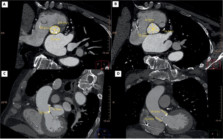
Standard measurements of the aortic root in pre-TAVR computed tomography. (A) Aortic annulus major/minor diameters and perimeter. (B) Sinus of Valsalva width. (C) Coronary ostia height. (D) Sinotubular junction height.
Aortic Valve Complex. Since the native valve leaflets are displaced into the aortic wall and the implanted prosthesis resides in the aortic root, comprehensive evaluation of the left ventricular outflow tract (LVOT), aortic valve, aortic root, and ascending thoracic aorta is also critical to implant success. This entails measuring the height of the coronary ostia from the annulus and the aortic valve cusp length and describing the extent and severity of LVOT and aortic valve calcification (Figure 1 B–D).1 A low origin of the coronary ostium, a bulky native valve, a shallow sinus of Valsalva, and prolonged left coronary leaflets have been shown to predict coronary occlusion by the native leaflets.6 Severity of LVOT calcification predicts potentially disastrous root injury. Other root measurements such as a sinus of Valsalva width/height and ascending aorta width (at 40 mm from the annulus) determine whether the prosthetic valve can be accommodated and are important for valve eligibility and selection. Bicuspid aortic valves are considered relative contraindications to TAVR.
Vascular Imaging. Vascular complications are a major cause of mortality and morbidity in TAVR, and CT routinely identifies risk factors related to vascular complications, including vessel lumen size, tortuosity, calcification, and peripheral vascular disease. Modern workstations can automatically extract vessel centerlines, display curved multiplanar reconstructions (MPRs) in orthogonal planes, and create true perpendicular axial images for manual or automated vessel caliber and stenosis measurements (Figure 2). Other advanced image processing with MPR, maximum intensity projections, and 3D volume-rendered images can be used for vessel analysis. A sheath-to-femoral-artery ratio of ≥ 1.05 has been associated with complications related to vascular access as well as 30-day mortality.7 The frequency of vascular complications increases 3-fold in the presence of arterial calcification (29% vs 9% in the absence of arterial calcification).8 Less than 180° of calcification and eccentric calcification is less likely to create procedural difficulty than circumferential or horseshoe calcification. The presence of significant peripheral vascular disease (PVD), such as tortuous aorta, dissection, arch atheroma, or protruding thrombi, may prevent the valve from advancing through the vasculature using the transfemoral approach; thus, identification of PVD aids in selecting alternative access routes (transapical, subclavian, or transaortic) for device implantation.9 A porcelain ascending aorta and retrosternal vein grafts from previous coronary artery bypass are usually contraindications to transaortic access.
Figure 2.
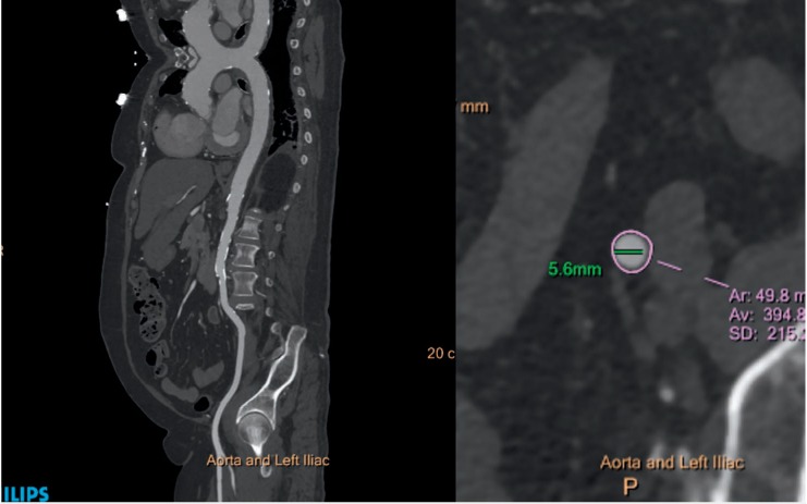
Computed tomography assessment of peripheral vasculature. Left panel: Curved multiplanar reconstruction of the thoracic and abdominal aorta and left iliac system showing no significant obstructive lesion and mild calcification. Right panel: Short-axis minimal luminal diameter of the left external iliac artery.
Coronary and Cardiac Imaging. CT is a very effective technique for evaluating the presence of concomitant coronary artery disease (CAD) with a high negative predictive accuracy. A recent review reported a 40% to 75% prevalence of CAD in the TAVR patient population.10 Ruling out the presence of obstructive disease (stenosis < 50%) can be beneficial to patients by decreasing the need for further invasive coronary angiography and its accompanying contrast and radiation risks. Septal LV hypertrophy and the angle between the aorta and the LV are important in planning the TAVR procedure. A septal bulge protruding into the LVOT makes it challenging for the operator to accurately place the prosthetic valve.
Fluoroscopy
Given its large field of view and high temporal resolution, fluoroscopy still represents the mainstay for intraoperative guidance imaging in patients undergoing TAVR. Accurate positioning and deployment are crucial for a successful implant. Positioning a valve prosthesis too high or too low may result in embolization, coronary obstruction, conduction disturbance, or paravalvular regurgitation. The optimal coaxial fluoroscopic implant view has all three coronary cusps in the same plane (right coronary cusp in the middle and the left and noncoronary cusp symmetrically to the left and right) and is perfectly perpendicular to the native valve annulus. Fluoroscopy-guided aortic root alignment can easily be performed using the “follow the right cusp rule” proposed by Kasel et al. or by utilizing the fluoroscopic angulation predicted by the preprocedural CT (thereby reducing contrast volume, radiation, and procedural time).11
A fluoroscopy-guided approach to TAVR may have several potential advantages. It overcomes the limitations of calcium- or device-related artifacts seen with TEE. In fact, fluoroscopy may rely on valve calcifications as anatomic reference points for prosthesis positioning and deployment. Fluoroscopy avoids the need for general anesthesia or rapid pacing (as is the case with TEE) and also reduces the contrast medium and total radiation load compared to intraprocedural CT.
Fusion Imaging
Fluoroscopic 2D imaging often does not provide sufficient anatomic detail or guidance to visualize the planned structural heart intervention. It has poor characterization of nonradiopaque structures and provides only 2D projections. In order to visualize all relevant planes, interventions are frequently performed using transesophageal or intracardiac echocardiography ultrasound along with x-ray imaging. CT's strength is detection of detailed anatomy, and it is now being integrated in real time into the catheterization lab with the registration of CT datasets using fluoroscopy or fusion imaging. An intraprocedural CT acquired by fluoroscopic C-arm (Syngo DynaCT, Siemens Healthcare) is first performed with or without contrast to localize the patient's position on the table.12 Preprocedural CT is then registered to the DynaCT using an automatic registration software package. Proper accuracy is verified based on unique anatomic features (cardiac prostheses, catheters, trachea, sternal wires, calcification, bones, etc.). Finally, the anatomic details of the preprocedural 3D CT information are superimposed on the real-time 2D fluoroscopic images to create a detailed procedural roadmap. With the rotation of the C-arm, the CTA image and landmarks move in real time, providing 3D anatomic information during the procedure.13 During TAVR, overlaying the aortic annulus on the fluoroscopic image helps identify the correct C-arm angulation that is perpendicular to the valve annulus. This ensures optimal valve positioning and deployment along the centerline of the aorta and perpendicular to the valve plane (Figure 3). The optimal position of the Edwards SAPIEN valve (Edwards Lifesciences Corp.) is 2 mm to 4 mm below the annular plane in the LVOT. The Medtronic CoreValve (Medtronic, Inc.) extends 5 mm to 10 mm below the annulus. Higher or lower placement of the valve may result in paravalvular regurgitation. The application of this technology may potentially increase the safety and accuracy of percutaneous cardiac procedures, employ less contrast material, and decrease the overall radiation dose.9
Figure 3.
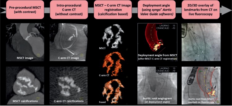
Workflow for fusion imaging in the catheterization lab. MSCT: multislice computed tomography; CT: computed tomography. Printed with permission from Ponraj Chinnadurai, MBBS, MMST, Siemens Medical Solutions USA, Inc.
MITRAL VALVE INTERVENTIONS
Echocardiography is considered the gold standard imaging modality for mitral valve (MV) assessment and guidance during interventions. However, CT's high spatial resolution offers the opportunity for detailed anatomic evaluation of the MV apparatus. Presence of mitral annular calcification, leaflet thickening and calcification, leaflet prolapse, and thickening of the chordae tendinae and papillary muscles can all be meticulously described. As visualized from the left atrium, a surgeon's view of the MV can easily be reconstructed for defect characterization and localization.14,15 Image acquisition with retrospective ECG gating and multiphase reconstruction allows one to create an image of the MV in motion during the entire cardiac cycle (4D cine), permitting image analysis analogous to echocardiography in both systole and diastole.16 Furthermore, a full, complementary evaluation of prosthetic MV dysfunction can also be readily performed with CT. Information on leaflet thickening/calcification/mobility, closing and opening angles of mechanical valves, thrombus and pannus detection, location of paravalvular leaks and complications from endocarditis can all be rapidly identified.
Paravalvular Leaks
Using surgical findings as the standard reference, CT has been shown to have diagnostic accuracy comparable to TEE for detection and localization of paravalvular leak (PVL).17 CT can accurately visualize the defect and define its spatial characteristics, including the region of the defect, size, shape, calcification, and whether or not the PVL has a serpiginous course. Since defect location subsequently impacts the interventionist's approach to the MV,18 3D reconstruction or 4D cines can further localize the defect with greater accuracy (Figures 4, 5). An antegrade transseptal approach is employed for anterolateral defects, whereas medial defects frequently require a retrograde transapical strategy.18 CT also guides intraprocedural PVL closure. As previously mentioned, fluoroscopy is limited by its 2D projections. With fusion imaging, high spatial information from the CT data set can be directly overlaid onto the fluoroscopy images. The precise localization of the paravalvular defect can then be displayed on the fluoroscopy screen and serve as a roadmap for catheter, wire, and device placement. Fusion imaging may also guide operators to the site of transseptal puncture or skin entry in the transapical approach, aiding in the safety and success of the procedure.16
Figure 4.
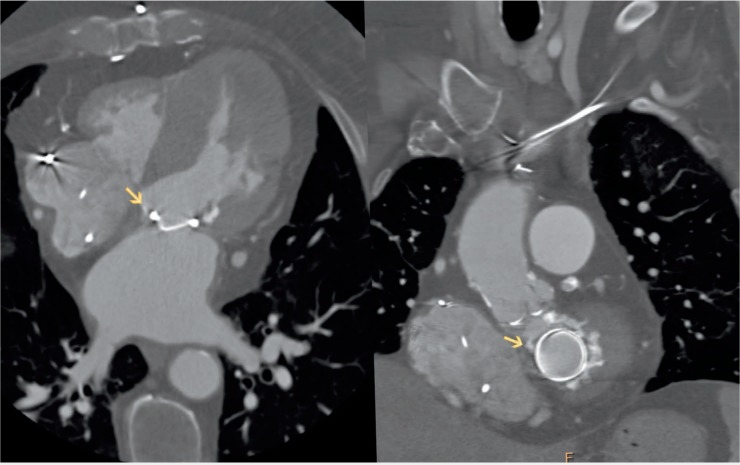
Computed tomography image of the paravalvular (PV) defect. Left panel: 4-chamber view of the heart showing medial PV defect. Right panel: Same defect located at 11 o'clock on an “en face” view of the mitral annulus.
Figure 5.
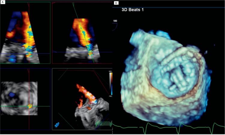
Three-dimensional transesophageal echocardiography images demonstrating the paravalvular defect. (A) Moderate-to-severe paravalvular mitral regurgitation. (B) Wire placement at 11 o'clock during paravalvular leak closure (same location as seen by computed tomography on Figure 4 left panel).
Valve-in-Valve Implantation
Computed tomography also plays a role in the procedural success of percutaneous valve-in-valve implantations. Internal diameter measurements of the failed prosthesis frame can be taken to determine accurate prosthesis sizing. The type of bioprosthesis, valve configuration (stented vs stentless), position (intra-annular vs supra-annular), leaflet bulkiness, and relationship to the LVOT all help determine the correct landing zone for implantation. The best fluoroscopic views facilitating accurate implantation are perpendicular to the bioprosthetic annular plane and permit coaxial transcatheter valve positioning. For failed valves, which are radiolucent, the structure of the prosthesis can be overlaid on fluoroscopy to provide a roadmap for intraprocedural guidance.19
Transcatheter Mitral Valve Replacement
Transcatheter Mitral Valve Replacement (TMVR) is emerging as a new treatment option in patients with advanced MV disease who are deemed to be at high or prohibitive risk for surgery. Similar to its use in TAVR, the usefulness of CT in MV interventions and new transcatheter MV technologies is in understanding the dynamic anatomy of the mitral apparatus and preprocedural planning. With acquisition of a 3D high spatial resolution data set, detailed measurements and description of mitral annular anatomy, leaflet anatomy, presence and extent of annular calcification, subvalvular apparatus (including papillary muscles and chordae), and surrounding structures (coronary sinus, left circumflex artery, LVOT) can be appreciated. Thus, anatomic inclusion and exclusion criteria for each of the technologies becoming available can be readily identified. The proposed D-shaped approach–in which the anterior horn of the mitral annulus is excluded–is used to size the annulus for device implantation.20 Annular area, perimeter, and specific distances are measured to help select a device size that has the lowest possible risk of paravalvular leakage and that will not jeopardize the integrity of the annulus or obstruct the LVOT. Risk factors that can be identified for LVOT obstruction include a small LV cavity (common in mitral stenosis), increased septal wall thickness, increased anterior leaflet length or bulk, or reduced aorto-mitral annular angle.21 Furthermore, CT allows for detailed geometric evaluation of the landing zone, which influences the success of the procedure including the degree of calcification of the annulus and leaflets. Finally, CT data can help derive appropriate coaxial angles of deployment and can be coregistered to angiographic data via fusion imaging at the time of the procedure for intraprocedural guidance.
LEFT ATRIAL APPENDAGE CLOSURE DEVICES
Left atrial appendage (LAA) closure devices, such as the WATCHMAN device (Boston Scientific Corporation) are approved by the U.S. Food and Drug Administration for use in patients with atrial fibrillation who are at high risk of stroke but have contraindications to long-term oral anticoagulation. Cardiac CT is an essential adjunctive tool to help plan percutaneous LAA closure and improve procedural success and safety. It provides valuable information about the presence or absence of thrombus and is helpful for preprocedural planning and postprocedure device surveillance.22,23
More than 90% of thrombi originate from the LAA. Although TEE is unequivocally the gold standard for thrombus detection, a major strength of CT is its high negative predictive value for excluding LAA thrombus.24 Thrombus detection is performed using a two-phase study, with a delayed second-phase scan performed 30 seconds after the first and covering only the region of interest.25 Any filling defect due to slow flow on the first scan will improve on the delayed scan, whereas a filling defect that persists on the delayed scan is more likely to represent a thrombus. Furthermore, thrombi typically appear as oval- or round-shaped filling defects, whereas incomplete mixing appears more as triangular-shaped.
Preprocedural planning for the WATCHMAN implant includes assessment of LAA shape and dimensions of the anatomical orifice. CT provides superior spatial resolution and image reconstruction compared to echocardiography and can therefore accurately characterize the anatomical properties.25 The shape of the LAA can be ascertained by viewing the volume-rendered images and is frequently classified into four distinct shapes as described by Wang et al.26 These shapes are categorized as windsock (single major lobe without significant bend), chicken-wing (obvious bend in the LAA body), cactus (major central lobe with multiple secondary lobes), and cauliflower (short LAA body that branches into several lobes). Ascertaining the LAA shape may help inform the operator about the potential complexity of device implantation. The choice and size of the LAA occluder device itself is dictated by the dimension and shape of the anatomical orifice of the LAA.27 Using multiplanar reformatted images, a cross-sectional orthogonal “end-on” view is created to measure the widest and narrowest diameters of the LAA ostium. The maximum depth of the LAA is measured from the orifice to the distal tip of the desired lobe. An important feature when implanting the WATCHMAN is that the depth of the distal lobe must be as deep as the diameter of the device chosen.27
CT can also be used instead of TEE as a reliable imaging modality for postprocedural device surveillance. The main role of CT in this context is to assess for device positioning and device-associated thrombus. It is also highly sensitive for detecting residual flow into the LAA by measuring CT attenuation (Figure 6).28 Peridevice leak detected by cardiac computed tomography angiography can be due to off-axis device implantation, gaps in the LAA orifice not covered by the device, and persistent fabric leak (likely due to incomplete endothelialization).28,29
Figure 6.
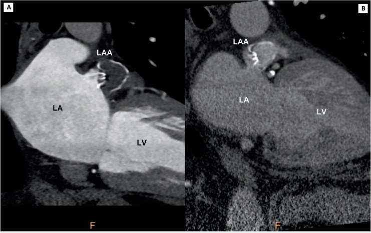
Computed tomography imaging of left atrial appendage (LAA) WATCHMAN closure device. (A) Successfully thrombosed LAA appendage. (B) Persistent filling of left atrial appendage. LA: left atrium; LV: left ventricle
KEY POINTS
Computed tomography (CT) is instrumental to the complication-free success of TAVR procedures by correctly guiding prosthesis size selection and identifying hostile vascular and aortic root anatomy.
Use of fusion imaging, where 3D CT images are overlaid on 2D fluoroscopic images, provides a useful roadmap for intraprocedural guidance and aids in the success of transcatheter interventions.
CT's high spatial resolution has made it a useful adjunct for planning prior to complicated MV and left atrial appendage interventions.
Footnotes
Conflict of Interest Disclosure: The authors have completed and submitted the Methodist DeBakey Cardiovascular Journal Conflict of Interest Statement and none were reported.
REFERENCES
- 1. Achenbach S, Delgado V, Hausleiter J, Schoenhagen P, Min JK, Leipsic JA.. SCCT expert consensus document on computed tomography imaging before transcatheter aortic valve implantation (TAVI)/transcatheter aortic valve replacement (TAVR). J Cardiovasc Comput Tomogr. 2012. Nov-Dec; 6 6: 366– 80. [DOI] [PubMed] [Google Scholar]
- 2. Leipsic J, Gurvitch R, Labounty TM, . et al. Multidetector computed tomography in transcatheter aortic valve implantation. JACC Cardiovasc Imag. 2011. April; 4 4: 416– 29. [DOI] [PubMed] [Google Scholar]
- 3. Gilard M, Eltchaninoff H, Iung B, . et al. Registry of transcatheter aortic-valve implantation in high-risk patients. N Engl J Med. 2012. May 3; 366 18: 1705– 15. [DOI] [PubMed] [Google Scholar]
- 4. Kodali SK, Williams MR, Smith CR, . et al. Two-year outcomes after transcatheter or surgical aortic-valve replacement. N Engl J Med. 2012. May 3; 366 18: 1686– 95. [DOI] [PubMed] [Google Scholar]
- 5. Jilaihawi H, Kashif M, Fontana G, . et al. Cross-sectional computed tomographic assessment improves accuracy of aortic annular sizing for transcatheter aortic valve replacement and reduces the incidence of paravalvular aortic regurgitation. J Am Coll Cardiol. 2012. April 3; 59 14: 1275– 86. [DOI] [PubMed] [Google Scholar]
- 6. Webb JG, Dvir D. Transcatheter aortic valve replacement for bioprosthetic aortic valve failure: the valve-in-valve procedure. Circulation. 2013. June 25; 127 25: 2542– 50. [DOI] [PubMed] [Google Scholar]
- 7. Hayashida K, Lefèvre T, Chevalier B, . et al. Transfemoral aortic valve implantation: new criteria to predict vascular complications. JACC Cardiovasc Interv. 2011. August; 4 8: 851– 8. [DOI] [PubMed] [Google Scholar]
- 8. Toggweiler S, Gurvitch R, Leipsic J, . et al. Percutaneous aortic valve replacement: vascular outcomes with a fully percutaneous procedure. J Am Coll Cardiol. 2012. January 10; 59 2: 113– 8. [DOI] [PubMed] [Google Scholar]
- 9. Rodes-Cabau J, Webb JG, Cheung A, . et al. Transcatheter aortic valve implantation for the treatment of severe symptomatic aortic stenosis in patients at very high or prohibitive surgical risk: acute and late outcomes of the multicenter Canadian experience. J Am Coll Cardiol. 2010. March 16; 55 11: 1080– 90. [DOI] [PubMed] [Google Scholar]
- 10. Goel SS, Ige M, Tuzcu EM, . et al. Severe aortic stenosis and coronary artery disease—implications for management in the transcatheter aortic valve replacement era: a comprehensive review. J Am Coll Cardiol. 2013. July 2; 62 1: 1– 10. [DOI] [PubMed] [Google Scholar]
- 11. Kasel AM, Cassese S, Bleiziffer S, . et al. Standardized imaging for aortic annular sizing: implications for transcatheter valve selection. JACC Cardiovasc Imag. 2013; 6 2: 249– 62. [DOI] [PubMed] [Google Scholar]
- 12. Krishnaswamy A, Tuzcu EM, Kapadia SR.. Integration of MDCT and fluoroscopy using C-arm computed tomography to guide structural cardiac interventions in the cardiac catheterization laboratory. Catheter Cardiovasc Interv. 2015; 85 1: 139– 47. [DOI] [PubMed] [Google Scholar]
- 13. Krishnaswamy A, Tuzcu EM, Kapadia SR.. Three-dimensional computed tomography in the cardiac catheterization laboratory. Catheter Cardiovasc Interv. 2011; 77 6: 860– 5. [DOI] [PubMed] [Google Scholar]
- 14. Ghersin N, Abadi S, Sabbag A, . et al. The three-dimensional geometric relationship between the mitral valvar annulus and the coronary arteries as seen from the perspective of the cardiac surgeon using cardiac computed tomography. Eur J Cardiothorac Surg. 2013. December; 44 6: 1123– 30. [DOI] [PubMed] [Google Scholar]
- 15. Jelnin V, Kliger C, Zucchetta F, Ruiz CE.. Use of computed tomography to guide mitral interventions. Interv Cardiol Clin. 2016. January; 5 1: 33– 43. [DOI] [PubMed] [Google Scholar]
- 16. Sherif MA, Abdel-Wahab M, Stocker B, . et al. Anatomic and procedural predictors of paravalvular aortic regurgitation after implantation of the Medtronic CoreValve bioprosthesis. J Am Coll Cardiol. 2010. November 9; 56 20: 1623– 9. [DOI] [PubMed] [Google Scholar]
- 17. Lesser JR, Han BK, Newell M, Schwartz RS, Pedersen W, Sorajja P.. Use of cardiac CT angiography to assist in the diagnosis and treatment of aortic prosthetic paravalvular leak: a practical guide. J Cardiovasc Comput Tomogr. 2015. May-Jun; 9 3: 159– 64. [DOI] [PubMed] [Google Scholar]
- 18. Blanke P, Dvir D, Naoum C, . et al. Prediction of fluoroscopic angulation and coronary sinus location by CT in the context of transcatheter mitral valve implantation. J Cardiovasc Comput Tomogr. 2015. May-Jun; 9 3: 183– 92. [DOI] [PubMed] [Google Scholar]
- 19. Webb JG, Dvir D. Transcatheter aortic valve replacement for bioprosthetic aortic valve failure: the valve-in-valve procedure. Circulation. 2013. June 25; 127 25: 2542– 50. [DOI] [PubMed] [Google Scholar]
- 20. Blanke P, Dvir D, Cheung A, . et al. Mitral Annular Evaluation With CT in the Context of Transcatheter Mitral Valve Replacement. JACC Cardiovasc Imag. 2015. May; 8 5: 612– 15. [DOI] [PubMed] [Google Scholar]
- 21. Tang GH, George I, Hahn RT, Bapat V, Szeto WY, Kodali SK.. Transcatheter mitral valve replacement: design implications, potential pitfalls and outcomes assessment. Cardiol Rev. 2015. Nov-Dec; 23 6: 290– 6. [DOI] [PubMed] [Google Scholar]
- 22. Saw J, Fahmy P, Azzalini L, . et al. Early Canadian Multi-Center Experience with WATCHMAN for Percutaneous Left Atrial Appendage Closure. J Cardiovasc Electrophysiol. 2017. April; 28 4: 396– 401. [DOI] [PubMed] [Google Scholar]
- 23. Piccini JP, Sievert H, Patel MR.. Left atrial appendage occlusion: rationale, evidence, devices, and patient selection. Euro Heart J. 2017. March 21; 38 12: 869– 76. [DOI] [PubMed] [Google Scholar]
- 24. Kim YY, Klein AL, Halliburton SS, . et al. Left atrial appendage filling defects identified by multidetector computed tomography in patients undergoing radiofrequency pulmonary vein antral isolation: a comparison with transesophageal echocardiography. Am Heart J. 2007. December; 154 6: 1199– 205. [DOI] [PubMed] [Google Scholar]
- 25. Rajwani A, Nelson AJ, Shirazi MG, . et al. CT sizing for left atrial appendage closure is associated with favourable outcomes for procedural safety. Eur Heart J Cardiovasc Imaging. 2016. December 24; pii: jew212. [DOI] [PubMed] [Google Scholar]
- 26. Wang Y, Di Biase L, Horton RP, Nguyen T, Morhanty P, Natale A.. Left atrial appendage studied by computed tomography to help planning for appendage closure device placement. J Cardiovasc Electrophys. 2010. September; 21 9: 973– 82. [DOI] [PubMed] [Google Scholar]
- 27. Wang DD, Eng M, Kupsky D, . et al. Application of 3-dimensional computed tomographic image guidance to watchman implantation and impact on early operator learning curve: single-center experience. JACC Cardiovasc Interv. 2016. November 28; 9 22: 2329– 40. [DOI] [PubMed] [Google Scholar]
- 28. Saw J, Lopes JP, Reisman M, McLaughlin P, Nicolau S, Bezerra HG.. Cardiac computed tomography angiography for left atrial appendage closure. Can J Cardiol. 2016. August; 32 8: 1033.e1– 9. [DOI] [PubMed] [Google Scholar]
- 29. Saw J, Fahmy P, Spencer R, . et al. Comparing measurements of CT angiography, TEE, and fluoroscopy of the left atrial appendage for percutaneous closure. J Cardiovasc Electrophysiol. 2016. April; 27 4: 414– 22. [DOI] [PubMed] [Google Scholar]


