Abstract
Electronic systems harboring one-dimensional helical modes, where spin and momentum are locked, have lately become an important field of its own. When coupled to a conventional superconductor, such systems are expected to manifest topological superconductivity; a unique phase hosting exotic Majorana zero modes. Even more interesting are fractional helical modes, yet to be observed, which open the route for realizing generalized parafermions. Possessing non-abelian exchange statistics, these quasiparticles may serve as building blocks in topological quantum computing. Here, we present a new approach to form protected one-dimensional helical edge modes in the quantum Hall regime. The novel platform is based on a carefully designed double-quantum-well structure in a GaAs based system hosting two electronic sub-bands; each tuned to the quantum Hall effect regime. By electrostatic gating of different areas of the structure, counter-propagating integer, as well as fractional, edge modes with opposite spins are formed. We demonstrate that due to spin-protection, these helical modes remain ballistic for large distances. In addition to the formation of helical modes, this platform can serve as a rich playground for artificial induction of compounded fractional edge modes, and for construction of edge modes based interferometers.
Pursuing Majorana-zero-modes (MZMs) in condensed matter physics is gaining wide range interest1–9. While bearing some resemblance to their high energy counterparts, condensed matter MZMs are significantly different as they are expected to possess non-abelian exchange statistics, which renders them as potential candidates for topologically protected qubits2,10–15. One of the most promising platforms for the formation of MZMs is a one-dimensional helical system coupled to an s-wave superconductor16,17. In a helical system, electrons moving in opposite directions possess opposite spins (spin degeneracy is lifted), while the two original spin species are still present. Their coupling to an s-wave superconductor, induces topological, ‘spinless’, p-wave pairing. At the two ends of the induced superconductor, two localized MZMs are expected to form. Even more interesting are the generalized para-fermions, which are expected to emerge when coupling a conventional superconductor to helical modes in the fractional quantum Hall effect regime18–20.
Most of the present attempts to form helical modes concentrate in materials with strong spin-orbit coupling5–9,21–25. While signatures of localized MZMs appeared, the helical nature of the underlying modes is not confirmed. Lately, the presence of helical edge modes was reported in small size (edge length of ~350nm) 2D topological insulators21–23, as well as in a twisted bilayer graphene in the IQHE regime (of size ~15µm)26. Another work attempted to form helical modes by doping with magnetic impurities quantum wells and electrostatically inducing ferromagnetic transitions27. However, in these works spin-protection from backscattering was not reported and strong inter-mode mixing limited the propagation length. Moreover, the formation of fractional helical modes was not reported yet.
We developed a new platform that enables formation of robust and highly controllable helical modes in the QHE effect regime. The platform is based on a two-dimensional electron gas (2DEG) embedded in a double-quantum-well (DQW), which hosts two electronic sub-bands. By a proper electrostatic gating of two adjacent half-planes of the 2DEG, spin-split Landau levels (LLs), belonging to the different sub-bands, cross each other at the interface between the two half-planes forming counter propagating edge modes at the same lateral place. When the intersecting LLs are of opposite spins, the formed counter-propagating modes are helical.
One should note the difficulty in obtaining counter-propagating edge states with opposite spins in the QHE regime (see Supplementary Information - 1; SI1). Several works dating back to 1988 have demonstrated same spin counter propagating edge profile by utilizing a series of alternating filling factors28. In such realizations helical states scenarios are not accessible. In this work we demonstrate complete control over individual spins by inter-edge tunneling, both in the integer as well as at the fractional regime.
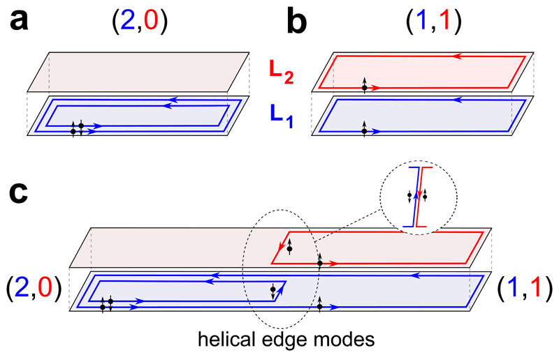
Figure 1 illustrates schematically the formation of helical edge modes in the two sub-bands of the quantum Hall system. The sub-bands, denoted by SB1 and SB2, are depicted as two 2-dimentional sheets (blue for SB1 and red for SB2). Each sub-band splits to discrete LLs at high magnetic field, with individual filling factors, v1 in SB1 and in v2 SB2; with a generalized defined filling factor v = (v1,v2). Figures 1a & 1b describe the scenarios of v = (2,0) and v = (1,1), respectively. When these two configurations are placed one next to the other, as shown in Fig. 1c, counter-propagating chiral edge modes, with opposite spins, propagate along the interface (spin-down in SB1, blue, and spin-up in SB2, red), manifesting integer helical edge modes.
Figure 1. Schematic illustration of the concept of creating helical edge modes in a double-layer quantum Hall effect system.
Two 2DEGs are shown, one in blue denoted by SB1, and one in red denoted by SB2. Each layer has its own filling factor, v1 and v2, respectively. The double-layer generalized filling denoted is v = (v1,v2). a, Scenario of v = (2,0), with two edge modes propagating at the edge of SB1. b, Scenario of v = (1,1), with one edge modes propagating at the edge of SB1 and one at the edge of SB2. c, The left half-plane is in v = (2,0) and the right half-plane is in v = (1,1). This creates counter propagating edge modes with opposite spins at the interface between the two half-planes (see inset).
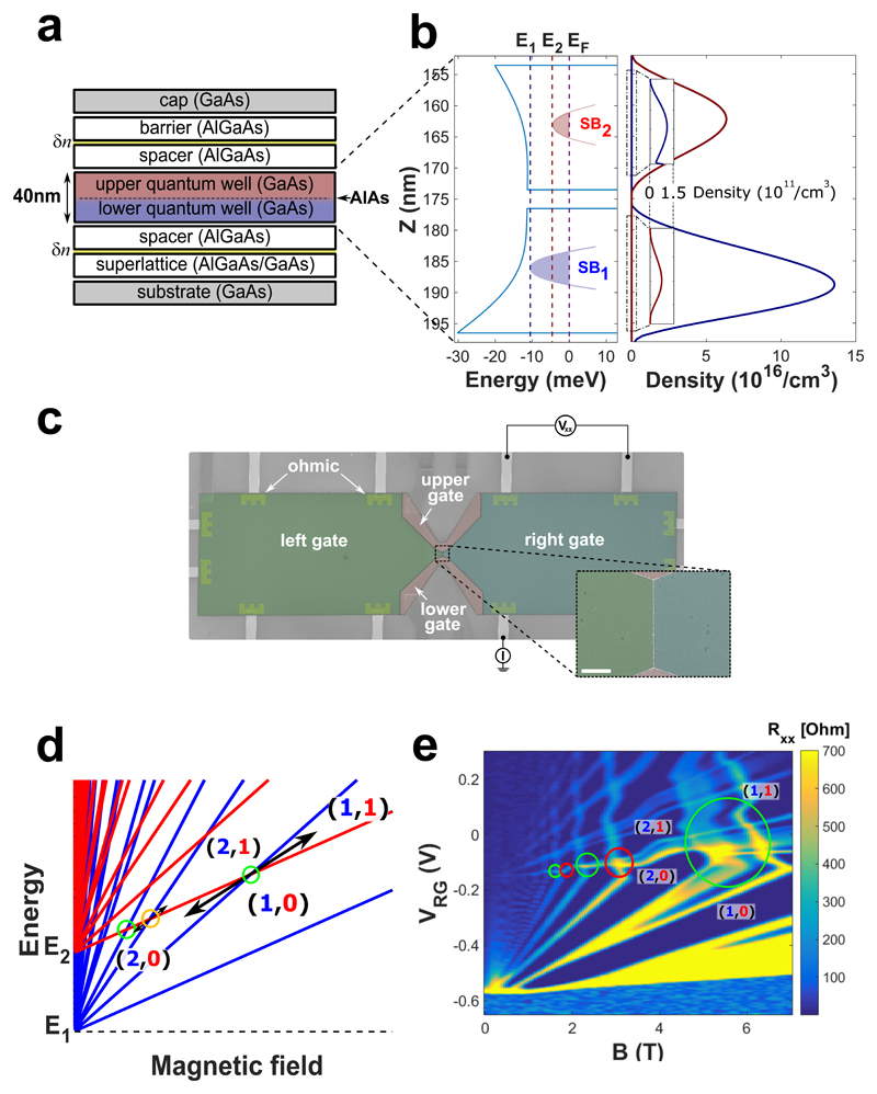
Figure 2a shows a schematic illustration of the heterostructure used to implement the two sub-bands system. A 40nm thick GaAs layer, cladded on top and bottom by AlGaAs layers, forms the quantum well structure. A thin AlAs barrier, 3nm thick, is inserted in the middle of the GaAs layer to form a DQW potential landscape. The total areal density at zero gate voltage is n = 2.7×1011cm−2 and the low temperature mobility is μ = 0.6×106cm2V−1s−1. Modulation doping, predominantly at the lower side of the DQW, leads to a tilted potential in the well (self-consistent simulation in Fig. 2b). A top-view SEM image in Fig. 2c shows a fabricated structure with its top-gates, dividing the surface to two adjacent half-planes. All measurements were performed at a base temperature of 15mK using a standard Lock-In technique at a frequency of 37Hz. Each line, located on the cold finger of the cryostat and cooled to base temperature, was filtered by a cascade of three pi-filters followed by an RC filter.
Figure 2. MBE growth sequence, lithographic patterning, and actual fan diagram.
a, Growth sequence of the double quantum well heterostructure. The lower and upper GaAs quantum wells are colored in blue and red, respectively. Each well is ~20nm wide with a 3nm AlAs barrier separating them. b, NextNano3 simulation of the potential landscape and the SBs’ energies as well as charge distributions at zero magnetic field. The simulation was done with a total density of 2.2 1011/cm2, which is in the range of densities and magnetic field relevant to filling factors v=1-4. Densities in the two sub-bands are about 1.5 & 0.7 1011/cm2 in SB1 & SB2, respectively. c, False colors SEM image of the device. Mesa size is 800µm long and 200µm wide with a narrower region of 7µm in the center, where the left and right top gates interface. The inset shows a zoom on the interface between the left and right top gates where the helical edge modes are designed to emerge (scale-bar 2µm). Note, the four top gates allow changing the configurations with the gates’ voltage and thus also increasing the propagation length of the counter-propagating modes. d, Ideal energy fan diagram for the two-layer 2DEG. The energies of the LLs of SB1 (blue) and SB2 (red) are plotted as a function of magnetic field. e, Measurement of the longitudinal resistance, RXX, of the right half of the device as a function of magnetic field and gate voltage VRG. The circles mark regions of LLs crossings with either opposite spins (green circles) or same spins (red circles). Measurements were performed at a base temperature of 15mK.
The fundamental difficulty in realizing the proposed configuration is illustrated schematically Fig. 2d, where a naïve illustration of the energy dependence of the LLs (in SB1 and in SB2) is plotted as function of magnetic field. Two different generalized fillings; e.g., (2,0) and (1,1), each in a different half-plane, cannot coexist in a single magnetic field. However, in practice the situation is different. As the energy of different LLs (in different sub-bands) cross, charge must redistribute between the sub-bands29,30. The charge redistribution leads to bending of the linear-like evolution of the LLs’ fan-diagram, allowing, under a proper design, for two generalized fillings (with equal sums of the individual fillings on both sides) to take place at the same magnetic field (Fig. 2e). Note, that charge transfer costs an additional energy since it leads to built-in electric field that charges the mutual capacitance between the two regions of the DQW where the different LLs reside - thus partly opposing the charge transfer29,30. A narrower DQW is desirable for a larger charge transfer, and thus a more pronounced bending of the LLs with magnetic field away from the linear evolution.
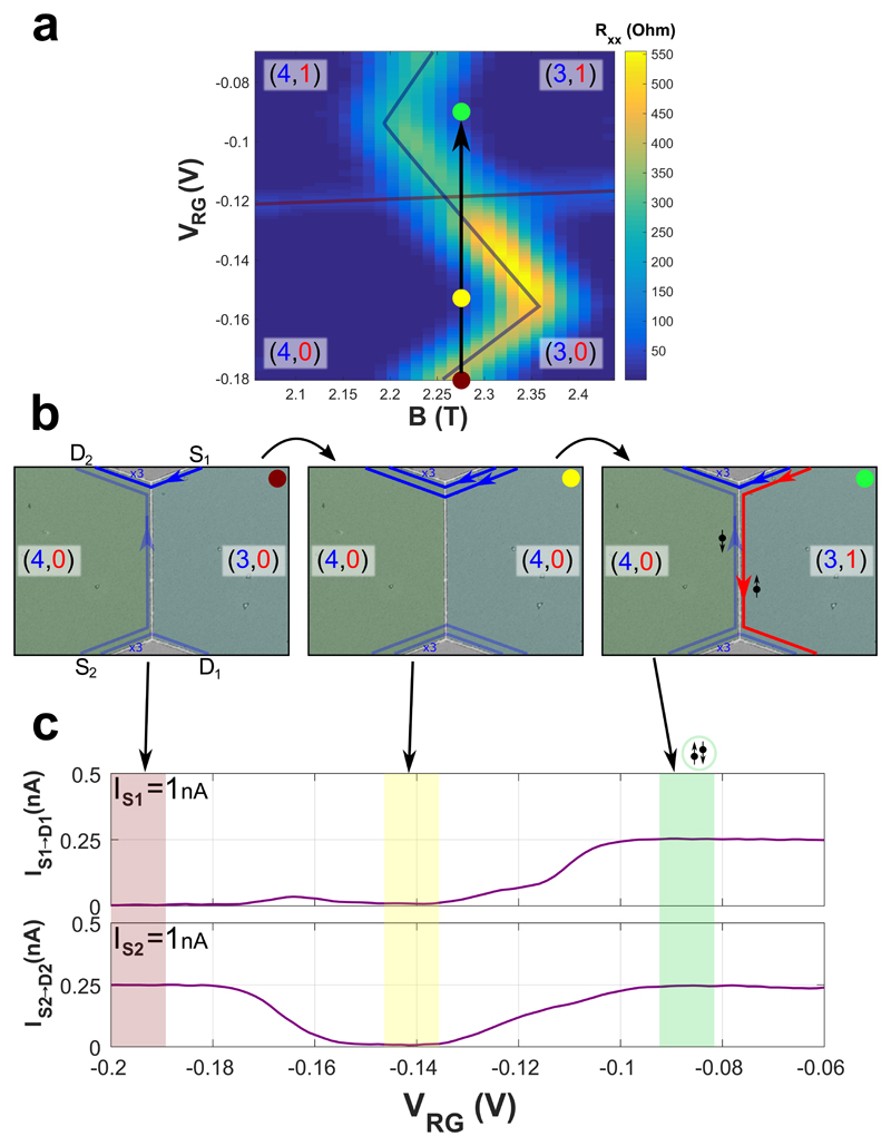
The fan-diagram of the longitudinal resistance (which follows the actual evolution of the LLs) is plotted in Fig. 2e. As the top gate voltage rises above -0.15V, LLs gradually fill and charge transfers from SB1 to SB2 (as LLs cross). LLs in SB1 lose carriers, thus shifting to lower magnetic fields (having a negative slope around the crossing regions). In the present configuration, there are multiple filling fractions between v=2 and v=1; hence, the charge transfer near the crossings of LLs is not large enough to allow a gate-controlled transition (2,0) → (1,1); yet, a transition (4,0) → (3,1) can be achieved (Fig. 3a). With B = 2.275T and VLG = −0.158V, the filling factor at the left half-plane is v = (4,0), while scanning VRG along the black arrow varies the filling on the right (3,0) → (4,0) → (3,1) (Fig. 3b).
Figure 3. Tuning the structure to host integer helical modes.
a, Longitudinal resistance, RXX, of the right half-plane of the device as a function of magnetic field and gate voltage, VRG, near the (4,0) → (3,1) transition. b, An illustration of the edge modes when the left side is set to (4,0) and the right side is scanned along the black arrow, i.e. from (3,0) (red point) through (4,0) (yellow point) to (3,1) (green point). c, The top graph corresponds to the measured reflected current in D1 when a current of 1nA is injected at contact S1, with the left half-plane is held at (4,0) and the gate voltage VRG is scanned. The red, yellow, and green shaded regions mark the range of gate voltage leading to fillings (3,0), (4,0) and (3,1) at the right half-plane. The bottom figure shows the measured current at D2 when 1nA is injected at S2. Colored regions were chosen according to Rxx=0.
A current of 1nA is injected at S1 and its reflected part, IS1→D1, is plotted in Fig. 3c (upper panel). With the left half-plane at (4,0), and the right half-plane tuned to (3,0) or (4,0), all the injected edge modes circulate the outer perimeter of the 2D plane, arriving at D2, while IS1→D1 = 0. When the right half-plane is tuned to (3,1), three edge modes arrive at D2 while an helical mode flows across the interface. One edge mode (LL in SB2, red line in right figure of Fig. 3b) is fully reflected to D1, with IS1→D1 = 0.25nA. Similarly, injecting current at S2 and measuring IS2→D2, leads to a complimentary result (Fig. 3c, lower panel). These observations agree with ballistic propagation of helical modes without inter-mode scattering (Fig. 3c, green shaded region).
The transition (4,0) → (3,1) is evidently only one example where interlayer charge transfer is sufficiently large to allow the formation of helical modes. Figure 2e shows four such transitions (n,0) → (n − 1,1) with n=3, 4, 5, 6, which allow gate-controlled transitions (open circles). Transitions with an even n, such as (4,0) → (3,1) and (6,0) → (5,1) (green circles), lead to helical modes. Same-spin counter-propagating modes are born with the transitions (3,0) → (2,1) or (5,0) → (4,1) (red circles).
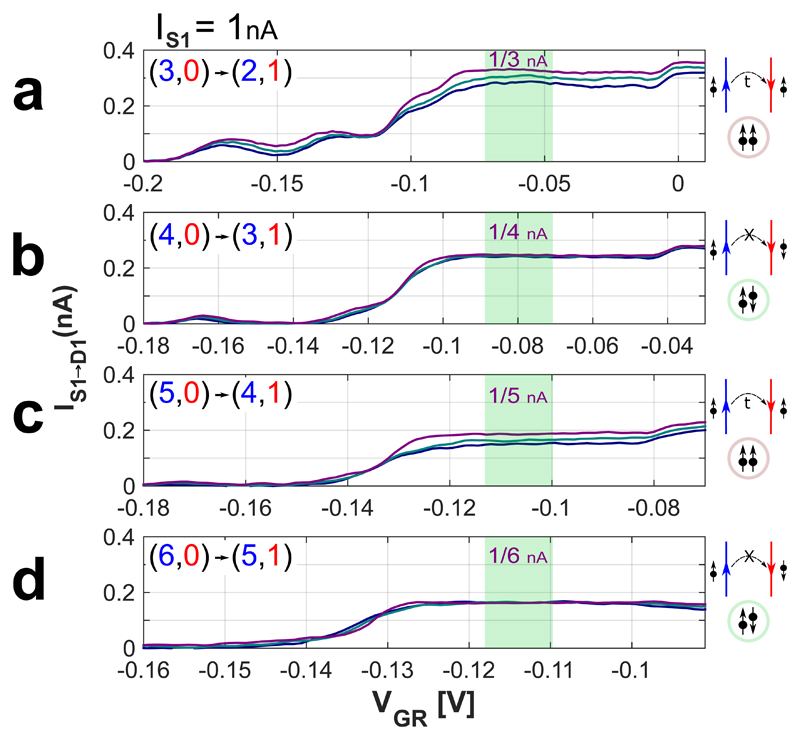
In Fig. 4 measurement results of IS1→D1 are plotted for the four transitions in devices with three different counter-propagation lengths, LCP=7µm, 150µm, and 300µm. A clear difference is observed between same-spin transitions (odd,0) → (even,1) and opposite-spin transitions (even,0) → (odd,1). In the former case, as LCP increases beyond 7µm a reduction in IS1→D1 is observed. The reduction in IS1→D1 is fully compensated by an increase in IS1→D2 (see SI, section S1), proving that inter-mode equilibration takes place (due to tunneling), with equilibration length of ~1mm (with no bulk current). In contrast, when helical modes are formed, no reduction in IS1→D1 is observed, even for LCP=300µm - demonstrating spin protection. (Additional measurements can be found in SI2).
Figure 4. Spin protected inter-mode tunneling.
a-d, Measurements of the reflected current reaching contact D1 when current is injected at contact S1 for different filling factors. In all measurements the left half-plane is held at (n, 0) while the right half-plane is scanned from (n-1, 0), through (n, 0) and to (n-1, 1), where n=3,4,5,6 in a, b, c and d, respectively. The shaded green regions mark the gate voltage range in which counter-propagating intersecting edge modes are formed. The different colors, purple, green and blue, correspond to three propagation lengths, LCP=7, 150, 300µm, respectively. When n is odd the two edge modes have the same spin, while where n is even the two edge modes have opposite spins. Evidently, while inter-mode tunneling is evident for same-spin configurations, transport remains ballistic even for LCP=300µm for opposite spin configuration.
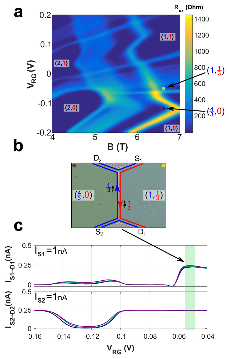
We turn to the fractional regime and concentrate on RXX in the B-VRG plane around the (2,0) → (1,1) transition (Fig. 5a). The red and yellow dots, which stand for and (1,⅓), respectively, allow an intersection of counter-propagating edge modes with opposite spins; each with filling v=⅓ (Fig. 5b). Indeed in the appropriate range of VRG, the currents IS1→D1 & IS2→D2 are both found to be 0.25nA (Fig. 5c, green regions). Note that while IS2→D2 is not affected by the propagation length, IS1→D1 decreases slightly as the propagation length increases. Since a corresponding increase in IS1→D2 is not observed, the missing current evidently flows through the bulk of the right half-plane due to a finite RXX (see SI3).
Figure 5. Formation of fractional helical states.
a, Fan diagram of the longitudinal resistance, RXX, of the right half-plane of the device as a function of magnetic field and gate voltage, VRG, in the transition region (2,0) → (1,1). Fractional quantum Hall states are clearly observed within the regions of the integer states. The red and yellow dots correspond to filling factors (4/3,0) and (1,1/3), respectively. b, An illustration of the formed fractional helical modes. c, The top (bottom) graph displays the current reaching D1 (D2), when current is injected at S1 (S2), while the left half-plane is tuned to (4/3,0) and the right half-plane is scanned. The shaded green regions correspond to the voltage range in which the right side is at (1,1/3). Both currents reach 0.25nA (with the 1/3 mode being fully reflected at both half-planes). The colors, purple, green and blue, correspond to three propagation lengths, LCP=7, 150, 300µm, respectively
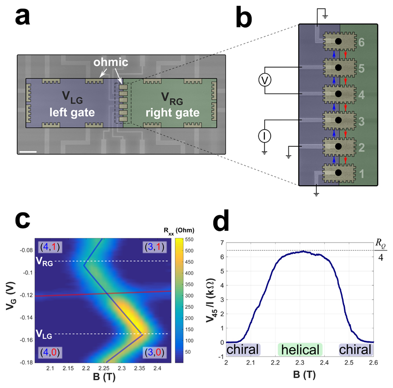
Finally, by directly contacting the helical modes, establishing thus a common Fermi energy in the two counter-propagating modes (Fig. 6a), four-terminal measurements can be performed (Fig. 6b). Current I is injected in contact #3 while contacts #1, #2 and #6 are grounded. The ratio between the potential difference between contacts #4 and #5, V45, and the current I is the appropriate trans-resistance. The resistance V45/I is plotted as a function of the magnetic field in Fig. 6d, for VLG = −0.158V and VRG = −0.09V (denoted by the white dashed lines in Fig. 6c). At low and high magnetic fields, with the transitions (4,0) → (4,1) and (3,0) → (3,1), only a single chiral channel carries the current along the interface between the two regions; hence, V45=0. However, in the helical regime, for the transition (4,0) → (3,1), two counter-propagating edge modes carry the currents between the contacts and where in a good agreement with the expected trans-resistance.
Figure 6. Contacting directly the helical edge modes.
a, False colors SEM image of the device. Six alloyed ohmic contacts at the interface between the left gate (purple) and the right gate (green). b, A zoom-in SEM image on the region of the contacts with the measurement scheme. Current is injected at contact #3 and voltage is measured between contacts #4 and #5, V45, while the other contacts are grounded. c, The longitudinal resistance, RXX, of the right half-plane is plotted as a function of magnetic field and gate voltage, VRG, at the right side near the transition (4,0) → (3,1). d, Evolution of the voltage V45 as a function of the magnetic field, with VRG and VLG fixed (white dashed lines in c). In the range of magnetic field where only a single chiral edge mode propagates along the interface, V45=0. In the field range where helical edge modes form, V45/I=RQ/4 - as expected.
The embedded 2DEG in GaAs-AlGaAs heterostructures did not play thus far a significant role in the emergent field of topological insulators and topological superconductors (aside, of course, from the illustrious QHE). This is a direct result of the very weak spin-orbit coupling in GaAs and the difficulties in inducing superconductivity in the buried 2DEG. Yet, the advantage of high mobility electrons, the ease in processing complex structures, and the well-established robust QHE states (integer and fractional), make this material system highly attractive. Here, by employing a DQW in the integer and fractional QHE regime, robust and strongly protected ballistic helical-like modes are formed. Moreover, the spin-protection provided by the helical modes is shown to increase the ballistic propagation length (without intermixing) significantly.
In addition to inducing superconductivity in the 2D electrons, and thus forming Majorana quasi-particles or para-fermions, this versatile implementation leads itself also to host non-abelian quasiparticles in topological defects, which do not require induced superconductivity31. Moreover, this platform can serve as a versatile playground for investigating compounded QH edge modes and tune arbitrarily the inter-mode interaction. For example, the spontaneous emergent of counter-propagating QH edge modes, such as hole-conjugate states (e.g., v=2/3, polarized and unpolarized, see SI4), can be artificially created by intersecting v=1 and v=-1/3 states in a highly controlled fashion, allowing thus testing the transition from the - never observed - upstream current mode to an upstream neutral mode32–34.
Methods
Sample fabrication
An etch-defined Hall-bar with NiGeAu ohmic contacts fabricated using E-beam lithography. This followed by an atomic layer deposition of HfO2, E-beam lithography, E-gun evaporation of 5/20nm Ti/Au top gates. The top gates, each defines a half-plane of the 2DEG, are separated by a gap of 80nm. Finally, the HfO2 is etched in small regions of the contacts, connected to the bonding pads by 5/120nm Ti/Au leads.
The data that support the plots within this paper and other findings of this study are available from the corresponding author upon reasonable request.
Supplementary Material
Acknowledgements
We acknowledge Johannes Nübler, Erez Berg, Yuval Oreg, Ady Stern, Yuval Gefen, Jinhong Park, Dmitri Feldman, Kyrylo Snizhko and Onder Gul for fruitful discussions. We thank Diana Mahalu in the Ebeam processing and Vitaly Hanin for the help in the ALD process. M.H. acknowledges the partial support of the Israeli Science Foundation (ISF), the Minerva foundation, the U.S.-Israel Bi-National Science Foundation (BSF), the European Research Council under the European Community’s Seventh Framework Program (FP7/2007-2013)/ERC Grant agreement No. 339070, and the German Israeli Project Cooperation (DIP).
Footnotes
Contributions:
Y.C. and Y.R. contributed equally to this work in heterostructure design, sample design, device fabrication, measurement set-up, data acquisition, data analysis and interpretation, and writing of the paper. D.B. contributed in heterostructure simulation, data analysis and interpretation, and writing of the paper. M.H. contributed in heterostructure design, sample design, data interpretation and writing of the paper. V.U. contributed in heterostructure design and molecular beam epitaxy growth.
References
- 1.Kitaev AY. Unpaired Majorana fermions in quantum wires. Phys-Usp. 2001;44:131–136. [Google Scholar]
- 2.Kitaev AY. Fault-tolerant quantum computation by anyons. Ann Phys (N. Y) 2003;303:2–30. [Google Scholar]
- 3.Fu L, Kane CL. Superconducting proximity effect and majorana fermions at the surface of a topological insulator. Phys Rev Lett. 2008;100:96407. doi: 10.1103/PhysRevLett.100.096407. [DOI] [PubMed] [Google Scholar]
- 4.Alicea J. New directions in the pursuit of Majorana fermions in solid state systems. Reports Prog Phys. 2012;75:76501. doi: 10.1088/0034-4885/75/7/076501. [DOI] [PubMed] [Google Scholar]
- 5.Mourik V, et al. Signatures of Majorana Fermions in. Science. 2012;336:1003–1007. doi: 10.1126/science.1222360. [DOI] [PubMed] [Google Scholar]
- 6.Rokhinson LP, Liu X, Furdyna JK. The fractional a.c. Josephson effect in a semiconductor–superconductor nanowire as a signature of Majorana particles. Nat Phys. 2012;8:795–799. [Google Scholar]
- 7.Deng MT, et al. Anomalous zero-bias conductance peak in a Nb-InSb nanowire-Nb hybrid device. Nano Lett. 2012;12:6414–6419. doi: 10.1021/nl303758w. [DOI] [PubMed] [Google Scholar]
- 8.Churchill HOH, et al. Superconductor-nanowire devices from tunneling to the multichannel regime: Zero-bias oscillations and magnetoconductance crossover. Phys Rev B. 2013;87:241401. [Google Scholar]
- 9.Das A, et al. Zero-bias peaks and splitting in an Al-InAs nanowire topological superconductor as a signature of Majorana fermions. Nat Phys. 2012;8:887–895. [Google Scholar]
- 10.Kitaev A. Anyons in an exactly solved model and beyond. Ann Phys. 2006;321:2–111. [Google Scholar]
- 11.Karzig T, et al. Scalable designs for quasiparticle-poisoning-protected topological quantum computation with Majorana zero modes. Phys Rev B. 2017;95:235305. [Google Scholar]
- 12.Das Sarma S, Freedman M, Nayak C. Majorana zero modes and topological quantum computation. npj Quantum Information. 2015;1:15001. [Google Scholar]
- 13.Clarke DJ, Sau JD, Das Sarma S. A practical phase gate for producing bell violations in majorana wires. Phys Rev X. 2016;6:21005. [Google Scholar]
- 14.Nayak C, Simon SH, Stern A, Freedman M, Das Sarma S. Non-Abelian anyons and topological quantum computation. Rev Mod Phys. 2008;80:1083–1159. [Google Scholar]
- 15.Cheng QB, He J, Kou SP. Verifying non-Abelian statistics by numerical braiding Majorana fermions. Phys Lett A. 2016;380:779–782. [Google Scholar]
- 16.Lutchyn RM, Sau JD, Das Sarma S. Majorana fermions and a topological phase transition in semiconductor-superconductor heterostructures. Phys Rev Lett. 2010;105:77001. doi: 10.1103/PhysRevLett.105.077001. [DOI] [PubMed] [Google Scholar]
- 17.Oreg Y, Refael G, Von Oppen F. Helical liquids and Majorana bound states in quantum wires. Phys Rev Lett. 2010;105:177002. doi: 10.1103/PhysRevLett.105.177002. [DOI] [PubMed] [Google Scholar]
- 18.Vaezi A. Superconducting analogue of the parafermion fractional quantum hall states. Phys Rev X. 2014;4:31009. [Google Scholar]
- 19.Clarke DJ, Alicea J, Shtengel K. Exotic non-abelian anyons from conventional fractional quantum Hall states. Nat Commun. 2013;4:1348. doi: 10.1038/ncomms2340. [DOI] [PubMed] [Google Scholar]
- 20.Lindner NH, Berg E, Refael G, Stern A. Fractionalizing majorana fermions: Non-abelian statistics on the edges of abelian quantum hall states. Phys Rev X. 2012;2:41002. [Google Scholar]
- 21.König M, et al. Quantum spin hall insulator state in HgTe quantum wells. Science. 2007;318:766–770. doi: 10.1126/science.1148047. [DOI] [PubMed] [Google Scholar]
- 22.Knez I, et al. Evidence for Helical Edge Modes in Inverted InAs / GaSb Quantum wells. Phys Rev Lett. 2011;107:136603. doi: 10.1103/PhysRevLett.107.136603. [DOI] [PubMed] [Google Scholar]
- 23.Hart S, et al. Induced superconductivity in the quantum spin Hall edge. Nat Phys. 2014;10:638–643. [Google Scholar]
- 24.Heedt S, et al. Signatures of interaction-induced helical gaps in nanowire quantum point contacts. Nat Phys. 2017;13:563–567. [Google Scholar]
- 25.Kammhuber J, et al. Conductance through a helical state in an Indium antimonide nanowire. Nat Commun. 2017;8:478. doi: 10.1038/s41467-017-00315-y. [DOI] [PMC free article] [PubMed] [Google Scholar]
- 26.Sanchez-Yamagishi JD, et al. Helical edge states and fractional quantum Hall effect in a graphene electron–hole bilayer. Nat Nanotechnol. 2016;12:118–122. doi: 10.1038/nnano.2016.214. [DOI] [PubMed] [Google Scholar]
- 27.Kazakov A, et al. Electrostatic control of quantum Hall ferromagnetic transition: A step toward reconfigurable network of helical channels. Phys Rev B. 2016;94:75309. [Google Scholar]
- 28.Haug RJ, et al. Quantized multichannel magnetotransport through a barrier in teo dimensions. Phys Rev Lett. 1988;61:2797. doi: 10.1103/PhysRevLett.61.2797. [DOI] [PubMed] [Google Scholar]
- 29.Nuebler J, et al. Quantized ν = 5 / 2 State in a Two-Subband Quantum Hall System. Phys Rev Lett. 2012;108:46804. doi: 10.1103/PhysRevLett.108.046804. [DOI] [PubMed] [Google Scholar]
- 30.Liu Y, Shabani J, Kamburov D, Shayegan M, Pfeiffer LN, West KW, Baldwin KW. Evolution of the 7=2 Fractional Quantum Hall State in Two-Subband Systems. Phys Rev Lett. 2011;107:266802. doi: 10.1103/PhysRevLett.107.266802. [DOI] [PubMed] [Google Scholar]
- 31.Barkeshli M, Qi XL. Synthetic topological qubits in conventional bilayer quantum Hall systems. Phys Rev X. 2014;4:41035. [Google Scholar]
- 32.Bid A, et al. Observation of neutral modes in the fractional quantum Hall regime. Nature. 2010;466:585–590. doi: 10.1038/nature09277. [DOI] [PubMed] [Google Scholar]
- 33.Sabo R, et al. Edge reconstruction in fractional quantum Hall states. Nat Phys. 2017;13:491–496. [Google Scholar]
- 34.Grivnin A, et al. Nonequilibrated counterpropagating edge modes in the fractional quantum Hall regime. Phys Rev Lett. 2014;113:266803. doi: 10.1103/PhysRevLett.113.266803. [DOI] [PubMed] [Google Scholar]
Associated Data
This section collects any data citations, data availability statements, or supplementary materials included in this article.


