Abstract
Echocardiography is the imaging modality of choice to diagnose different types of atrial septal defect and to determine which defects are suitable for catheter occlusion. In addition to assessment of defect size and rims, transoesophageal echocardiography may be used to guide the procedure itself including device placement, procedural complications and post-procedural checks. This review covers a practical approach to this subject and is accompanied by online videos illustrating the technique.
Keywords: atrial septal defect, transoesophageal echocardiography, 2D transoesophageal echocardiography, 3D transoesophageal echocardiography, device closure
Introduction
Atrial septal defects (ASDs) are the third most common congenital heart disease, comprising 6–10% of congenital heart defects (1). Device closure has become the treatment of choice for closing ASDs (1, 2) with approximately 80% of secundum defects being suitable for device closure (2). Decision-making about whether closure is required typically relates to patient symptoms and evidence of right ventricular volume loading due to a significant left to right shunt. Other factors such as associated arrhythmias and evidence of pulmonary hypertension also have an impact on whether to opt for closure of the defect. Echocardiographic imaging of the atrial septum is essential to assess if the defect is suitable for device closure. At a bare minimum, transthoracic echocardiography will define the presence and the extent of a defect, but a transoesophageal echocardiogram is usually necessary to fully define the atrial septum, the number and size of defects and the rims of the defect to assess the suitability for closure by either a percutaneous device or surgical means. In some units, intracardiac echocardiography is used as an alternative modality, which is well described elsewhere (1). For the purposes of this review, the focus is on the transoesophageal approach.
The anatomy of the atrial septum
The atrial septum is bordered superiorly by the SVC, antero-superiorly by the aorta and inferiorly by the coronary sinus and the inferior vena cava (IVC) (Fig. 1A and B) When viewed from the right atrial aspect, the entry of the superior and inferior vena cava can be appreciated. Most defects are in the region of the oval fossa, which can be appreciated on the 3D echo as being thinner and more translucent than the surrounding tissue (Fig. 1B). The relationship of the atrial septum to the aorta, tricuspid valve and coronary sinus can also be appreciated from this view. Defects can occur anywhere in the atrial septum, and they may be of varying size, shape and number. It is for these reasons that careful, methodical and thorough imaging of the septum is required.
Figure 1.
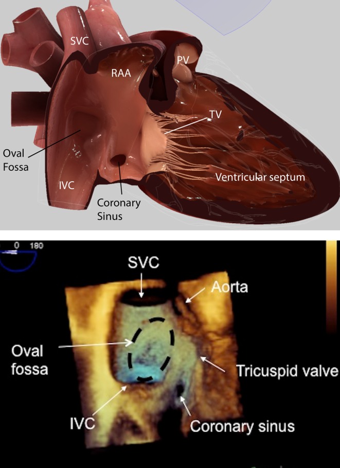
(A) HeartWorks TOE simulator image at 0° mid-oesophageal level showing the atrial septum from the right atrial side. IVC, inferior vena cava; PV, pulmonary valve; RAA, right atrial appendage, SVC, superior vena cava; TV, tricuspid valve. (B) 3D TOE image at 0° mid-oesophageal level showing the atrial septum and from the right atrial side and the adjacent cardiac structures. IVC, inferior vena cava; SVC, superior vena cava.
Atrial septal defects unsuitable for device closure
Several types of defects are generally regarded as unsuitable for device closure (Fig. 2A and B). Device closure requires ‘rims’ of tissue surrounding the defects to which the closure device can grip to attain a stable, permanent position within the atrial septum.
Figure 2.
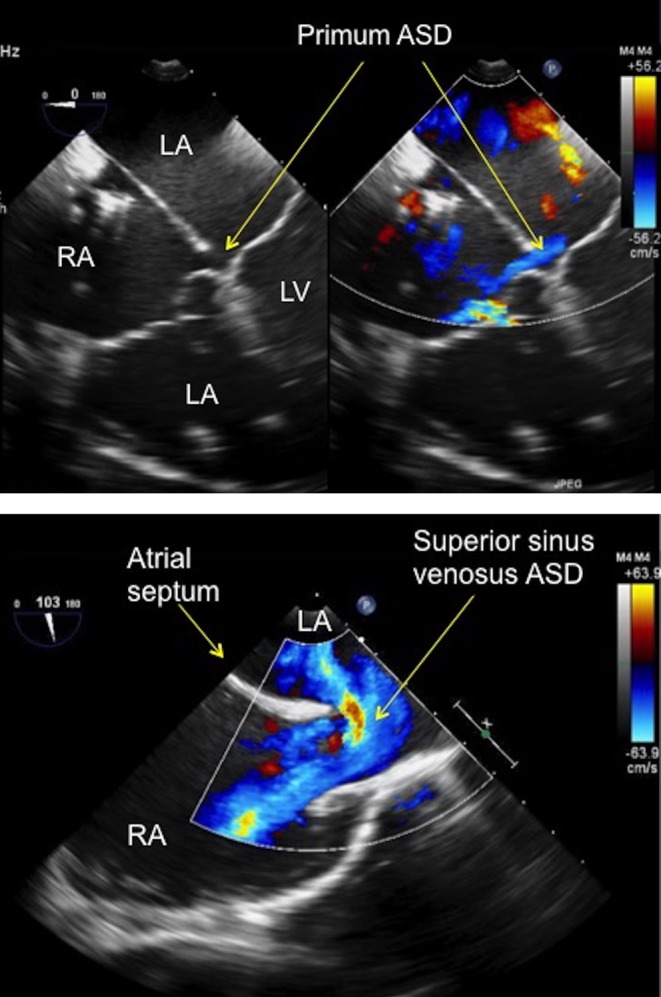
(A) TOE image at 0° mid-oesophageal level four-chamber view showing a small primum atrial septal defect (see arrows) in a patient with a partial atrioventricular septal defect. The defect has no rim to the atrioventricular valve, which precludes percutaneous device closure. ASD, atrial septal defect; LA, left atrium; LV, left ventricle; RA, right atrium; RV, right ventricle. (B) TOE image at 100°, high oesophageal level showing a large superior sinus venosus atrial septal defect with left to right shunt seen on colour Doppler. Note that there is no rim to the superior vena cava. ASD, atrial septum; LA, left atrium; RA, right atrium.
Atrioventricular septal defect
The AVSD is characterised by a common AV junction. There is variability as to the size and presence of the atrial and ventricular components of the defect. An AVSD without a ventricular component, sometimes termed ‘partial’ AVSD or ‘ostium primum’ atrial septal defect. Whatever name is applied, one of the borders of the atrial communication is made up of the inferior and superior bridging leaflets themselves without any rim which precludes device closure (Fig. 2A). This type of defect is repaired surgically using patches to close the atrial and ventricular component (if present) accompanied by repair of the left atrioventricular (AV) valve.
Sinus venosus defects
The superior sinus venosus ASD is located at the junction between the SVC and atrial septum with the SVC typically ‘overriding’ the upper margin of the atrial septum (Fig. 2B). There is no tissue rim between the SVC and the atrial septum, thus precluding device closure. This defect has the added complication of being associated with anomalous drainage of the right pulmonary veins (most commonly the right upper pulmonary vein). The inferior sinus venosus ASD is located at the junction between the IVC and atrial septum. There is no IVC tissue rim for the device to grip onto, which would therefore seriously affect the stability of a device if it was deployed.
Considerations regarding selection for device closure are outlined in Video 1.
Assessment of atrial septal defects for device closure. Pre-procedural assessment: anatomy of the atrial septum and defects unsuitable for device closure. View Video 1 at http://movie-usa.glencoesoftware.com/video/10.1530/ERP-18-0007/video-1.
Download Video 1 (453.6MB, mp4)
Secundum atrial septal defects: suitability for device closure
The echocardiographic approach to case selection for ASD closure is better conveyed in moving images rather than still images (Video 1). In the assessment of secundum ASDs, adequacy of the ‘rims’ of the defect is a core consideration. The ‘rims’ refer to the tissue between the defect and key adjacent anatomic structures. Some prefer to name the rims according to orientation e.g. antero-superior, posterior, but our preference is to name the rims according to the closest adjacent anatomic structure, namely the IVC, SVC, coronary sinus, mitral valve, right pulmonary veins and the aortic valve. The necessary size of rims is impacted by the size and type of septal occluder, which will be deployed. The majority of septal occluders are based on a model of two discs joined by a waist. As the size of the device increases, the necessary rim size is also larger.
A complete absence of the IVC rim is viewed as a contraindication by most operators. More controversial is the significance of absence of the aortic rim. A small, or even absent rim to the aorta is common in around 30–40% of secundum defects. Most operators do not regard absence of an aortic rim as a contraindication to device closure. Most view it as acceptable for devices to splay over the aorta provided the aorta is not indented by the device, thus negating the need for a tissue rim.
The assessment of ASDs can be made by transthoracic echocardiography, and some groups have even used this to guide closure procedures, but the latter is not used in our centre. If the image quality is good, it can be of adequate diagnostic quality to triage to surgery or the catheter lab. The ASD is best defined from a combination of long and short axis subcostal views. However, as children get older and the abdomen becomes firmer, the necessary data set to fully evaluate the defect in relation to all the surrounding cardiac structures can be quite difficult to acquire. For this reason, a transoesophageal echocardiographic assessment is often necessary, particularly in older children and adults.
Pre-procedural transoesophageal echocardiographic (TOE) assessment of secundum ASDs
Utilising a structured, systematic approach (using a series of advance/withdraw movements and rotation of the TOE probe), the defect can be fully evaluated with 2D, 3D and colour Doppler with respect to the:
Size and position of the defect
Size and quality of the tissue rims
Presence of additional defects and their position within the septum
Presence of any additional lesions, which may affect the decision to go down a surgical or percutaneous closure route
The transducer angles described below are widely accepted as the standard TOE positions to visualise the relationship between the ASD and the surrounding cardiac structures. However, the angles described below may vary slightly between patients to obtain the optimal images.
Procedural imaging is covered in Video 2. This includes step by step video guidance.
Assessment of atrial septal defects for device closure. Procedural assessment: evaluating the defect prior to closure and imaging for device closure. View Video 2 at http://movie-usa.glencoesoftware.com/video/10.1530/ERP-18-0007/video-2.
Download Video 2 (1.5GB, mp4)
Patient anatomy
Zero degrees
The starting point for assessment of any ASD should begin at 0°.
The mid-oesophageal (M-E), 0° view produces a four-chamber view of the heart, delineating the relationship between the ventricles and the atria. This allows for the qualitative assessment of the ventricular function, relative ventricular and atrial sizes and the AV valves prior to assessing the defect. Significant right heart dilatation alerts the echocardiographer to a potentially large atrial septal defect (Fig. 3).
Figure 3.
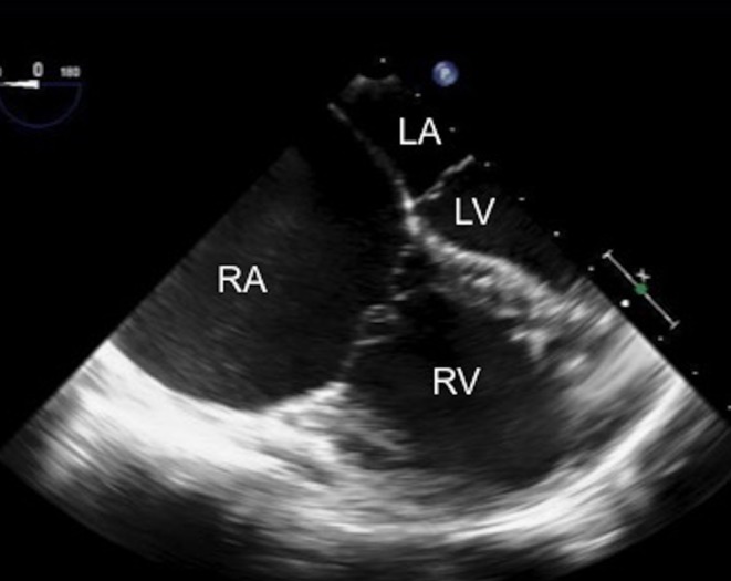
TOE image at 0°, mid-oesophageal level four-chamber view showing the dilatation of the right heart chambers, in particular the right atrium in comparison with the left heart chambers. LA, left atrium; LV, left ventricle; RA, right atrium; RV, right ventricle.
In the four-chamber view (4CV), careful assessment of the amount of mitral and tricuspid regurgitation should be made with colour flow Doppler. Using advance and withdraw movements of the probe, the maximum amount of regurgitation can be seen. Doppler assessment of tricuspid valve regurgitation should be performed to quantify the right ventricular (RV) systolic pressure. (It is worth noting that this may be reduced from pre-procedure imaging if the patient is having the TOE under general anaesthesia). The mitral rim can be seen in the 4CV and should be measured. The size of the mitral rim has implications for device closure. Depending upon the device manufacturer, a minimum rim length will be specified for safe device seating (Fig. 4). The length of the atrial septum can also be measured in this view, although some prefer a transgastric view for this measurement. This length is important, especially in paediatric patients with large defects and relatively small atria as the left atrium (LA) disc of the device selected for closure should not exceed the septal length.
Figure 4.
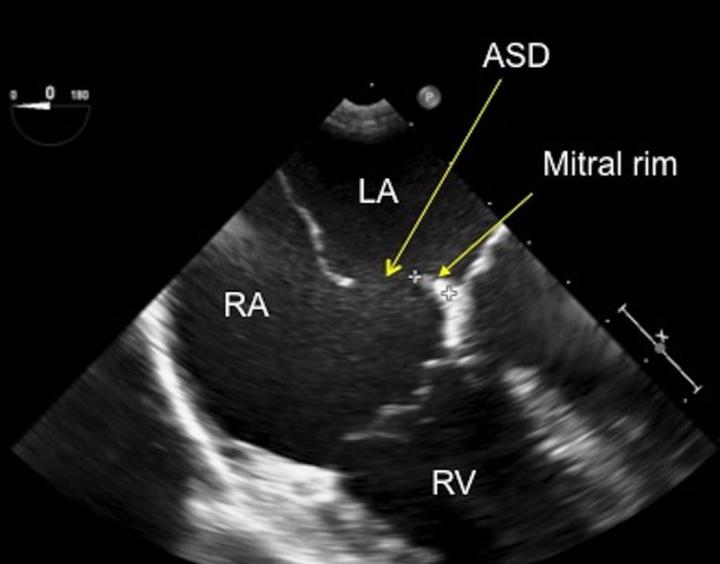
TOE image at 0°, mid-oesophageal level showing a small secundum atrial septal defect with a small rim to the mitral valve, which measures 6.8 mm. ASD, atrial septal defect; LA, left atrium; RA, right atrium; RV, right atrium.
Once these initial images have been recorded, the probe can be turned clockwise to bring the atrial septum into view. Using small clockwise and anticlockwise movements, the septum can be interrogated with 2D and colour flow Doppler to bring the defect into view (Fig. 5). A long sweep then needs to be performed with colour flow Doppler from a high oesophageal level to low oesophageal level, to assess the entire length of the septum in the 0° plane. The septum will be visualised from the superior vena cava (SVC) most superiorly until the coronary sinus, most inferiorly, comes into view. This will show the position and the extent of the defect. It may also show additional defects, if they are present.
Figure 5.
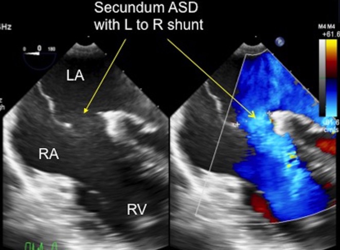
TOE image at 0°, mid-oesophageal level showing the secundum ASD shunting left to right from the left atrium to the right atrium, as demonstrated by the arrows. LA, left atrium; RA, right atrium; RV, right ventricle.
The ASD then needs to be measured where it appears the largest, measuring the firm edge to firm edge of the tissue (Fig. 6). Take note of the quality of the septal tissue whilst assessing the ASD as the tissue rims can have different characteristics. It can be thin and floppy, aneurysmal or very thick. Thin, floppy tissue should be thoroughly investigated for fenestrations and small additional defects. A description of the rim tissue quality is important (Fig. 7) because thin and floppy may not anchor a device well. This information should be communicated with the interventionalist. Furthermore, some patients have prominent Eustachian valve tissue on the right side of the atrial septum. This can interfere with catheter position and device placement and should be noted and communicated.
Figure 6.
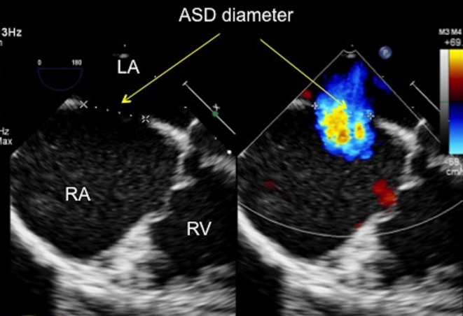
TOE image at 0°, mid-oesophageal level showing the atrial septal defect with both 2D imaging and colour Doppler. The defect measures 14.7 mm on 2D (firm edge to firm edge) and 13 mm with colour Doppler. ASD, atrial septal defect; LA, left atrium; RA, right atrium; RV, right ventricle.
Figure 7.
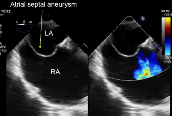
TOE image at 0° at mid-oesophageal level showing a thin, aneurysmal atrial septum, bowing into the dilated right atrium. LA, left atrium; RA, right atrium.
Next, confirm both the right pulmonary veins enter the left atrium. The right upper pulmonary vein (RUPV) inserts closest to the atrial septum (Fig. 8), passing posterior to the SVC. Sometimes a degree of flexion of probe is needed to bring the right veins into view, especially the right lower pulmonary vein (RLPV). Perform a sweep with colour Doppler that shows the right veins definitively entering the LA. Measure the rim between the RUPV and the defect (Fig. 9). For completeness, turn the probe clockwise to confirm that the left pulmonary veins enter the left atrium with colour flow Doppler, but these are very unlikely to be anomalous in this setting. The left atrial appendage (LAA) will also be seen in this view with the left upper pulmonary vein (LUPV) adjacent. Some anticlockwise adjustment of the probe will bring the LLPV into view. Often, the LAA can be better seen with a rotation of the transducer to 30° or more. Take note of where the best image of the LAA and the LUPV is obtained as this view will be required later in the scan for device deployment.
Figure 8.
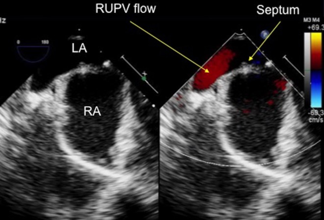
TOE image at 0° at high oesophageal level confirming that the right upper pulmonary vein enters the left atrium, adjacent to the atrial septum. LA, left atrium; RA, right atrium; RUPV, right upper pulmonary vein.
Figure 9.
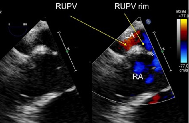
TOE image at 0°, high oesophageal level showing the measurement of the rim to the right upper pulmonary vein and the atrial septal defect, which measures 8.6 mm. LA, left atrium; RA, right atrium; RUPV, right upper pulmonary vein.
30 degrees
At 30°, the aorta in a short axis projection comes into view. This is the first view where the aortic rim can begin to be appreciated (Fig. 10). Interrogate the entire septum from superior to inferior with a long withdraw/advance movement of the probe, utilising both 2D and colour flow Doppler (Fig. 11), similar to the sweep performed at 0°. This will allow for assessment of the aortic rim and additional defects, if present, that may now become apparent at this angulation, especially towards the roof of the atriums.
Figure 10.
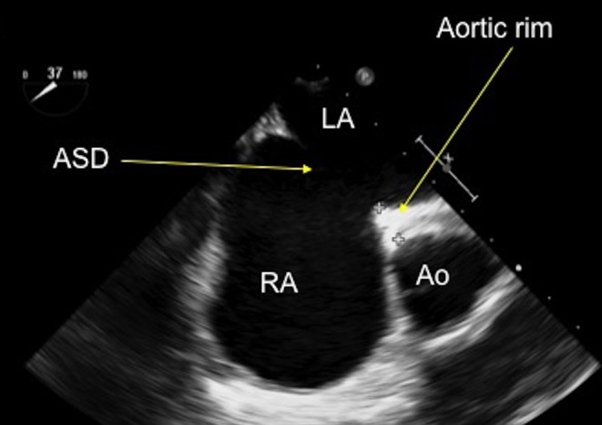
TOE image at 30°, mid-oesophageal level showing an anteriorly positioned secundum atrial septal defect with a small rim to the aorta. Ao, aorta; ASD, atrial septal defect; LA, left atrium; RA, right atrium.
Figure 11.
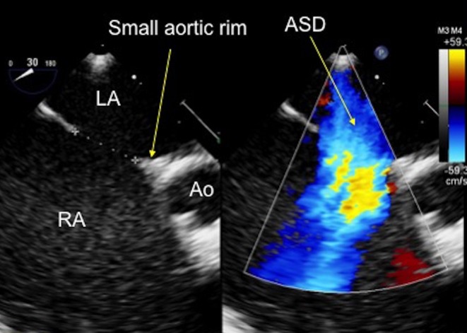
TOE image at 30°, mid-oesophageal level showing an anteriorly positioned secundum atrial septal defect with a small aortic rim, which measures 9 mm. Ao, aorta; ASD, atrial septal defect; LA, left atrium; RA, right atrium.
The aortic rim may appear small or deficient at some points within the sweep and larger at other points, indicating that the aortic rim maybe only partially deficient. Freeze and measure the aortic rim, if present, including where the rim appears most deficient. Measure the defect size where it is the largest. Record and communicate any floppy tissue rims and any additional defects, if present.
45 degrees
Further rotation of the transducer through to 45° allows the defect to be seen more in relation to the aorta. At 45°, the aorta is completely in short axis in a true en face projection, with all three cusps seen clearly. The septum should be interrogated again with 2D and colour Doppler. A long sweep from superior to inferior should be performed with both 2D and colour Doppler (or a colour compare or simultaneous mode) to fully assess the extent of the aortic rim and the size of the defect. The defect should be measured at the point where the diameter is the largest. Any additional defects that come into view in this plane should be interrogated fully to assess their size, extent and proximity to the main defect (Fig. 12).
Figure 12.
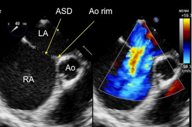
TOE image at 45° mid-oesophageal level showing a small- to moderate-sized secundum atrial septal defect which measures 12.9 mm on 2D imaging and 15.7 mm diameter when measured with colour Doppler on the image. There is a small aortic rim which measures 3.47 mm. Ao, aorta; ASD, atrial septal defect; LA, left atrium; RA, right atrium.
60 degrees
Further rotation of the transducer through to 60° continues to show the relationship between the aorta and the septum. A similar approach should be adopted to that described at 30° and 45°. The 60° view also shows the entire right heart, if the probe is turned anticlockwise and the depth is increased. This is an excellent view to assess the tricuspid valve, the RV, the RVOT and the pulmonary valve.
90–110 degrees
Rotation of the transducer to 90–110° produces the bi-caval view (Fig. 13), where the septum is seen extending between the SVC and the IVC. The exact angle varies between individuals. Careful sweeping up and down the septum by advancing and withdrawing of the probe and turning the probe slightly clockwise and anticlockwise will best define the position of the defect(s) within the septum. The defect rims to the SVC and the IVC can be measured in these views. Withdrawing the probe slightly will bring the SVC rim and superior structures such as the RUPV into view. Often the transducer will need to be rotated to up to 110° to see the SVC and the rim to the defect clearly. The SVC rim can then be measured (Fig. 14). The RUPV can also be seen in this plane turning by the probe clockwise slightly. This is an excellent view for confirming the right pulmonary venous drainage to the LA, especially if this has been difficult to see clearly from the 0° view.
Figure 13.
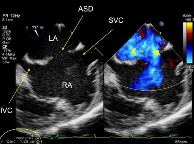
TOE image at 120° at mid-oesophageal level showing a central secundum atrial septal defect with sufficient rims to the inferior and superior vena cavae for a septal occluder device. ASD, atrial septal defect; LA, left atrium; IVC, inferior vena cava; RA, right atrium; SVC, superior vena cava.
Figure 14.
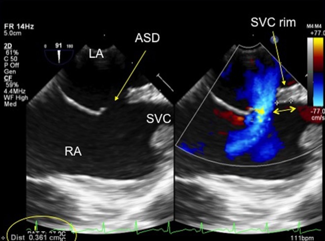
TOE image at 90° high oesophageal level showing the position of the secundum defect in relation to the superior vena cava. There is a small rim to the superior vena cava which measures 3.61 mm (see double-ended arrow). ASD, atrial septal defect; LA, left atrium; RA, right atrium; SVC, superior vena cava.
Advancing the probe further will bring inferior structures more into view, such as the IVC and the Eustachian valve. The IVC rim to the defect can also be measured in this view. The bicaval view is very useful for visualising any additional defects that maybe present, especially inferiorly, by making advance/withdraw movements and subtle turning of the probe allow the full length of the septum to be visualised. Additional defects or fenestrations can be identified with colour Doppler. Their position, diameter and distance from the main defect must be discussed with the interventionalist.
Notes on imaging the inferior rim
The inferior rim of the atrial septal defect is notoriously difficult to visualise. In smaller children, this may be better appreciated by transthoracic echocardiography than TOE. On TOE, the rim may be seen best visualised somewhere between 70° and 90° with the probe withdrawn more inferiorly. An alternative is to use a transgastric approach with heavy flexion of the probe at an angle of around 90–120°. It is especially important to interrogate the inferior rim well as this is often the most difficult tissue rim to clearly see and where additional small defects can easily be missed. Absence of this rim is viewed by most as a contraindication to device placement because of the risk of device embolization.
150 degrees
This is an additional view that is sometimes helpful for further investigation of the mitral rim and the relationship of the defect to inferior structures, such as the coronary sinus.
Added value of 3D echocardiography
In recent years, TOE probes have been developed, which permit both 2D and 3D imaging. Current manufacturer recommendations are that the 3D probe is suitable for patients >30 kg but many operators will use this approach in patients down to 25 kg. 3D echocardiography permits visualization of the atrial septum en face either from the right or the left atrial side. The position, size and number of defects may be appreciated intuitively as well as the adjacency to other structures such as the aorta and atrioventricular valves (3). The 3D modalities used vary according to operator and institutional preference. Acquisition of a full volume of data over several cardiac cycles optimises spatial resolution, temporal resolution and field of view but has the disadvantage of requiring post-processing.
Live 3D modalities do not take a great deal of additional time to acquire, especially if an x-plane (two orthogonal planes visualised simultaneously), a 3D zoom or a 3D live image is acquired as they require no cropping to measure the ASD. This is of practical importance during a closure case, when constant live imaging is a necessity. 3D zoom images are straightforward to anatomically orientate to quickly appreciate the appearance of the defect en face. The 3D views obtained should then confirm the size and position of the defect (or defects) within the septum with respect to the 2D views (Fig. 15).
Figure 15.
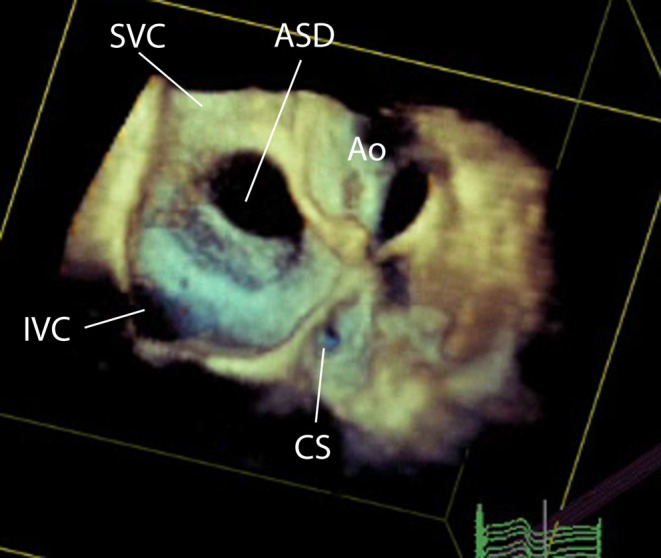
3D TOE image at mid-oesophageal level, viewed from the right atrial aspect showing a large central secundum atrial septal defect.
More detailed information regarding 3D echocardiography in congenital heart disease and the imaging of atrial septal defects can be obtained from the recently published joint European and north American guidelines (4). This is particularly beneficial when there are multiple or fenestrated defects (Fig. 16). It allows the defect size as well as the distance between the defects to be measured. During a closure case imaging with live 3D is particularly useful if there are multiple defects, both for visualization of defects and also wires and catheters. It is much easier to visualise which defect the catheter is across than with 2D imaging. For example, to confirm the catheter is across the central defect if occlusion of the entire oval fossa is being considered to close multiple defects with a single device (Fig. 17). Lastly, the technique has been advocated for closure of residual defects when other occlusion devices are in situ, which is described elsewhere (5).
Figure 16.
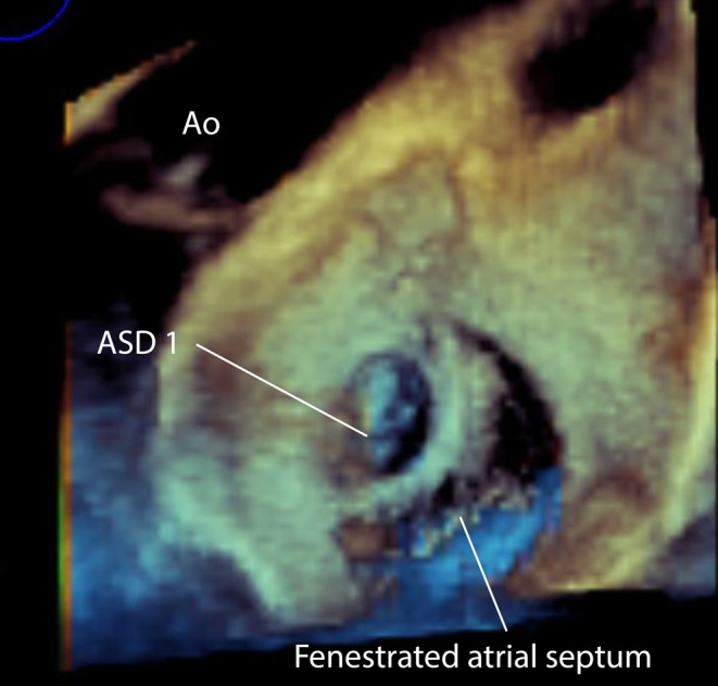
3D TOE image at mid-oesophageal level viewed from the left atrial aspect showing a small superior secundum atrial septal defect and a larger mutlifenestrated atrial septal defect. This has implications for the planning of device closure as two devices may be required to close the defects. ASD, atrial septal defect.
Figure 17.
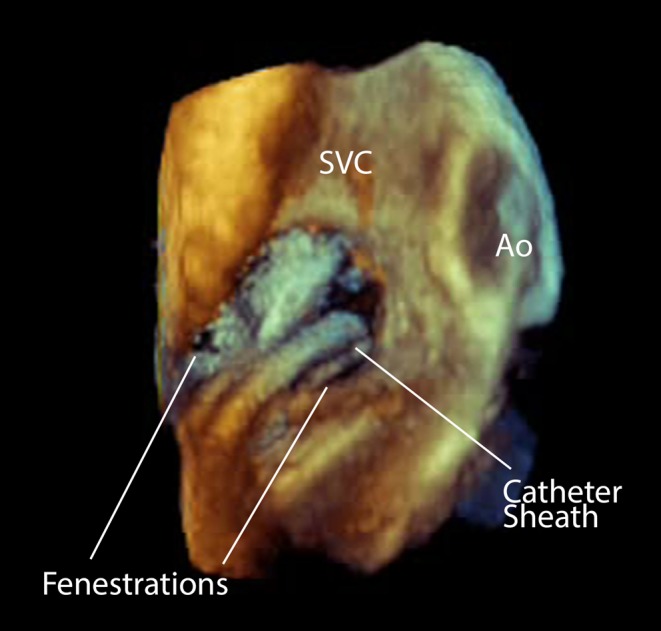
3D Image of a catheter sheath crossing a fenestrated atrial septal defect. This view is from the right atrial aspect. Ao, aorta; SVC, Superior vena cava.
Possible pitfalls when imaging atrial septal defects
Confusion of the Eustachian valve with the septum
The Eustachian valve is the primitive valve of the IVC, located at the junction between the IVC and the RA. In fetal life, it is used to direct the most oxygenated blood from the ductus venous across the foramen ovale from the right atrium to the left atrium. This function ceases after birth. The Eustachian valve usually regresses after birth, but it may persist into adult life with an appearance that varies greatly from patient to patient. The appearance on echocardiography can range from a thin, filamentous, hypermobile strand to a thicker, more immobile ridge of tissue. It may cross the atrial septum and insert into the embryonic valve of the coronary sinus or it may appear to end mid-RA or at the IVC/RA junction. Confusingly, it may mimic the atrial septum. Care should be taken to distinguish between the atrial septum and the Eustachian valve so that the gap between the Eustachian valve and the atrial septum is not interpreted as the ASD.
On TOE, the Eustachian valve is best seen on the 0° and the 90° bicaval view. It is always attached to the IVC/RA junction, but at the anterior margin of the IVC in contrast to the atrial septum (Fig. 18). Helpfully, the Eustachian valve is often seen at an angle to the slightly curved atrial septum.
Figure 18.
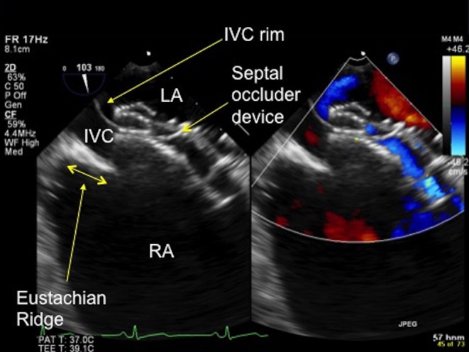
TOE image at 100° low oesophageal view showing a prominent Eustachian ridge (see double-ended arrow), which has the potential to be confused with the IVC rim. In this image the IVC rim has been well caught by the septal occluder device. IVC, inferior vena cava; LA, left atrium; RA, right atrium.
Presence of a ‘spiral septum’
A more unusual variant is the presence of a spiral or ‘double’ atrial septum. In this case, there is an unusual attachment of the septum primum to the roof of the LA, which produces a separation of the secundum and primum septums, in addition to the atrial septal defect. This is not an absolute contraindication to device closure, but careful imaging and device size selection is required to ensure that all rims are safely captured within the device prior to the device release (6).
Important practical notes on procedural imaging
The atrial septum should be assessed thoroughly prior to intervention with the systematic approach described earlier. The septum is initially imaged at 0° and then gradually through the key angles to around 150° to visualise the defect and its relation to other adjacent cardiac structures (or additional defects) from all angles. Good communication between the echocardiographer and the interventionalist is vital so that the interpretation of images is communicated and any concerns are discussed to allow them to be addressed promptly at every stage of the procedure. Occasionally, it may rapidly become obvious that a defect is unsuitable for closure, such as very large defects or those with anomalous pulmonary veins. This should be discussed with the interventionalist as soon as it becomes apparent.
When performing the TOE, it is very important not to place the entire focus on visualising the most obvious defect. There are often additional, smaller defects in association with a larger defect, and it is equally important to visualise and fully evaluate these additional defects. Additional defects have implications for planning the closure approach. For example, what is the distance between the two defects? Can both the defects be closed with a single device or will multiple devices be required? 3D imaging, as discussed earlier, is very useful for planning the closure approach in such cases (Fig. 19).
Figure 19.
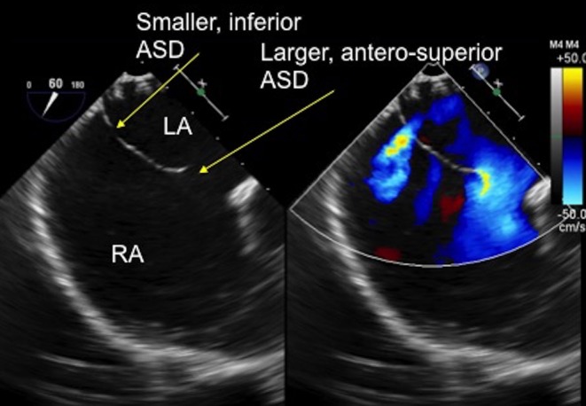
TOE image at 60° mid-oesophageal level showing two separate defects in the thin atrial septal tissue. There is a larger, antero-superior defect with a small aortic rim and a smaller, more inferior defect which are clearly seen with the colour Doppler. ASD, atrial septal defect; LA, left atrium; RA, right atrium.
Optimal echocardiographic imaging of the ASD closure procedure
A video of the ASD closure procedure is available to download to accompany this review. A transducer rotational angle between 30° and 60° is the optimal position for assessing the defect and the closure process, from crossing the defect with a guidewire, assessing catheter position to releasing the closure device. At this angle, the defect, the atriums, the left pulmonary veins and the LAA are clearly visualised. In addition, the orientation of the device closure discs to the atrial septum are optimally visualised as the device is opposed to the atrial septum. Some units employ systems, which aim to enhance navigation by integrating echocardiographic and fluoroscopic images, but this is not currently used at our centre.
Crossing the defect with a guidewire
The guidewire can be seen advancing from the RA across the septum into the LA well in this view (Fig. 20). Crossing is easier in larger defects than small defects or patent foramen ovale. In smaller defects, it can be helpful to tell the interventionalist their position in relation to the defect to aid crossing. Alternating between a 30–60° and a 90–110° view can be helpful as well, for example, to see if the guidewire repeatedly extends into the SVC rather than crossing the defect.
Figure 20.
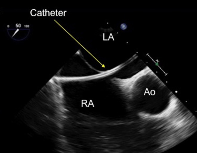
TOE image at 50° mid-oesophageal view with a catheter seen clearly crossing the defect and advanced into the mid-left atrium. Ao, aorta; LA, left atrium; RA, right atrium.
Balloon sizing
If the interventionalist decides to balloon size the defect, 30–50° is an excellent position to assess the balloon sizing process. The balloon will be seen as it is advanced over the guidewire and into the LA. This angle is helpful for assessing the position of the balloon between the atriums and the measurement of the balloon waist. The balloon waist will be well seen, although the rotation of the probe may need to be adjusted slightly to best image the waist.
A stop-flow technique should be employed to avoid oversizing the defect. The inflation of the balloon should be imaged in colour Doppler mode. Once there is no longer any flow through the defect, and it is totally occluded by the balloon this information should be communicated with the interventionalist and balloon inflation should stop. The waist diameter should then be recorded (Fig. 21). Excessive inflation of the balloon may stretch the defect and lead to a larger than necessary device being selected.
Figure 21.
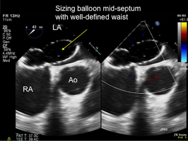
TOE image at 80° mid-oesophageal level showing the sizing balloon inflated across the defect and the ‘stop-flow’ point being reached. The balloon is inflated sufficiently such that it completely occludes the atrial septal defect and there is no flow is seen between the balloon and the defect. The waist of the balloon is then measured at this point and used to select the optimal device size to occlude the defect. Ao, aorta; LA, left atrium; RA, right atrium.
Advancement of delivery sheath
The advancement of the delivery sheath over the guidewire and into the LA can be well seen in this view (Fig. 22). The delivery sheath can be distinguished from the guidewire as it is a broader structure with a larger, echo-lucent lumen, designed for the device to pass through
Careful attention should be paid to the position of the delivery sheath in the LA. It should be advanced into the LUPV and not into the adjacent LA appendage. This can be imaged by some clockwise turning of the probe to follow the sheath from where it crosses the defect to the LUPV/LAA junction.
Figure 22.
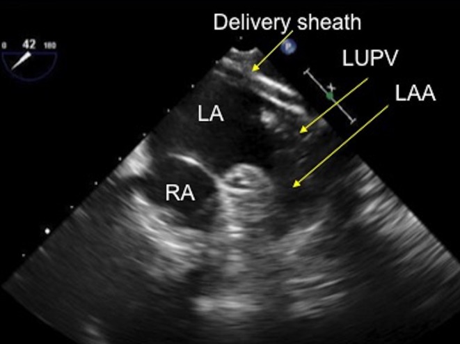
TOE image at 40° mid-oesophageal level showing the delivery sheath positioned in the left upper pulmonary vein, adjacent to the left atrial appendage. LUPV, left upper pulmonary vein; RA, right atrium.
Disc release
From this position in the LUPV, the left disc release can be seen as it released from the delivery sheath at the LUPV/LA junction. Some anticlockwise turning of the probe will allow the visualization of the device and the sheath as it is all pulled through the LA towards the atrial septum
This is a very good view to assess the position of the left disc in relation to the aorta and the atrial septum. The LA disc should approach the septum at a slight angle to seat at the aortic rim and then flatten to be flush with the septum as it is pulled towards the septum. Good communication with the operator is imperative at this time. If the disc position is sub-optimal, the interventionalist can re-capture the LA disc and try again to get a better position.
Once the left disc is in a good position, the right disc will then be released and advanced to the septum, simultaneously capturing the defect rims. Some small turning movements of the TOE probe at this point will allow the capture of the rims at either margin of the device to be well seen (Fig. 23).
Colour flow Doppler is very useful at this point to assess for any shunt that is outside the device, which should be immediately communicated. This may indicate that the device needs to be re-positioned or is too small for the defect. It should be noted that flow through the device is a completely normal finding. As the device endothelializes with time this flow will cease.
Figure 23.
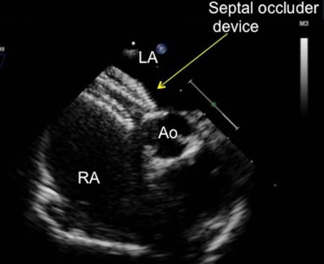
TOE image at 10° mid-oesophageal level showing a septal occluder device with a desirable flat profile abutting the aorta. The left atrial and right atrial discs are on their correct sides of the septum, with the tissue of the aortic rim well caught between the discs. Ao, aorta, LA, left atrium; RA, right atrium.
Checking the device
Once the device appears well seated, it should be assessed in all the views from 0° to 150° to allow for complete assessment of the position, rim capture and device configuration. In particular:
0 degrees
-
Assess the rim to the RUPV
Is the device close to the RUPV/LA junction?
Is flow in the RUPV turbulent or impeded in any way?
Is there any residual shunt around the device?
-
Assess the rim to the mitral valve
Is there a good distance between the device and the annulus of the anterior leaflet of the mitral valve? (This can also be seen well from the 90° view, when the probe is turned clockwise to see the device en face and the movement of the mitral valve in relation to the device). The finding of mitral valve regurgitation, which was not present before closure should cause concern that the device is impinging on the mitral valve.
45 degrees
Is the device well seated around the aortic rim?
Is there residual shunt seen around the aortic rim with colour Doppler?
90 degrees
-
Assess the device position in relation to the SVC and IVC rims (Figs 24 and 25)
Are the rims well-captured i.e. do they appear ‘sandwiched’ between the two discs?
Is there any residual shunt?
Is the flow laminar in the SVC and the IVC? Is the flow impeded in any way by the position of the device? You will need to withdraw the probe slightly to see the SVC and advance slightly into the patient to visualise the IVC well
Figure 24.
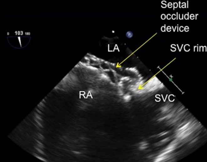
TOE image at 100° high oesophageal view showing the superior vena rim of the atrial septal defect well caught by the superior limb of the atrial septal defect occluder with the left and right sided discs successfully capturing the superior vena cava tissue. LA, left atrium; RA, right atrium; SVC, superior vena cava.
Figure 25.
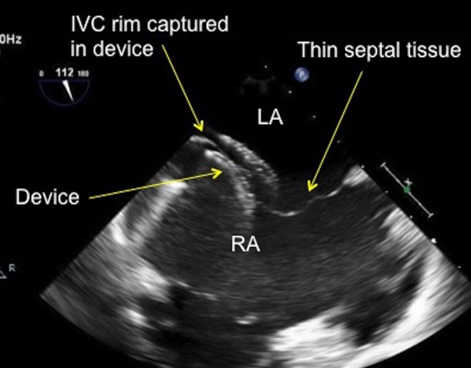
TOE image at 110° low oesophageal view showing the inferior vena cava rim of the atrial septal defect being well caught by the inferior limb of the atrial septal defect occluder with the left and right sided discs successfully capturing the thin inferior vena cava tissue rim. IVC, inferior vena cava; LA, left atrium; RA, right atrium.
150 degrees
Check the position of the device in relation to the coronary sinus and the mitral valve
In all the views, check the septum for any additional defects in the septum that is not covered by the closure device. These may have become ‘unmasked’ by the closure of the main defect and may now present themselves as the flow within the atria has been changed.
How will I know if the device is in a bad position?
There are several ways to know if the device is in a sub-optimal position and will need to be recaptured and redeployed.
In the 30–60° view, when deploying the device, the LA disc should not approach the septum at an acute angle. If the LA disc is too angled towards the aorta as it is pulled towards the septum, it is more likely to pull through the defect, especially if there is a deficient aortic rim. If the disc does pull through, the interventionalist will need to re-capture the LA disc and try again to get a better position (Fig. 26).
Figure 26.
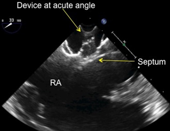
TOE image at 30° mid-oesophageal view showing the septal occluder device at an acute, almost 90° angle as it approaches the atrial septum. RA, right atrium.
It is good practice to communicate the position of the disc early with the interventionalist. If the angle of deployment appears too acute as it approaches the septum, early communication allows the interventionalist to adjust the device angle, which is preferable to having the device pull through the defect and have to be recaptured. This becomes important if there are repeated difficulties in positioning the left disc and the disk is repeatedly recaptured, potential affecting the integrity of the delivery sheath or the LA disc configuration.
Once both discs are in position against the septum, they should appear linear and sit flat to the septum. The discs should not appear bulky or appear to stand some distance from the septum nor should they move excessively within the heart. If this is the case, the device should be assessed from the angles as described above and be re-positioned, if necessary. The position of the device with respect to the mitral valve anterior leaflet needs to be carefully assessed when the device is being positioned. If the device appears to impinge upon the anterior leaflet of the mitral valve and there is an increase in the amount of mitral regurgitation from the initial imaging, this may be an indication to not deploy the device (Fig. 27). Again, good communication is imperative between the echocardiographer and the interventionalist. Lastly, a residual leak seen between the device and the septal tissue with colour Doppler may indicate that the device is not well seated or is not the correct size to occlude the defect (Fig. 28). This should be communicated with the interventionalist and the decision taken to re-position the device or remove the device and try again with a larger one.
Figure 27.
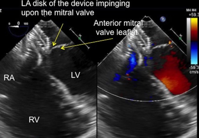
TOE image at 0° mid-oesophageal view showing the position of the left atrial disc of the septal occluder, which is indenting the anterior leaflet of the mitral valve in systole (see position of arrows). LA, left ventricle; LA left atrium; RA, right atrium; RV, right ventricle.
Figure 28.
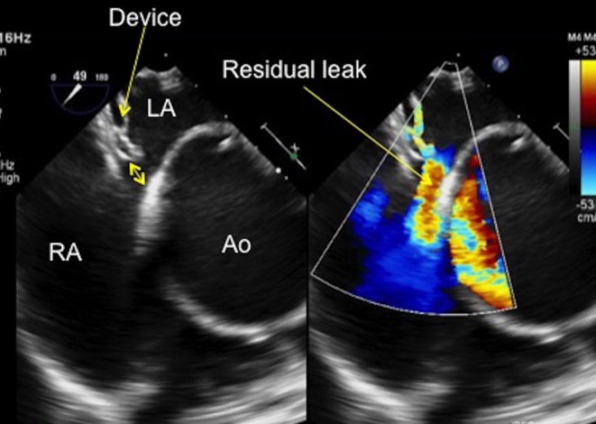
TOE image at 50° mid-oesophageal view showing a residual leak at the aortic end of the septal occluder device. The gap between the device and the aorta can be clearly seen on two dimensional imaging and the residual left to right shunt is well demonstrated with colour Doppler (see arrow). Note the very dilated aortic root in this patient. Ao, aorta; LA, left atrium; RA, right atrium.
How do I image for potential device erosion?
Device erosion is a very rare, but potentially catastrophic complication of ASD device occlusion (7). Device erosion usually occurs early after the closure procedure (within the first 72 h after device implantation), but some cases have been reported up to 1 year following the procedure (7).
Device erosion has been identified as a potential problem where the following risk factors are present:
A deficient aortic rim
A deficient superior rim (rim to the SVC, which would bring the device in contact with the atrial roof)
Excessive movement of the device within the heart, which is usually associated with a dynamic ASD (one that changes size significantly during the cardiac cycle) (8)
Deployment of a large, potentially oversized, device
However, many ASDs have these features, especially deficient aortic and small superior rims. Careful assessment of these rims needs to be made and communicated with the interventionalist, especially if they are deficient. Devices that appear to indent or pinch the aortic root when the aortic rim is deficient should be redeployed or removed altogether and a smaller device used.
There must be a collaborative approach between the echocardiographer and the interventionalist in terms of device size selection. This ensures that the correct sized device is chosen for the defect size. For example, if the stop-flow technique is not employed when balloon sizing, further inflation of the balloon until the waist cannot be made any larger may lead to oversizing the defect and thus oversizing the device.
In terms of imaging, a 30–60° view will best assess the position of the device with respect to the aorta. The SVC rim and atrial roof are best seen from 0° and 90–110°. Once the device is in place, a 3D view of the device at between 0° and 30° tilted up to show the device and the roof of the atria can also help identify if the outer edge of the device is impinging upon the roof of the atria during certain parts of the cardiac cycle (Fig. 29).
Figure 29.
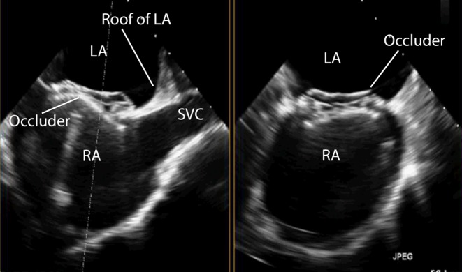
TOE image at 110° high oesophageal view showing the position of the device in relation to the roof of the left atrium and the SVC. The device in this example is positioned well away from the left atrial roof. LA, left atrium; RA, right atrium; SVC, superior vena cava.
Visualising the ‘wiggle’
Once the above steps have been performed and both the echocardiographer and the interventionalist are satisfied with the device position, the ‘wiggle’ can be performed. The ‘wiggle’ is a standard device stability test for double-disc ASD occluders, but is less suitable for other types of device with a different configuration such as a spiral. This manoeuvre requires the interventionalist firmly pulling on the device delivery cable to test the stability of the device and how well seated the device is within the septum. The right disc will move away from the septum and the left disc will be forced further towards the septum, to check it does not pull through the defect. The right disc will then be pushed up to the septum to test that the device will not push through to the LA. The wiggle is best imaged from the 45° to 60° view so that both discs can be seen in cross section with the septum between the two discs. A long loop should be recorded that shows the entire wiggle from the right disc moving away from the septum to being pushed up against it.
If the device fails the wiggle and pulls through the defect it needs to be recaptured in the delivery sheath and the above imaging and device delivery process repeated.
Device release
If the device passes the wiggle test it can be released. A loop of the device release should be recorded. The device can move position as the torque on the device is released by the removal of the delivery cable. The amount of the movement of the device varies with the device vendor.
Imaging after device release
Once the device is released the imaging steps from 0° to 150° should be repeated to check the device position. It is highly unlikely that the small movement of the device on release from the delivery cable will adversely affect the device position, but this should be excluded. The approach to assessment following closure of the ASD is shown in Video 3.
Assessment of atrial septal defects for device closure. Post-procedural assessment in the catheter lab. View Video 3 at http://movie-usa.glencoesoftware.com/video/10.1530/ERP-18-0007/video-3.
Download Video 3 (367.5MB, mp4)
The amount of mitral and tricuspid regurgitation should also be assessed to see if this has increased post device release. This is best done at 0°.
Lastly, whilst at 0° the presence of a pericardial effusion should evaluated. Increase the depth of the image so that the whole heart can be seen. Turning the probe slightly clockwise and anticlockwise will show the border between the right and left heart and the pericardium. Any abnormal findings should be communicated immediately to the interventionalist.
Imaging post procedure
All patients require a transthoracic echo prior to discharge to assess for any potential complications, including device embolization and pericardial effusions. This is usually performed 24 h after the procedure. Careful attention should be paid to the position of the device and if it impinges upon any intracardiac structures. In particular;
The flow from the SVC to the right atrium and the RUPV to the left atrium, which should appear laminar on colour Doppler with no flow turbulence
Any impingement of the anterior mitral valve leaflet or indentation or pinching of the aortic root by the discs of the device, which should be communicated to the interventionalist immediately as there is a potential substrate for device erosion. Similarly, encroachment of the device on the roof of the atrium should be noted as erosion may occur in this region.
In addition to the echocardiogram, all patients should receive an ECG and a CXR prior to discharge. They should be given education on discharge as to the symptoms of device embolization or erosion, stipulating that these are very rare occurrences. The precise follow-up will vary by institution. Our usual practice is for patients to be discharged on aspirin and have a cardiology review with a transthoracic echocardiogram 6 weeks after discharge. This practice will vary by institution and patient-specific risk factors.
Declaration of interest
The authors declare that there is no conflict of interest that could be perceived as prejudicing the impartiality of this review.
Funding
This research did not receive any specific grant from any funding agency in the public, commercial or not for profit sector.
Acknowledgement
All the members of the imaging team from the Department of Congenital Heart Disease, Evelina London Children’s Hospital.
References
- 1.Silvestry FE, Cohen MS, Armsby LB, Burkule NJ, Fleishman CE, Hijazi ZM, Lang RM, Rome JJ, Wang Y. American society of echocardiography; society for cardiac angiography and interventions. Journal of the American Society of Echocardiography 2015. 8 910–958. ( 10.1016/j.echo.2015.05.015) [DOI] [PubMed] [Google Scholar]
- 2.Butera G, Romagnoli E, Carminati M, Chessa M, Piazza L, Negura D, Giamberti A, Abella R, Pomè G, Condoluci C, et al Treatment of isolated atrial septal defects: impact of age and defect morphology in 1013 consecutive patients. American Heart Journal 2008. 156 706–712. ( 10.1016/j.ahj.2008.06.008) [DOI] [PubMed] [Google Scholar]
- 3.Vaidyanathan B, Simpson JM, Kumar RK. Transoesphageal echocardiography for device closure of atrial septal defects: case selection, planning and procedural guidance. JACC: Cardiovascular Imaging 2009. 10 1238–1242. ( 10.1016/j.jcmg.2009.08.003) [DOI] [PubMed] [Google Scholar]
- 4.Simpson J, Lopez L, Acar P, Friedberg M, Khoo N, Ko H, Marek J, Marx G, McGhie J, Meijboom F, et al Three-dimensional echocardiography in congenital heart disease: an expert consensus document from the European Association of Cardiovascular Imaging and the American Society of Echocardiography. European Heart Journal: Cardiovascular Imaging 2016. 17 1071–1097. ( 10.1093/ehjci/jew172) [DOI] [PubMed] [Google Scholar]
- 5.Ojala T, Rosenthal E, Nugent K, Simpson J. Live 3D echocardiography to guide closure of residual ASD. JACC: Cardiovascular Imaging 2013. 4 523–525. ( 10.1016/j.jcmg.2012.12.010) [DOI] [PubMed] [Google Scholar]
- 6.Alobaidan M, Saleem A, Abdo H, Simpson J. Successful percutaneous closure of spiral atrial septal defect. Echo Research and Practice 2015. 2 K7–K9. ( 10.1530/ERP-14-0101) [DOI] [PMC free article] [PubMed] [Google Scholar]
- 7.Thompson JDR, Qureshi SA. Device closure of secundum atrial septal defects and the risk of cardiac erosion. Echo Research and Practice 2015. 1 R73–R78. ( 10.1530/ERP-15-0023) [DOI] [PMC free article] [PubMed] [Google Scholar]
- 8.Kitano M, Sugiyama H, Yamada O. The influence of morphological changes in Amplatzer device on the atrial and aortic walls following transcatheter closure of atrial septal defects. Journal Interventional Cardiology 2009. 22 83–91. ( 10.1111/j.1540-8183.2008.00421.x) [DOI] [PubMed] [Google Scholar]
Associated Data
This section collects any data citations, data availability statements, or supplementary materials included in this article.
Supplementary Materials
Assessment of atrial septal defects for device closure. Pre-procedural assessment: anatomy of the atrial septum and defects unsuitable for device closure. View Video 1 at http://movie-usa.glencoesoftware.com/video/10.1530/ERP-18-0007/video-1.
Download Video 1 (453.6MB, mp4)
Assessment of atrial septal defects for device closure. Procedural assessment: evaluating the defect prior to closure and imaging for device closure. View Video 2 at http://movie-usa.glencoesoftware.com/video/10.1530/ERP-18-0007/video-2.
Download Video 2 (1.5GB, mp4)
Assessment of atrial septal defects for device closure. Post-procedural assessment in the catheter lab. View Video 3 at http://movie-usa.glencoesoftware.com/video/10.1530/ERP-18-0007/video-3.
Download Video 3 (367.5MB, mp4)


 This work is licensed under a