

Abstract
Physical human-robot collaboration is becoming more common, both in industrial and service robotics. Cooperative execution of a task requires intuitive and efficient interaction between both actors. For humans, this means being able to predict and adapt to robot movements. Given that natural human movement exhibits several robust features, we examined whether human-robot physical interaction is facilitated when these features are considered in robot control. The present study investigated how humans adapt to biological and non-biological velocity patterns in robot movements. Participants held the end-effector of a robot that traced an elliptic path with either biological (two-thirds power law) or non-biological velocity profiles. Participants were instructed to minimize the force applied on the robot end-effector. Results showed that the applied force was significantly lower when the robot moved with a biological velocity pattern. With extensive practice and enhanced feedback, participants were able to decrease their force when following a non-biological velocity pattern, but never reached forces below those obtained with the 2/3 power law profile. These results suggest that some robust features observed in natural human movements are also a strong preference in guided movements. Therefore, such features should be considered in human-robot physical collaboration.
Index Terms: Physical Human-Robot Interaction, Human Factors and Human-in-the-Loop, Human-Centered Robotics
I. INTRODUCTION
THE physical separation between humans and robots is starting to disappear, as robots move from a purely secluded industrial context into the human world. Not only is the workspace shared, but direct physical interaction — where a human and a robot cooperatively work on a common task, e.g. transporting a bulky or heavy object — is also becoming more common. In the workplace, collaborative robots are used to extend human abilities by providing movement guidance, weight compensation or strength enhancement, thereby improving the accuracy of the gesture and/or reducing the physical load on the worker [1]. Robots acting as human partners also receive a lot of attention, both in industrial robotics, e.g. coworkers such as the Baxter robot (Rethink Robotics, Boston, MA, USA), and in service robotics, e.g. robotic caregivers for elderly persons.
In human-robot co-manipulation tasks, physical interaction is crucial both for task achievement and for the comfort of the human. This raises the question of how to control the robot to make the interaction efficient and intuitive. Lynch et al. presented a framework to design passive guides for joint load manipulation that optimize the human-robot cooperation [2]. However, the optimality criterion was an assumption and was not itself evaluated. For instance, when designing a robotic guide for an arm movement, they used a principle of unconstrained human movement to evaluate the optimality of the interaction. While they were successful in proving the optimality of their guide with respect to the chosen criterion, the validity of the criterion per-se in the context of constrained movement was left unaddressed.
In unconstrained situations, human arm movements show several features that have remarkable robustness, such as a speed-accuracy trade-off (Fitts’ law) [3] and a speed-curvature relation, the so-called two-thirds power law [4], [5], [6]. Several optimality principles have been proposed to generate these features [7], such as minimum jerk [8], minimum endpoint variance [9], and minimum torque change [10]. Some of these features have also been observed in visual perception tasks [11]. In human-human co-manipulation, Noohi et al. showed that the minimum jerk principle also applied [12]. However, it is not clear whether these principles in unconstrained movements still hold when humans interact with a robot. Indeed, Reed and Peshkin demonstrated that humans behaved differently in human-robot and human-human physical interaction, even if the robot moved in human-like patterns [13]. This raises the question whether programming robots according to biological principles of movement can make the human-robot interaction more successful.
Several studies have investigated how humans interpret robot motion when observing a robot moving. Huber et al. compared biological (minimum jerk of the end-effector) and non-biological (trapezoidal profile in joint space) velocity profiles for a robot handing over objects to a human. They showed that the reaction time of the human was significantly shorter when the biological velocity profile was used [14]. Further, participants felt safer with the biological velocity profile. De Momi et al. conducted a similar experiment and showed that humans were able to distinguish between biological and non-biological profiles in robot motion [15]. Bisio et al. demonstrated that humans understood robot intentions as long as the robot moves according to biological movement patterns [16]. Kupferberg et al. showed that human-like velocity profiles facilitated the perception of a humanoid robot as an interaction partner [17]. Dragan and Srinivasa reported that, even after familiarization, humans could not interpret “unnatural” movements of a robot as easily as “natural” ones [18]. While these studies suggest that using biological movement patterns increases the efficiency of the human-robot cooperation, they examined only visually-mediated interaction; there was no — or very limited — physical interaction. When information is provided continuously through haptic contact, consequences might arise because sensory-motor delays are significantly shorter (~ 30 ms) than delays in visuo-motor coordination (~ 250 ms).
In physical human-robot cooperation, many studies have focused on humans leading — or at least deciding — the movement. In such cases, detection of human intention is the primary concern so that the robot can select the best assistance (e.g. [19], [20], [21]). However, there are other situations that also require the robot to lead the movement. Thus, it is important to understand how humans interpret and adapt to robot movements when in physical contact with the robot. Evrard and Kheddar observed that, in human-robot shared object manipulation with obstacle avoidance, humans did not trust the robot when it was leading the movement [22]. They suggested that this could be caused by the non-biological trajectories of the robot. To address this issue, Corteville et al. compared three velocity profiles (minimum jerk, triangular and rectangular) for the movement of a robot assisting fast point-to-point movements [21]. They reported that participants were able to move along with the minimum jerk and triangular profiles, but that only the minimum jerk profile felt natural. While interesting, this study was rather qualitative, and participants could deviate from the robot’s velocity profile.
This paper investigates quantitatively whether humans can adapt to non-biological patterns in robot movements. We focus on the case where the robot alone leads the movement, and the human has to move along with the robot to the best of his/her ability. We evaluate the physical interaction through the human-robot interaction force. Specifically, we examine the effect of different velocity patterns along a curved path traced by a robot. In unconstrained movements the hand velocity is related to the curvature of the path by the 2/3 power law. If humans are unable to adapt to non-biological, velocity patterns when the human only has to follow the robot, it will demonstrate an important limitation to human adaptation in human-robot physical interaction.
II. METHOD
A. Two-thirds Power Law
In natural drawing movements, numerous studies have shown a systematic relation between the kinematics of the hand motion and the geometric properties of the path [4], [5], [6]. This principle of human movement, referred to as the two-thirds power law, is described by the equation
| (1) |
where v is the tangential hand velocity, r the radius of curvature of the path, K the velocity gain factor which depends on the general tempo of the movement and on the length of the segment, α a parameter ranging from 0 to 1, and β = 1/3. When the trajectory has no inflection points, α = 0, the relation can be simplified to
| (2) |
This power law describes the observation that the hand velocity along the path decreases when the path becomes more curved, and increases when the path becomes straighter.
The initial formulation of the 2/3 power law used curvature instead of radius of curvature, and angular velocity instead of tangential velocity, with an exponent 2/3. Formulations with the radius of curvature and tangential velocity are identical but the exponent changes to 1/3. Even though the latter formulation is more commonly used, the name 2/3 power law persisted. To avoid confusion, we refer to this principle only as the power law in the remaining paper.
B. Experimental Set-up
The study comprised two sets of experiments: Experiment 1 examined whether non-biological vs. biological velocity patterns affected the human-robot interaction in a movement executed jointly by a human and a robot; Experiment 2 examined whether humans were able to learn non-biological velocity patterns with extensive practice when executing a movement jointly with a robot. The two experiments only differed in their design while the task and apparatus were identical. Both experiments were divided into 2 sub-experiments with slightly different experimental conditions described hereafter (Exp. 1.A and 1.B; Exp. 2.A and 2B).
1) Task
Participants were asked to trace a planar ellipse in a horizontal plane jointly with a robotic arm which moved with an imposed velocity profile. The elliptic path with its variable curvature is a suitable test-bed since the power law robustly describes velocity changes in natural human movement along such a path by Eq. 2. Importantly, the movements of the participants had no effect on the robot trajectory. Participants held the end-effector of the robot, and were instructed to move along with the robot in order to exert as little force as possible on it. They were explicitly told to actively move with the robot and not to passively let it drag their arm. With active movement, participants had to compensate for their own arm inertia. No visual display of the path was provided for tracking, although participants saw the robot moving. Hence, they had to rely on their proprioceptive and haptic sensation of the robot motion.
2) Apparatus (Fig. 1)
Fig. 1.

Experimental set-up. Left: Top-down schematic view. The elliptic path is displayed on the figure for clarity, but participants did not see any visual display. Center: Participant performing the task. Right: Handle used in Exp. 1.B to decouple wrist and end-effector orientations.
The robot was the HapticMaster®, a 3 DoFs robotic manipulandum (Moog, Nieuw-Vennep, The Netherlands) [23] (the horizontal planar motion only used 2 DoFs). Participants stood and held the robot with a power grip, through a knob-shaped user handle mounted on the end-effector (Experiments 1.A, 2.A and 2.B). In Experiment 1.B, participants held the robot through a vertical handle which had a pivot joint around its vertical axis; thereby the robot end-effector orientation and the participant’s wrist orientation were decoupled. For each participant, the height of the robot was adapted such that their forearm was approximately horizontal when holding the handle at rest. Participants chose a comfortable distance to the robot and were instructed not to move their feet during a trial.
The robot traced out an elliptic path (major axis = 30 cm, minor axis = 10 cm) in the horizontal plane. Each trial lasted 12 s where the robot drew the ellipse in counter-clockwise direction, 4 times without stopping. 4 consecutive cycles rendered sufficient data to afford elimination of initial and terminal transients, while being short enough to limit fatigue within a trial. The beginning of each trial was signaled by 3 short sounds, after which the robot started to move. The end of the trial was marked by one short sound.
The force applied by participants on the user handle was measured with a 3 DoFs force sensor mounted at the tip of the robot arm. The participants’ force and the trajectory of the robot end-effector were recorded at 700 Hz. The robot was controlled in position with a function of the Haptic Master API equivalent to a Cartesian PD controller [23]. The desired position of the robot was updated at 700 Hz, and an internal control loop ran at 2 kHz.
3) Participants
10 young healthy adults participated in Exp. 1.A, and 6 others participated in Exp. 1.B. 5 young healthy adults participated in Exp. 2.A and 4 others participated in Exp. 2.B. All participants performed the task with their right dominant hand. Participants (10 females and 8 males, aged 19–33) were biology and engineering college students with no background in human-robot interaction. Participants were naive to the purpose of the study and signed an informed consent form approved by Northeastern University Institutional Review Board prior to the experiment.
4) Design of Experiment 1
Each subject performed 8 different movement conditions, defined by 2 parameters: the velocity pattern (4 levels) and the orientation of the ellipse (2 levels).
The velocity pattern defined the velocity profile of the robot along the elliptic path, based on the relation between tangential velocity and curvature according to Eq. 2. Four different conditions were created with different values of β (Fig. 2). In the standard condition, β = 1/3, the robot moved according to the power law observed in voluntary human movements (biological condition). In the exaggerated condition, β = 2/3, the robot moved even faster — compared to the standard condition — when the curvature was small (the path was almost straight), and even slower when the curvature was high. In the reverse condition, β = −1/3, the robot moved faster when the path was curved and slower when the path was almost straight. The constant condition corresponded to β = 0, i.e. a constant tangential velocity along the whole path. In these 4 conditions, only one varying parameter β created biological (standard), weakly non-biological (constant, exaggerated) and strongly non-biological (reverse) patterns. The velocity gain factor K (Eq. 2) was modified for each velocity pattern condition to keep the ellipse period constant across conditions and avoid confounding with overall movement speed (when the length of the path is fixed, K determines the duration of the full trajectory). Details of the calculation of K can be found in [11]. The duration of a single ellipse cycle was 3 s, which corresponded to an average velocity close to the preferred velocity of humans determined in pilot tests.
Fig. 2.

Magnitude of the tangential velocity along the elliptic path for the four velocity patterns. β is the exponent in the velocity-curvature relation in Eq. 2. The color scale is based on the minimum and maximum values of the velocity across all four conditions.
The orientation of the ellipse was defined by the direction of the major axis: it was either aligned with the participant’s frontal axis (X) or with his/her sagittal axis (Y) (Fig. 1).
Each participant performed 10 successive trials per condition, for all 8 conditions. Each condition started with an example trial in which the participant only observed the robot to familiarize him/herself with the specific movement pattern. Trials within a block of the same condition were separated by a 5 s break; blocks were separated by a several-minute break to avoid physical or mental fatigue. The order of the 8 conditions was counterbalanced across participants. The experiment lasted about 1 hour per participant.
In Exp. 1.A, participants held the robot with the knobshaped handle. Exp. 1.B was a control experiment to test the effect of the constrained wrist orientation imposed by the knob-shaped handle. As the robot had only 2 DoFs in the horizontal plane, the orientation of its end-effector, and of the knob, changed with the position along the path. This imposed a varying wrist orientation that might have affected participants’ performance. Therefore, in Exp. 1.B, participants held the robot with the vertical rotating handle that permitted free rotation of their wrist (Fig. 1 right).
5) Design of Experiment 2
The two learning experiments (Exp. 2.A and 2.B) tested only one condition where the velocity along the path was constant and the major axis of the ellipse was aligned with the X (frontal) axis. The constant velocity condition was chosen because it is non-biological and a plausible scenario for a robot control law. At the same time, this pattern was not too challenging and biomechanical limitations during high accelerations were less likely than in the reverse case.
In both experiments, each participant performed a total of 200 trials, presented in blocks of 20 trials, separated by short breaks. The entire session lasted about 1.5 hour per participant.
In Exp. 2.A, participants received no feedback on their performance, as in Exp. 1.A and 1.B. In Exp. 2.B, participants received online visual feedback of the force applied on the robot (Fig. 3). A red bar moving vertically on a black screen represented the magnitude of the force in the horizontal plane (averaged over 80 ms); participants were instructed to keep the bar as low as possible on the screen. To encourage participants, a success zone was indicated by a white rectangle. The rectangle height was scaled for each participant based on his/her average RMS force in the standard condition. This baseline force level was measured in 10 standard trials performed at the beginning of the practice session, without any visual feedback.
Fig. 3.

Online visual feedback of the force applied on the robot provided to participants of Exp. 2.B. The red bar moved vertically. F is the current magnitude of the applied force, averaged over 80 ms. is the average RMS force applied by the participant over 10 trials of the standard (biological) condition. The success zone (white rectangle) was smaller than so that participants would not be tempted to plateau when they reached the level of .
C. Data Analysis
1) Dependent Variable
The efficiency of the human-robot interaction was assessed by the force applied by participants on the user handle of the robot in the horizontal plane , where fx and fy are the components of the force along the X and Y axes (see Fig. 1 for the definition of the axes). Higher forces meant that the participant did not anticipate or was unable to follow the robot movement. Thus higher forces indicated a less intuitive interaction that entailed more effort from the participant.
Performance in each trial was quantified by the root mean square force over the trial FRMS. The first half of the first ellipse and last half of the last ellipse were excluded from the computation of FRMS to eliminate transients.
2) Statistical Analysis Experiment 1
A three-way repeated-measures analysis of variance (within-subject ANOVA) was conducted on the data of Exp. 1.A, with 3 fixed factors: velocity pattern, orientation of the ellipse, and trial number. Participants were entered as a random factor. Pairwise multiple comparison post-hoc tests with Bonferroni corrections were also conducted between the different velocity patterns. Exp. 1.B was analyzed with a four-way repeated-measures ANOVA on the data of both Exp. 1.A and 1.B, with the same 3 fixed factors, plus handle as between-subject factor.
3) Statistical Analysis Experiment 2
In order to assess whether performance improved with practice in Exp. 2, a linear regression was fitted over the 200 trials of each participant, and the slopes of the linear function were estimated. To assess the level of performance at the end of the practice session in Exp. 2.B, a pairwise-t-test was performed to compare the last 10 constant (non-biological) trials of all participants with their 10 standard (biological) trials executed at the beginning of the experiment. Note that visual feedback of the force was provided in the constant trials but not in the standard trials.
III. RESULTS
A. Experiment 1
1) Force Profiles Exp. 1A
Fig. 4 shows the within-trial evolution of the force applied by participants on the robot, in both X and Y direction, for the 4 different velocity patterns. Despite small variations, especially in magnitude, the force pattern within each of the 4 velocity conditions was consistent across participants1. In contrast, the force patterns across velocity conditions were very different, indicating that the velocity modulations of the robot along the path had a non-negligible effect on human-robot interaction. The force profile appeared smoothest and least variable across the cycle in the standard (biological) condition, which suggests that participants better anticipated and followed the robot’s movement in this condition. Sharp peaks in the force profile of the three other conditions happened when the robot accelerated or decelerated rapidly.
Fig. 4.

Within-trial evolution of the force applied by participants on the robot in Exp. 1.A for the four velocity patterns and for frontal axis (X) ellipse orientation. Left column: Time-series of the force component along the frontal (X) axis. Middle column: Force component along the sagittal (Y) axis. The blue line and pink shaded zone represent the average force and standard deviation across all 10 trials and all participants. The gray lines represent individual participant averages across all 10 trials. Only the second and third ellipse traversals are displayed since the first and last ellipses were affected by transients (one trial consists of four continuous ellipses). Note that, for the sake of legibility, the force scale is different in the reverse condition. Right column: Force vector along the elliptic path. Blue lines represent the across-trials and across-participants average force vectors during the third ellipse (sampling rate: 5 ms). The red line represents the elliptic path of the robot. The green dot marks the starting point on the ellipse (t = 6 s). The black arrow indicates the direction of counter-clockwise motion. For legibility, the length of the displayed force vector is divided by 20 in all conditions.
2) Statistical Results Exp. 1.A
Submitting the RMS force to the ANOVA revealed a significant effect of velocity pattern (F(3, 27) = 65.99, p < 0.001). This supports that the modulation of the robot velocity affected the human-robot interaction, independently from any other factors. The difference between participants was also significant (F(1, 9) = 76.24, p < 0.001) due to different baseline levels of force, as shown by each participant’s average force profile in Fig. 4. One participant’s force profile clearly lay outside the standard deviation area, both in the biological and non-biological conditions. The ANOVA did not detect effects of orientation or trial number, nor any interactions. If the pattern differences were only due to biomechanical constraints, the two ellipse orientations might have revealed differences (though this does not rule out all biomechanical constraints). Finally, the absence of differences across trials suggests that there was no learning of the movement over the course of the 10 trials.
Post-hoc pairwise comparisons revealed that the RMS force of the standard velocity pattern differed significantly from the 3 other velocity patterns (adjusted p-values: p = 0.014 for standard vs. exaggerated, p = 0.003 for standard vs. constant, p < 0.001 for standard vs. reverse). More specifically, Table I shows that the force applied in the standard condition was smaller than in any other conditions. The force magnitude in the standard condition was 26% (SD = 14%) than in the constant condition, 25% (SD = 15%) smaller that in the exaggerated condition and 57% (SD = 12%) smaller than in the reverse condition (average values computed across all trials/participants/orientations).
TABLE I.
RMS force applied by participants on the robot for the four velocity patterns of experiment 1.
| Exp. 1.A FRMS(N) |
Exp. 1.B FRMS(N) |
|||
|---|---|---|---|---|
| Condition | Mean | Std | Mean | Std |
| standard | 1.42 | 0.70 | 1.55 | 0.80 |
| constant | 1.96 | 0.89 | 2.07 | 0.93 |
| exaggerated | 1.94 | 0.91 | 1.96 | 1.10 |
| reverse | 3.29 | 1.03 | 3.28 | 1.14 |
3) Statistical Results Exp. 1.A and 1.B
To assess the effect of the handle in Exp. 1.B, the RMS force of both experiments (1.A and 1.B) was submitted to a four-way ANOVA including handle as between-subject factor. The analysis did not detect any effect between the two handle conditions. The level of force applied by participants with the different velocity patterns was similar with both handles (Table I). This suggests that the results of Exp. 1.A were not a consequence of the participant’s wrist constrained by the robot end-effector orientation. All other results were similar to those of Exp. 1.A. Specifically, the significant effect of velocity pattern was still observed (F(3, 42) = 86.90, p < 0.001), and the p-values in post-hoc pairwise comparisons were smaller than in Exp.1.A given the larger number of participants.
B. Experiment 2
1) Performance Improvements
Fig. 5 displays the evolution of the RMS force across the 200 trials for each participant, both with and without visual feedback, together with the fitted regression lines. Table II summarizes the regression slopes, as well as the 95 % confidence interval for the slope. Among the five participants who did not receive visual feedback (Exp. 2.A), only one showed a decrease in RMS force across trials (Participant 3). The four other participants showed an increase (not significant for Participant 5 since the 95 % CI included the zero slope). Conversely, the four participants who received visual feedback (Exp. 2.B) did show a significant decrease in RMS force across trials (zero slope not included in the 95 % CI). These results suggest that participants were able to learn the non-biological movement, but only when visual feedback about their force applied on the robot was provided.
Fig. 5.
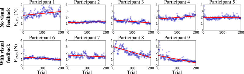
Evolution across trials of the RMS force for each participant in Exp. 2.A (upper row) and 2.B (lower row). The blue dots represent the individual trials, and the red line is the fitted linear regression. Participants 1 to 5 did not receive visual feedback (Exp. 2.A) whereas Participants 6 to 9 received online visual feedback of the force they applied on the robot (Exp. 2.B).
TABLE II.
Per-participant slope and its 95 % confidence interval of the linear function fitted across all 200 trials of Exp. 2.A and B
| No visual feedback (Exp. 2.A) | Participant | 1 | 2 | 3 | 4 | 5 |
| Slope (10−3 N/trial) |
3.0 | 0.6 | −2.4 | 2.4 | 0.3 | |
| CI upper bound (10−3 N/trial) |
4.1 | 0.8 | −1.8 | 3.0 | 1.0 | |
| CI lower bound (10−3 N/trial) |
1.9 | 0.3 | −2.9 | 1.8 | −0.3 |
| With visual feedback (Exp. 2.B) | Participant | 6 | 7 | 8 | 9 |
| Slope (10−3 N/trial) |
−2.1 | −1.4 | −8.6 | −5.8 | |
| CI upper bound (10−3 N/trial) |
−1.7 | −0.8 | −4.5 | −4.9 | |
| CI lower bound (10−3 N/trial) |
−2.4 | −2.1 | −10.0 | −6.7 |
2) Performance of the Non-Biological Profile after Practice
In Exp. 2.B (with visual feedback), pairwise t-test comparisons between the RMS force of the standard condition before practice and the constant condition after practice did not render any significant difference (p = 0.54). This suggests that although participants improved their performance in the non-biological profile with practice when guided with visual feedback, they did not surpass their performance with the biological profile, even without practice or feedback.
IV. DISCUSSION
The results of this study suggest that humans are better at moving along with a robot that follows a biological velocity pattern, compared to a non-biological one. The experiments also show that humans are able to learn a non-biological velocity pattern, but only with extensive practice and additional visual feedback. In addition, the observed improvement is limited as the performance never surpasses that obtained with a biological velocity pattern. This preference for biological movement patterns in human-robot interaction had only been demonstrated previously in visual interaction [14], [15], [16], [17], [18]. Physical interaction was only investigated by Corteville et al. but with a less quantitative approach and without examining changes with practice [21]. Our results nevertheless raise some questions that are discussed hereafter.
Effects of Arm Inertia
It may be argued that similar differences in applied forces between the different velocity patterns may have been obtained if participants had been completely passive and only dragged by the robot. The RMS force would be smallest with the biological profile because it resulted in smoother movements and, hence, smaller inertial force. To avoid this confound from passive movements, participants were explicitly told to actively move along with the robot. To verify whether participants followed this instruction, 3 participants were asked after the end of Exp. 1 to perform 5 trials of each condition in a totally passive manner. For each condition, we performed pairwise correlations between the continuous force profiles of active and passive trials. As expected, the correlations between 2 active trials or 2 passive trials were very good (0.83 ± 0.09 for active trials and 0.82 ±0.14 for passive trials). In contrast, the correlations between active and passive trials were low (0.15 ± 0.35). This finding shows that at least these 3 participants adopted different strategies when they were instructed to actively move along vs. to be passive and compliant. This suggests that in our experimental trials, participants were not completely passive and the observed results were produced by active movements.
Practice, Learning and Retention
The difference in the evolution of the applied force with practice in Exp. 2.A vs. 2.B suggests that the haptic and proprioceptive sensation of the applied force was not sufficient, or not sufficiently salient given the low level of force, to induce learning. Participants needed visual feedback to assess and guide their performance. This is consistent with earlier findings on motor learning which showed that when intrinsic feedback or knowledge of results did not suffice to assess performance, failure to provide augmented feedback led to degraded motor learning [24].
The improvement with practice observed in Exp. 2.B is consistent with the general ability of humans to adapt to a wide range of scenarios [25]. In human-robot interaction specifically, Dragan and Srinivasa observed a similar adaptation with visual interaction (i.e. observation of the robot movement) [18]. In their study, participants significantly improved their ability to interpret unnatural movement patterns in a robot after familiarization. Hence, the superior performance with biological velocity patterns in Exp. 1 does not imply that less biological patterns present a hard limit to human performance.
However, improvement in Exp. 2.B required extensive practice and performance also did not reach a plateau in the 1.5 hour-long practice. In addition, the same level of performance was reached without any practice with a biological velocity pattern. Given the long duration of Exp. 2, physiological and/or psychological fatigue might have limited the improvement. Fatigue could also explain the increase in RMS force observed in Participant 1, 2 and 4 of Exp. 2.A. Yet, as improvement required long practice, fatigue, both mental and physical, was an inevitable confound. An additional critical issue is retention, i.e. does improvement persist and transfer to other scenarios after practice? In order to be used and useful, robots interacting with humans should be controlled in a way that makes the interaction intuitive and immediately successful, without requiring any practice. Therefore, biological movement patterns should be given preference.
Predictability and Effort
The forces at play in the experiment presented are small and one may argue that the differences in force between the non-biological and biological conditions are not physically meaningful. However, there are important arenas of robotic applications where sensitivity to small forces is of high importance, such as in surgical applications. Furthermore, the current measure only includes the net external force applied by participants on the robot. Yet, it is likely that non-biological movements also cause an increase in antagonist muscle co-contraction, as the human prepares him/herself for expected perturbations. Hence, future work should also measure muscle activation to evaluate joint stiffness or impedance under different velocity patterns. Finally, even if not physically tiring, the incompatible and possibly unpredictable changes in velocities lead to discomfort and cognitive fatigue. A recent study showed that in complex object control, predictability of the object dynamics was a major determinant for human movement generation that outweighed the minimization of force [26]. Hence, complex interactions may introduce additional costs that are absent in unconstrained movements.
Generalization to Other Movements
The present evaluation of biological movement features in their effect on humanrobot physical interaction has only considered one specific example: the 2/3 power law in elliptical shapes. Future work will be directed towards showing our results also in more complex movements patterns, such as Lissajous figures or cloverleaf patterns, both in 2D and in 3D [27], [28]. Further, other robust features have described different aspects of movements, such as minimum jerk or speed-accuracy trade-off [8], [3]. Similar tests should be performed to assess whether violation of these principles in human-robot interaction also present obstacles to successful co-manipulation.
V. CONCLUSION
This study aimed to assess whether humans can adapt to non-biological patterns in robot movements when physically interacting with a robot. Specifically, we focused on the ability of humans to move along with a robot that followed either the 2/3 power law (biological pattern) or non-biological velocity profiles during an elliptic movement. Experiment 1 showed that humans performed with significantly smaller force against the robot when the robot’s trajectory followed the 2/3 power law. Despite individual variations in baseline performance, all participants exhibited the same trends across the different velocity patterns. Importantly, this was observed for both orientations of the ellipse and both types of robot handles. Experiment 2 showed that with extensive practice humans were able to lower the force applied when the robot moved with a non-biological (constant) velocity pattern, but only when visual feedback of the applied force was provided. Importantly though, even after extensive practice, the performance in the non-biological pattern did not surpass the performance obtained without any practice with the biological pattern. The results of these two sets of experiments suggest that principles of unconstrained human movement can give important insight for physically guided movements.
It needs to be kept in mind that this study examined humanrobot collaboration in a limit case, where the robot was in full control of the movement. This differs from most robotics applications where the human at least partially controls the movement. Evidently, collaboration aims to capitalize on the human’s perceptive and cognitive abilities to enhance the combined action. Nevertheless, even when the human can influence the robot motion, robotic assistance often relies on a pre-defined model of the movement [2], [21]. As movements that are optimal for humans might not be optimal for robots (due to differences in actuators and sensors), understanding the limitations of human adaptive abilities is important to facilitate human-robot physical interaction.
Acknowledgments
This paper was recommended for publication by Editor Yasuyoshi Yokokohji upon evaluation of the Associate Editor and Reviewers’ comments. This work was supported in part by NIH-R01-HD087089, NSF-NRI 1637854 and 1637824, NSF-EAGER 1548514 and 1548501 and by the Eric P. and Evelyn E. Newman Fund. Pauline Maurice is supported in part by the European Union’s Horizon 2020 Research and Innovation Program under Grant Agreement No. 731540
Footnotes
The figure only displays the frontal axis ellipse orientation, but a similar consistency is observed for the sagittal axis orientation, although with different force profiles.
References
- 1.Colgate JE, Peshkin M, Klostermeyer SH. Intelligent assist devices in industrial applications: a review. Intelligent Robots and Systems, 2003 Proceedings IEEE/RSJ International Conference on. 3:2516–2521. [Google Scholar]
- 2.Lynch KM, Liu C, Sørensen A, Kim S, Peshkin M, Colgate JE, Tickel T, Hannon D, Shiels K. Motion guides for assisted manipulation. The International Journal of Robotics Research. 2002;21(1):27–43. [Google Scholar]
- 3.Fitts PM. The information capacity of the human motor system in controlling the amplitude of movement. Journal of experimental psychology. 1954;47(6):381. [PubMed] [Google Scholar]
- 4.Lacquaniti F, Terzuolo C, Viviani P. The law relating the kinematic and figural aspects of drawing movements. Acta psychologica. 1983;54(1):115–130. doi: 10.1016/0001-6918(83)90027-6. [DOI] [PubMed] [Google Scholar]
- 5.Viviani P, Schneider R. A developmental study of the relationship between geometry and kinematics in drawing movements. Journal of Experimental Psychology: Human Perception and Performance. 1991;17(1):198–218. doi: 10.1037//0096-1523.17.1.198. [DOI] [PubMed] [Google Scholar]
- 6.Schaal S, Sternad D. Origins and violations of the 2/3 power law in rhythmic three-dimensional arm movements. Experimental Brain Research. 2001;136(1):60–72. doi: 10.1007/s002210000505. [DOI] [PubMed] [Google Scholar]
- 7.Engelbrecht SE. Minimum principles in motor control. Journal of Mathematical Psychology. 2001;45(3):497–542. doi: 10.1006/jmps.2000.1295. [DOI] [PubMed] [Google Scholar]
- 8.Flash T, Hogan N. The coordination of arm movements: an experimentally confirmed mathematical model. Journal of neuroscience. 1985;5(7):1688–1703. doi: 10.1523/JNEUROSCI.05-07-01688.1985. [DOI] [PMC free article] [PubMed] [Google Scholar]
- 9.Harris CM, Wolpert DM. Signal-dependent noise determines motor planning. Nature. 1998;394(6695):780–784. doi: 10.1038/29528. [DOI] [PubMed] [Google Scholar]
- 10.Uno Y, Kawato M, Suzuki R. Formation and control of optimal trajectory in human multijoint arm movement. Biological cybernetics. 1989;61(2):89–101. doi: 10.1007/BF00204593. [DOI] [PubMed] [Google Scholar]
- 11.Viviani P, Stucchi N. Biological movements look uniform: evidence of motor-perceptual interactions. Journal of experimental psychology: Human perception and performance. 1992;18(3):603. doi: 10.1037//0096-1523.18.3.603. [DOI] [PubMed] [Google Scholar]
- 12.Noohi E, Parastegari S, Žefran M. Computational model for dyadic and bimanual reaching movements. World Haptics Conference, 2015 IEEE. :260–265. [Google Scholar]
- 13.Reed KB, Peshkin MA. Physical collaboration of human-human and human-robot teams. IEEE Transactions on Haptics. 2008;1(2):108–120. doi: 10.1109/TOH.2008.13. [DOI] [PubMed] [Google Scholar]
- 14.Huber M, Rickert M, Knoll A, Brandt T, Glasauer S. Humanrobot interaction in handing-over tasks. Robot and Human Interactive Communication, 2008 The 17th IEEE International Symposium on. :107–112. [Google Scholar]
- 15.De Momi E, Kranendonk L, Valenti M, Enayati N, Ferrigno G. A neural network-based approach for trajectory planning in robot–human handover tasks. Frontiers in Robotics and AI. 2016;3:34. [Google Scholar]
- 16.Bisio A, Sciutti A, Nori F, Metta G, Fadiga L, Sandini G, Pozzo T. Motor contagion during human-human and human-robot interaction. PloS one. 2014;9(8) doi: 10.1371/journal.pone.0106172. [DOI] [PMC free article] [PubMed] [Google Scholar]
- 17.Kupferberg A, Glasauer S, Huber M, Rickert M, Knoll A, Brandt T. Biological movement increases acceptance of humanoid robots as human partners in motor interaction. AI & society. 2011;26(4):339–345. [Google Scholar]
- 18.Dragan A, Srinivasa S. Familiarization to robot motion. Proceedings of the 2014 ACM/IEEE international conference on Human-robot interaction. 2014:366–373. [Google Scholar]
- 19.Dumora J, Geffard F, Bidard C, Aspragathos NA, Fraisse P. Robot assistance selection for large object manipulation with a human. Systems, Man, and Cybernetics, 2013 IEEE International Conference on. :1828–1833. [Google Scholar]
- 20.Noohi E, Žefran M, Patton JL. A model for human–human collaborative object manipulation and its application to human–robot interaction. IEEE Transactions on Robotics. 2016;32(4):880–896. [Google Scholar]
- 21.Corteville B, Aertbeliën E, Bruyninckx H, De Schutter J, Van Brussel H. Human-inspired robot assistant for fast point-to-point movements. Robotics and Automation, 2007 IEEE International Conference on. :3639–3644. [Google Scholar]
- 22.Evrard P, Kheddar A. EuroHaptics conference. IEEE; 2009. Homotopy switching model for dyad haptic interaction in physical collaborative tasks; pp. 45–50. [Google Scholar]
- 23.Van der Linde R, Lammertse P. Hapticmaster-a generic force controlled robot for human interaction. Industrial Robot: An International Journal. 2003;30(6):515–524. [Google Scholar]
- 24.Salmoni AW, Schmidt RA, Walter CB. Knowledge of results and motor learning: a review and critical reappraisal. Psychological bulletin. 1984;95(3):355. [PubMed] [Google Scholar]
- 25.Shadmehr R, Mussa-Ivaldi FA. Adaptive representation of dynamics during learning of a motor task. Journal of Neuroscience. 1994;14(5):3208–3224. doi: 10.1523/JNEUROSCI.14-05-03208.1994. [DOI] [PMC free article] [PubMed] [Google Scholar]
- 26.Nasseroleslami B, Hasson CJ, Sternad D. Rhythmic manipulation of objects with complex dynamics: predictability over chaos. PLoS Comput Biol. 2014;10(10) doi: 10.1371/journal.pcbi.1003900. [DOI] [PMC free article] [PubMed] [Google Scholar]
- 27.Maoz U, Berthoz A, Flash T. Complex unconstrained three-dimensional hand movement and constant equi-affine speed. Journal of neurophysiology. 2009;101(2):1002–1015. doi: 10.1152/jn.90702.2008. [DOI] [PubMed] [Google Scholar]
- 28.Flash T, Handzel AA. Affine differential geometry analysis of human arm movements. Biological cybernetics. 2007;96(6):577–601. doi: 10.1007/s00422-007-0145-5. [DOI] [PMC free article] [PubMed] [Google Scholar]