Abstract
Poly(para-phenylene) (PPP) is a novel aromatic polymer with higher strength and stiffness than polyetheretherketone (PEEK), the gold standard material for polymeric load-bearing orthopaedic implants. The amorphous structure of PPP makes it relatively straightforward to manufacture different architectures, while maintaining mechanical properties. PPP is promising as a potential orthopaedic material; however, the biocompatibility and osseointegration have not been well investigated. The objective of this study was to evaluate biological and mechanical behavior of PPP, with or without porosity, in comparison to PEEK. We examined four specific constructs: 1) solid PPP, 2) solid PEEK, 3) porous PPP and 4) porous PEEK. Pre-osteoblasts (MC3T3) exhibited similar cell proliferation among the materials. Osteogenic potential was significantly increased in the porous PPP scaffold as assessed by ALP activity and calcium mineralization. In vivo osseointegration was assessed by implanting the cylindrical materials into a defect in the metaphysis region of rat tibiae. Significantly more mineral ingrowth was observed in both porous scaffolds compared to the solid scaffolds, and porous PPP had a further increase compared to porous PEEK. Additionally, porous PPP implants showed bone formation throughout the porous structure when observed via histology. A computational simulation of mechanical push-out strength showed approximately 50% higher interfacial strength in the porous PPP implants compared to the porous PEEK implants and similar stress dissipation. These data demonstrate the potential utility of PPP for orthopaedic applications and show improved osseointegration when compared to the currently available polymeric material.
Keywords: orthopaedic biomaterial, osseointegration, porous structure, poly(para-phenylene), polyetheretherketone
Graphical abstract
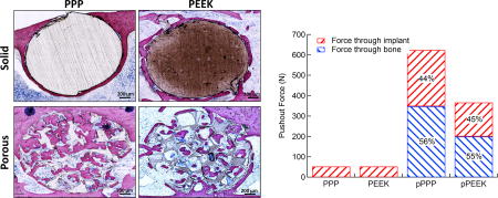
1. Introduction
Over 500,000 lumbar interbody fusion (LIF) surgeries are conducted annually in the United States, making it one of the most common surgical procedures performed [1]. Current approaches to LIFs use devices made from traditionally solid materials to restore disc height and provide stability for fusion; however, these designs do not evenly distribute loads across the vertebral endplates and can lead to micro-fractures and subsidence, which compromise the effectiveness of the procedure and contribute to adjacent level disease [2–4]. Metallic materials have been used for their high strength and bioinert properties; however, signal artifact interference during imaging makes these materials less than optimal for tracking the success of procedures. Furthermore, the high modulus of the material can lead to a material property mismatch at the interface with the bone, resulting in uneven load distribution and potential bone resorption or subsidence [5]. Alternatively, polymeric materials can avoid radiographic noise signals and have material properties closer to bone. Ideally, a load-bearing orthopaedic material would possess similar mechanical properties, such as elastic modulus and strength, to the adjacent native bone to help avoid stress concentrations and stress-shielding [6].
Porous implants have been introduced to match the mechanical properties of bone better, enhance osseointegration, and promote vascularization throughout orthopaedic devices. Osseointegration itself is a complex and highly structured biological process. First, progenitor cells must be able to migrate and propagate into the porous materials and then subsequently differentiate and through endochondral or intramembranous processes form mineralized bone [7, 8]. The newly formed bone is subsequently remodeled forming mechanically stable mature bone [9, 10]. During the early stages of this process, the interface between the bone and the device is occupied by a provisional environment (e.g., collagen fibrils and high microvasculature) that must be stabilized to allow the new bone to form [11]. Mismatched mechanical properties can induce excessive motion that can stimulate fibrosis at the interface and result in failure of the implant. Even though bulk porosity can promote interaction between the native bone and the material, it is challenging to maintain the structural integrity of the construct over the time course associated with healing. In addition, porous materials show increased wear rates or pore collapse at contact surfaces due to decreased contact area; this can lead to particle generation due to increased contact pressure [12]. Therefore, implants often have to satisfy two relatively opposing design criteria: increased porosity to improve osseointegration, while at the same time, sufficient mechanical strength to support physiologic loading. High strength polymeric materials may be suitable for porous applications while maintaining sufficient mechanical strength.
Poly(para-phenylene) (PPP) is an aromatic polymer which has higher strength and stiffness (σy=175 MPa, E=5.0 GPa) than polyetheretherketone (PEEK) (σy=118 MPa, E=2.2~4.2 GPa), the gold standard material for polymeric orthopaedic implants [13, 14]. PPP has exceptional mechanical strength and stiffness due to its repeating aromatic rings that provide strong anti-rotational biaryl bonds. Frick et al., investigated the degradation of PPP soaked in saline over a year and observed about 1wt.% increase, and mechanical properties did not show a statistical difference. To demonstrate nontoxicity, PPP soaked media was treated to mouse fibroblasts and no cell lysis or change of proliferation was observed [14]. Furthermore, PPP has an amorphous structure making it relatively insensitive to molding fabrication technique and processes. By comparison, PEEK is more challenging to manufacture (particularly with thermal processing), partially because its mechanical properties are greatly influenced by processing conditions and degree of crystallinity [15]. This ability to manufacture different architectures and use different processes while maintaining mechanical properties makes PPP a very promising potential orthopaedic biomaterial.
To date, only a limited number of studies have investigated PPP as an orthopaedic biomaterial [16–18]. We have previously investigated the mechanical behavior of PPP scaffolds with varying pore size and porosity. We determined that 70 vol% porosity with pore size of 420–500 µm closely resembled the modulus of natural trabecular bone [19]. Further, with the ability to vary porosity across a wide range, the mechanical properties of porous PPP can be tailored to match a wide variety of bone properties which can vary significantly due to age or pathology. Other studies have utilized finite element modeling of the L4–L5 motion segment in the spine and also suggested a 70 vol% porous PPP interbody spacer could be sufficiently compliant, reduce stress concentrations, and still withstand axial compressive loading in the spine [20]. While the mechanical properties of porous PPP scaffolds have been studied, the potential osteocompatibility and osseointegration of these scaffolds have not been demonstrated in a biological setting.
The purpose of this study was to investigate the performance of PPP scaffolds in vitro and in vivo, as well as to evaluate the biomechanical properties associated with bone integrating with the polymeric scaffolds using finite element analysis (FEA). In addition, we manufactured both solid and porous scaffolds from PPP and PPP and compared osseointegration. Four different scaffold groups were used in this study: 1) solid PPP, 2) solid PEEK, 3) porous PPP and 4) porous PEEK. Osteocompatibility was assessed by culturing pre-osteoblasts on disc-shaped wafers of each material and evaluating osteogenic differentiation. Osseointegration was assessed by implantation of cylindrical material scaffolds into circular defects in the rat tibia metaphysis. We hypothesized that the 70 vol% porosity of PPP material would provide enhanced osseointegration through the entire construct. The mechanical response of porous implants with bone ingrowth was analyzed using a finite element push-out test. Implants with simulated bone ingrowth were subjected to a known displacement to measure reaction forces and stress dissipation within the implant to determine push-out force. Studying these structured materials may provide insight into the potential utility of PPP as an orthopaedic biomaterial.
2. Materials and methods
2.1 Material Fabrication
Porous and solid implants were manufactured via compression molding using a uniaxial testing machine (Insight 30, MTS Systems, Eden Prairie, MN, USA). PPP and PEEK powder (Solvay PrimoSpire PR-250 and KetaSpire KT-820) were provided by Solvay Specialty Polymers (Alpharetta, GA, USA) and were mixed to a volume ratio of 30:70 polymer powder-to-salt for porous scaffolds using salt crystals sifted to between 420–500 µm as used in previous studies by the authors [21]. Solid implants were molded using pure polymer powder. PPP scaffolds were heated to 180°C for 20 minutes in a 2 mm × 18 mm mold and then compressed to a stress of 85 MPa for 20 minutes. PEEK scaffolds were heated to 370°C and compressed for the same time and stress. After compression, molds were removed from the oven and immediately quenched to ambient conditions in water (~22°C). Porous scaffolds were placed in rapidly stirred water baths for 24 hours at 60°C to ensure all salt was dissolved away. Scaffolds were then placed in a vacuum oven for 1 hour at 80°C to dry. All four surfaces were measured for average surface roughness, Sa, with a laser confocal microscope (LEXT OLS4000, Olympus, Center Valley, PA, USA) using a 20× objective, 100 nm step size, λc = 100 µm and 150 µm × 150 µm evaluation area (n=3, 3 spots per sample).). Morphometric analysis of the scaffold pores was conducted using the BoneJ plugin for ImageJ software (National Institutes of Health, USA). Specifically, strut thickness (µm), strut connectivity (connections/cm3), structural model index, and anisotropy of the structure were quantified. Following material fabrication, the modulus of each porous scaffold type was measured using dynamic mechanical analysis and simulated using FEA. Each scaffold was potted in a custom fixture and cyclically strained 0.2% at 1 Hz to measure the elastic modulus. FE models were compressed by 2% of their overall length, and reaction forces were recorded to measure the apparent modulus of the material.
2.2 In vitro cell proliferation and differentiation
To assess cellular compatibility, solid and porous samples of both materials were prepared as disc-shaped wafers (15.4 mm in diameter, 0.6 mm in thickness) and press fit into a 24-well plate. Mouse pre-osteoblasts (MC3T3-E1; ATCC, Manassas, VA, USA) were cultured on the wafer and maintained in alpha Minimum Essential Medium (α–MEM, Life Technologies, Carlsbad, CA, USA) supplemented with 10% fetal bovine serum (FBS; Atlanta Biologicals, Lawrenceville, GA, USA), 1% antibiotics-antimycotics solution (Thermo Scientific, Rockford, IL, USA) at 37°C in a 5% CO2 incubator. Cells were seeded on the materials or on tissue culture plate (TCP) as positive control. Seeding density was optimized by surface dimension (5,000 cells/cm2) and cells were cultured for 1, 3 or 5 days (n=2~4). At each incubation time point, cell proliferation was measured by Alamar blue assay (Invitrogen, Grand Island, NY, USA) for mitochondrial metabolic activity. Each group was treated in Alamar blue solution for 4 hours, and then fluorescence was measured with a micro-plate reader by excitation at 530 nm and emission at 590 nm.
To induce osteogenic differentiation, cells were seeded at 5,000 cells/cm2 and cultured for one day to allow cell attachment. The culture medium was then replaced with differentiation medium composed of normal culture medium supplemented with 6 mM β-glycerophosphate, 1 nM dexamethasone, 50 ng/ml thyroxine, 50 µg/mL ascorbic acid 2-phosphate. All chemicals were purchased from Sigma Aldrich (St. Louis, MO, USA). Differentiation medium was changed every 2–3 days. Alkaline phosphatase (ALP) activity is an early marker of osteoblast differentiation and was measured at 7 days after initiation of differentiation media. Cells were washed twice with phosphate-buffered saline (PBS) and lysed in lysis buffer (10 mM Tris–HCl pH 8.0, 1 mM MgCl2, and 0.5 % Triton X-100). Cell lysate was centrifuged for 5 min at 4°C, 13,000 g. The supernatant was harvested and ALP activity was measured using an ALP assay kit (Sigma-Aldrich) according to the manufacturer’s protocol. Separate samples were used to measure calcium deposition at 21 days after differentiation (n=2~4). For the quantification of calcium in culture, plates were treated in 1N acetic acid overnight at 4°C on plate shaker. Extracted calcium was transferred to a microtiter plate in triplicate and total amount of calcium was measured by colorimetric Arsenazo III reagent treatment (Diagnostic Chemicals Ltd, Oxford, CT, USA).
2.3 In vivo animal surgery
All animal care and experimental procedures were approved by the Veterans Affairs Institutional Animal Care and Use Committee (IACUC) and carried out according to the guidelines. Thirteen-week-old male Sprague-Dawley rats (n=6/groups, Charles River Labs, Wilmington, MA, USA) were used in this study. After pre-operative preparation, animals were anesthetized by isoflurane inhalation (2~3%). The proximal tibia was exposed by a 1.5–2 cm longitudinal incision through the skin. The muscle tissue was then separated using blunt dissection along the muscle bundle divisions. One transcortical hole (2.5 mm diameter) was created at the proximal tibial metaphysis using a low-speed rotational drill speed (~800 rpm) under cooling with sterile saline. One sterile cylindrical scaffold of each sample group was placed into the predrilled holes through both cortices. The muscle was then sutured closed with absorbable 4-0 sutures and skin and closed with wound clips. Buprenorphine SR (0.03 mg/kg; 1 ml/kg) was used as an analgesic and applied via subcutaneous injection.
2.4 Digital radiographic evaluation
Animals received serial X-ray imaging at 2, 4, 6 and 8-weeks post-surgery. In vivo X-ray scanning (In-Vivo Xtreme, Bruker Corp., Billerica, MA, USA) was performed on the tibial region at an exposure time of 15 s and a voltage of 25 kV. To assess bone ingrowth throughout implant and osseointegration, micro-computed tomography (micro-CT) scans (Micro-CT40, Scanco Medical, Bruttisellen, Switzerland) were performed following euthanasia at 8 weeks (n=6/groups). Samples were scanned with a 20 µm voxel size at a voltage of 55 kVp and a current of 145 µA. The bone volume of interest was assigned by contouring the perimeter of each implant. Three dimensional reconstructions were obtained from evaluations of 500 slices of two-dimensional X-ray images. New bone formation was evaluated by application of a global threshold corresponding to 50% of the cortical bone density (386 mg hydroxyapatite/cm3) [22].
2.5 Histological analysis
After euthanasia at 8 weeks post-surgery, tibial explants were fixed with 10% neutral buffered formalin (10% NBF) for 3 days then stored in 70% ethanol until processing. Samples were dehydrated through ascending grades of alcohol and cleared in xylene. To observe mineralized bone structure, fixed bone samples were processed in plastic (methyl methacrylate; MMA) resin for a week. After embedding, plastic blocks were cut using a grinding system (EXAKT 400 CS, Exakt Technologies, Inc., Oklahoma City, OK, USA) to an average thickness of 25 µm. Sections were stained with methylene blue and acetic fuchsin or Goldner’s Trichrome staining (n=1/each staining). Images were obtained with the Axio Observer Z1 microscope (Carl Zeiss, Jena, Germany) and captured using the Axio Vision software (Carl Zeiss Micro Imaging, Thornwood, NY, USA).
2.6 Finite-Element (FE) simulated push-out test
Micro-CT scans of the implants were segmented using Simpleware ScanIP (Synopsys, Mountain View, CA, USA). Percent porosity was verified following segmentation by subtracting material volume from the total volume of the cylinder. A 2.6 mm length of each implant was computationally modeled and embedded in a bone block to simulate a push-out test. Bone ingrowth was modeled as a layer of bone following the shape of the pores through the implant. Simulated ingrowth was modeled to match ingrowth percentages measured from the rat model scans. Material properties were assigned as shown in Table 1. The coefficient of friction between bone and implants was defined as 0.25 for all implant types [23, 24]. To increase computational efficiency, it was assumed that the implant would show symmetry about its axes and a half implant was modeled in the case of the porous scaffolds. Symmetric boundary conditions were applied on the plane of symmetry for the implant, and reaction forces were doubled after measurement to determine the push-out for the full implant. Perfectly plastic behavior was assumed for all materials after yielding. The modulus of newly formed bone was estimated as 13 GPa based on mineral density measurements using the empirical relationship developed by Wagner et al [25]. The simulated push-out was performed using ABAQUS (3DS SIMULIA, Johnston, RI, USA). The bone block was pinned in all directions, and a displacement equivalent to 2% of the implant length was applied to the implant and ingrown bone at the top of the block. This loading level was chosen to exceed that of the ultimate strain of cortical bone. Reaction forces at the surface of the implant and bone were taken to measure load sharing and total push-out force. Average stress at 0, 20, 40, 60, 80, and 100% of the length of the implant was calculated to determine stress dissipation within the scaffold. A model of this method can be seen in the supplementary figure (Figure. S1).
Table 1.
Material properties assigned to bone and scaffolds in simulated push-out test
| Yield Stress (MPa) | Elastic Modulus (MPa) | Poisson’s Ratio | |
|---|---|---|---|
| Bone | 178 | 13,000 | 0.3 |
| PEEK | 118 | 4,100 | 0.3 |
| PPP | 175 | 5,000 | 0.3 |
2.7 Statistical analysis
Statistical significance for quantitative results was assessed with one-way analysis of variance (ANOVA) with Tukey’s multiple comparison post-hoc test. As appropriate (and specified in the results section), unpaired Student's two-tailed t-tests were used for analysis. P-values less than 0.05 indicated statistical significance. Numeric values are presented as the mean ± S.E.M. All statistical analysis was performed using GraphPad Prism 5.0 software (GraphPad, La Jolla, CA, USA).
3. Results
3.1 Scaffold Fabrication
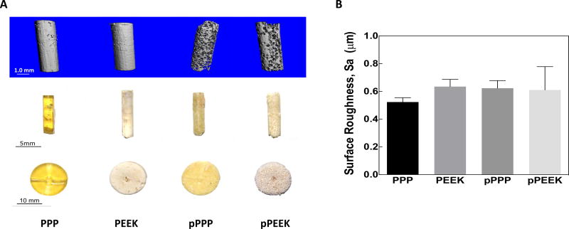
Four types of materials were fabricated for this study, including solid and 70 vol% porous scaffolds made from either PPP or PEEK. Representative images of these scaffolds are presented in Figure 1A. The solid PPP samples are visually transparent and have a yellowish color, compared to solid PEEK samples that were opaque and brown Both sets of PPP samples were more uniform in color and appearance, although the porous PPP sample lost its transparency due to the presence of pores. PEEK samples had a variation in color, which is due to the difficulty of producing the samples as well as changes in the degree of crystallinity throughout the samples. The porosity of representative scaffolds was measured using 3D segmented micro-CT scans to be 68–71%(st. dev.= .021, n=3). In addition, micro-CT verified that all salt particles had been successfully leached out of the scaffold during manufacturing. Surface roughness (Sa) was measured for each sample and were not statistically different between groups (Figure 1B. one-way ANOVA, Tukey, n=3; PPP: 0.5237 +/− 0.0304 µm, PEEK: 0.6349 +/− 0.0522 µm, pPPP: 0.6233 +/− 0.0544 µm, pPEEK: 0.6111 +/− 0.1679 µm). Data and microscopy regarding pore sizes using this method can be found in the previous studies by the authors [21]. Pore morphometry for porous PPP and PEEK scaffolds showed strut thickness values of 112.4 µm and 100 µm for PPP and PEEK, respectively. Additionally, strut connectivity densities for PPP and PEEK were measured to be 54780 and 78228 connections/cm3, respectively. The structural model index calculation for the scaffold indicated the pores were primarily oblong with rounded edges with SMI values of 3.08 and 2.515 for PPP and PEEK, respectively, where 0 indicates a flat structure, 3 indicates a cylindrical shape, and 4 indicates a spherical pore. The scaffold structure was found to be primarily isotropic with PPP and PEEK scaffolds showing degrees of anisotropy of 0.13 and 0.20. Representative images of the trabecular thickness can be seen in Figure S3 in the supplement.
Figure 1. Photographs and surface roughness of the materials.
(A) Both solid and 70% porous PEEK and PPP samples were manufactured. (Left to right: solid PPP, solid PEEK, porous PPP, porous PEEK). Thin-disk samples (Bottom) were used for in vitro studies, while cylindrical samples were implanted into rat tibiae (Middle). Micro-CT images (Top) are provided for the cylindrical samples to better show material porosity. (B) All four surfaces were measured for average surface roughness, Sa.
The apparent modulus of the porous scaffolds was measured using DMA and was found to be 212 ± 2.8 MPa (n=2) for porous PEEK and 231 ± 19.8 MPa (n=2) for porous PPP. These results closely matched those of the simulated compression test of the materials which showed moduli of 153 and 213 MPa for PEEK and PPP respectively. Data from this comparison allowed for validation of the finite-element model used in the study as the direct measurement of the scaffold apparent modulus correlated well with the finite-element compression test of the scaffolds.
3.2 In vitro cellular compatibility and mineralization
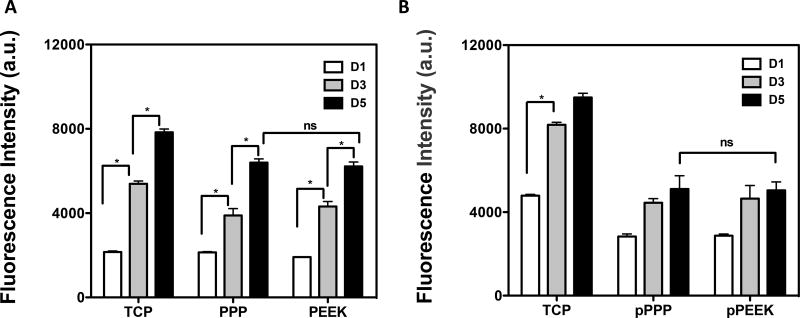
Mouse pre-osteoblasts (MC3T3-E1) were seeded onto disc-shaped wafers (15.4 mm in diameter, 0.6 mm in thickness) and cell proliferation was measured to assess if the materials could support cell adherence and growth. The porous material scaffolds had five times more surface area compared to the solid scaffolds, so the seeding cell density was normalized by the scaffold dimensions (5,000 cells/cm2). MC3T3 cells adhered onto the solid materials and no difference was observed from TCP control (Figure 2A). Adherent cells proliferated over time, and there was no significant difference in cell number between the different material groups on the solid materials at day 5 (Student's t-test, p=0.5425, PPP vs PEEK at day 5), suggesting that these materials could support cell adhesion and proliferation. The porous scaffolds showed a smaller number of cells adhered on the first day compared to TCP (one-way ANOVA, Tukey, p<0.0001 vs. cells on TCP). An increase in proliferation was observed with time (day 1 and 3), then cells reached peak proliferation after day 3 in culture. No difference was seen in cell number between porous PPP and PEEK (Figure 2B).
Figure 2. Cells were able to adhere and grow on/in the materials.
Mouse pre-osteoblasts (MC3T3-E1) were seeded on (A) solid scaffolds (PPP, PEEK), (B) porous scaffolds (pPPP, pPEEK). The metabolic activity was measured at days 1, 3 and 5 to assess cell proliferation. MC3T3 cells showed significantly increased proliferation after seeding. There were no differences in growth in between PPP and PEEK. *p<0.05; n=2–4; data presented as mean ± S.E.M.
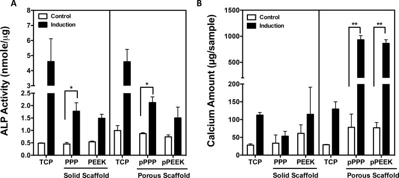
To evaluate osteogenic differentiation, ALP activity and calcium deposition were measured at Day 7 and Day 21, respectively, after treatment with osteogenic induction media. Cells grown on solid and porous PPP scaffolds showed a significant increase in ALP activity after differentiation (one-way ANOVA, Tukey, p<0.05) (Figure 3A). Bulk porosity increased the total amount of calcium deposition from porous PPP and porous PEEK scaffolds by 11.9-fold and 11.2-fold after differentiation, respectively (one-way ANOVA, Tukey, p<0.001) (Figure 3B). Altogether, the porosity of the materials showed a significant improvement in osteocompatibility for both materials compared to the solid materials and a possible advantage for osseointegration in vivo.
Figure 3. Porous surfaces showed significantly increased osteogenic potential.
Mouse pre-osteoblasts (MC3T3-E1) were treated osteogenic induction media. To confirm osteogenic differentiation, (A) ALP activity and (B) calcium amount were measured at d7 and d21 respectively after differentiation. Cells grown on porous PPP scaffold showed a significantly increase in ALP activity and calcium deposition. *p<0.05, **p<0.001; n=2~4; data presented as mean ± S.E.M.
3.3 Implant osseointegration
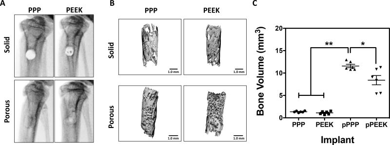
To investigate material osseointegration, we implanted solid and porous cylindrical materials into defects in the rat tibia. X-ray radiographs were taken at 8-weeks post-surgery to visualize bone formation (Figure 4A). For solid implants, an empty cylindrical region in the tibial metaphysis that matched the surgically created defect was still identifiable by radiograph at the 8-week time point. Conversely, radiographs of rats with porous implants showed filling of the defect, suggestive of bone ingrowth and mineralization. To confirm the X-ray studies, tibiae were analyzed ex vivo using micro-CT, and bone formation was quantified (Figure 4B). Solid implants from both materials showed a thin layer of new bone formation along the material surface, while the porous materials showed mineralization not only on the surface but also throughout the entire implant. The bone volume (BV) was measured within the pores of the implants; overall, there were no significant differences between solid (non-porous) implants (PPP 1.36±0.07 mm3, PEEK 1.11±0.14 mm3) (Figure 4C). The porous PPP implants had a significantly higher BV compared to the other three implant types (11.57±0.38 mm3; p<0.0001 vs. solid PPP or PEEK). Specifically, porous PPP implants demonstrated a 40% increase in BV compared to porous PEEK (p=0.0176 vs. porous PEEK). These data suggest that porous PPP may be an effective material for osseointegration due to remarkable mineralization than other materials.
Figure 4. Bone growth throughout porous materials, especially PPP showed significantly increased bone ingrowth.
A) In vivo x-ray radiographs at 8-weeks post-surgery. (B) representative micro-CT reconstructions of same specimens from x-ray images. (C) Quantitative measurement of mineralized bone volume of implants. Solid scaffolds showed no significant difference of BV between groups. Porous PPP explants showed significantly increased BV value compared to any other explants. *p<0.05; **p<0.0001; n=6; data presented as mean ± S.E.M.
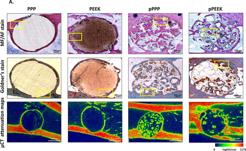
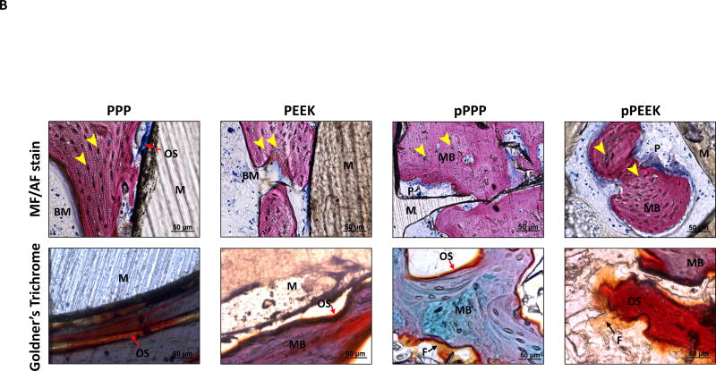
Histological assessment showed bone formation throughout the porous PPP and porous PEEK structures (Figure 5A). Bone cells (osteocytes marked with a yellow arrowhead at Figure 5B, magnified images of Figure 5A) were observed in the mineralized new bone around the solid implants (stained as pink from MF/AF staining or stained as purple to green from Goldner’s staining). In the porous implants, cubically shaped pores were filled with mineralized bone (Figure 5B). Similar to micro-CT analysis, porous PPP samples showed qualitatively more mineralized new bone formation, enhanced cell infiltration, and less fibrosis (yellow stain from Golder’s trichrome staining) within the implant compare to porous PEEK implants. Furthermore, histomorphometric analysis suggested porous implants were observed enhanced mineralized bone area, perimeter, and width than solid implants; moreover, porous PPP implants demonstrated quantitatively increased mineralization (Figure S2). Representative micro-CT attenuation heat maps also showed the differences in new bone formation between porous groups (Figure 5A).
Figure 5. Osseointegration of implant and bone ingrowth.
To demonstrate bone ingrowth, implanted bones were harvested at 8-weeks post-op and evaluated via methylene blue acetic fuchsin staining, Goldner’s trichrome staining and representative mineral attenuation maps from micro-CT (n=1) (A) coronal section of implant with adjacent tissue, (B) higher magnification of selected regions (yellow box). Histology suggested bone interaction with solid scaffold surfaces and ingrowth throughout the porous structure. Notably, pPPP showed enhanced cellularization and substantial bone formation. MB (Matured bone, stained as pink from MF/AF staining or purple to green from Goldner’s staining); M (Material, stained as brown); OS (Osteoid seam, red arrow); F (Fibrotic tissue, black arrow); Osteocyte (yellow arrowhead); BM (Bone marrow); P (Inner pore structure). Scale bars: 200 µm (original), 50 µm (higher magnification)
3.4 FE Simulated push-out test
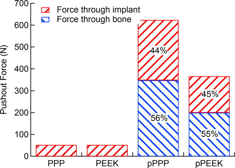
Using segmented implants from micro-CT scans, 3D models of implants with simulated bone ingrowth were generated and underwent a simulated push-out test. Reaction forces and load sharing were calculated for each type of implant. Load sharing and total push-out force are shown in Figure 6. Porous PEEK had a total push-out force of 367 N while porous PPP had a push-out force of 624 N. These forces equate to shear strengths of 21.3 and 36.5 MPa for PEEK and PPP, respectively. The load sharing between bone and implant in both porous materials were approximately the same at 45% and 55% for implant and bone, respectively. Both PEEK and PPP solid implants had push-out forces of 53 N with 100% of the force transmitting through the implant, as there was no bone ingrowth. The shear strength of both solid implants was 3.08 MPa.
Figure 6. Total push-out force and load sharing behavior of solid/porous PEEK and PPP.
Both solid and 70 vol% porous PEEK and PPP samples were subjected to a simulated FE push-out test (n=1). Reaction forces from the bone and implant were taken to determine load sharing. Porous PPP showed significantly higher push-out force than porous PEEK. Load sharing between the bone and implant in porous scaffolds was nearly identical between both materials. Both solid scaffolds showed identical push-out force with all force transmission through the implant as there was no bone ingrowth.
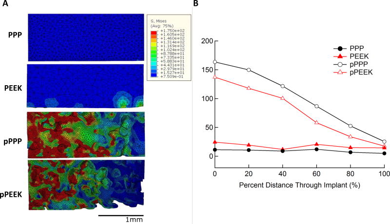
Stresses were visualized as a heat map on the FE model to show dissipation qualitatively, and average stresses were taken along the length of the implant to quantify the amount of stress dissipation within the implant. Stress dissipation within the various implants is shown in Figure 7. Both solid implants showed relatively constant stress throughout the implant length with PEEK showing slightly higher stresses at all positions compared to PPP. Both porous implants showed a nearly linear decrease in stress from the initial surface to the end with average stresses in each implant decreasing approximately 80%. The porous PPP implant, which had greater bone ingrowth, showed higher average stresses throughout the implant compared to the porous PEEK. Stress as a function of distance through the implant is shown in Figure 7B. Von Mises stresses in the implant were plotted with the loaded end on the left for all implants in Figure 7A with a color map representing various levels of stress from 0 MPa (dark blue) to 175 MPa (red). Stress dissipation in the implants can be seen as the high-stress red areas transition to green and blue along the implant length. Both porous implants showed a similar response, with the majority of stress being dissipated in the first half of the implant.
Figure 7. Stress dissipation within scaffolds during simulated push-out test.
Heatmaps of von Mises stress within each scaffold type (left) showed little stress in the center of the implant for both solid PPP and solid PEEK while both porous scaffolds showed high stress at the top surface of the implant which then dissipate moving through the scaffold. Average stresses in the implant at equally spaced intervals (right) in the implant show porous PPP and PEEK having similar stress dissipation response while there is no dissipation within the solid scaffolds.
4. Discussion
The purpose of this study was to investigate the biological response of PPP as a novel load-bearing orthopaedic material, and evaluate the mechanical properties associated with bone ingrowth by FE stimulated push-out simulation. We hypothesized that high porosity throughout PPP implants (this study used 70% porosity) would allow for enhanced osseointegration and increased push-out force compared to solid implants as well as porous PEEK implants. The hypothesis was confirmed as this study demonstrated that porous implants showed higher cellular compatibility and osteogenic potential in vitro and increased osseointegration in vivo compared to solid implants. Porous PPP also showed higher osseointegration and total bone volume following implantation when compared to both solid PPP, solid PEEK and porous PEEK. Finite element analysis predicted that this increased bone ingrowth would result in a higher push-out force compared to porous PEEK and both solid implants.
While many studies have analyzed the biological response to various porous scaffolds, previous studies have not yet examined the cell proliferation or osteogenic potential of PPP scaffolds, either with solid or porous architectures. This study demonstrated that mouse pre-osteoblasts could adhere and proliferate on both solid and porous PPP and PEEK scaffolds. While cell growth on porous materials peaked at day 3, cells grown on solid surface continuously proliferated over time. The difference in growth behavior could be interpreted as a consequence of geometric difference between in two different scaffolds (2D surface vs. 3D surface). Additionally, several reports demonstrated that small pore sizes (96–150 µm) could facilitate cell attachment and proliferation [26]; however, a larger pore size was efficient to accommodate new bone formation and vascularization [27]. Our data also demonstrated substantial bone ingrowth within 420–500 µm pore size throughout the porous networks (Figure 4). Early osseointegration has been shown to be influenced by surface topography [28, 29]. Many orthopaedic implants are engineered with microscale surface roughness (Sa: 1~2 µm) to mimic the osteoclast resorption line and promote osseointegration [30]. Osteoblasts preferentially adhere to the curved surface and can then proliferate and mineralize by producing bone cement proteins (e.g., osteopontin, bone sialoprotein, and proteoglycans) [31]. In this study, the surface roughness of PPP and PEEK were slightly less rough than the osteoclast resorption surface; however, no significant differences were found in the roughness of the two materials or the subsequent pre-osteoblast proliferation or mineralization on the two materials (Figure 2 and 4). Osseointegration is not solely determined by 2D surface roughness, and both 2D and 3D architecture may strongly influence bone ingrowth. As shown in Figure 3, osteogenic potential was increased in porous scaffolds compared to solid scaffolds. Similar reports have previously been observed, [32, 33] demonstrating bone cells in 3D culture secreted enhanced osteogenic specific proteins (e.g., osteonectin, type I collagen and alkaline phosphatase) and showed a 10-fold increase in mineral deposition compared to 2D cultures. Additionally, porous structures can support increased hematoma retention time; this stage consists of platelets and fibrin fibers that subsequently promote infiltration of inflammatory cells and stem cells into the injured site favoring angiogenesis and osteogenesis. Our data clearly demonstrated that the pores were filled with infiltrated cells and mineralization throughout the porous structures. However further analysis into the recruited cell populations remains to be investigated. It has been shown that sequential bone ingrowth into porous structures leads to mechanical interlock and yields greater fixation strength; Fujibayashi et al., implanted porous titanium metal spacers into five patients with lumbar spine disease and reported long-term stability and clinical success by 6 months [34, 35]. While it was not investigated in this study, the adsorption of proteins to the surfaces of the two materials and the cellular infiltration into the porous networks, could be a possible explanation for differences in osseointegration. Further work investigating this mechanism would provide significant insight into the increased osseointegration with the PPP scaffolds.
Osseointegration is a time-dependent healing process beginning with cell adhesion [36] to the implant surface (i.e., peri-implant tissue formation) and matrix formation [37] subsequently leading to mineralization of the tissue [11]. Successful osseointegration can be categorized by direct anchorage of an implant without fibrotic tissue formation, which can interfere with the direct contact at the bone-implant surface resulting in implant failure and associated increased morbidity [38]. The porous PPP implants, as seen in Figure 5, were filled with cells and mineralized bone, consistent with micro-CT attenuation maps. On the contrary, porous PEEK showed significantly decreased mineralized bone ingrowth measured by micro-CT analysis and also showed some fibrotic tissue formation in the pores by histology. Evans et al., reported that surface-porous PEEK implants were filled with cellularized, mineralized bone with less fibrotic tissue compared to smooth surfaces [22]. In that study, the implants had a different pore size and porosity, 279.9 ± 31.6 µm and 67.3 ± 3.1% respectively, and were only on a thin surface layer; whereas, our implants had a larger pore size and porosity throughout the whole implant, which might have affected bone ingrowth. The difference in the material topography (surface porous structure vs entire porous structure) may be a critical factor affecting the biological response as well. While we did not do an isolated evaluation of mineralization into the surface layer of these constructs, it was apparent that more mineral formed in the porous PEEK samples in the surface layer compared to the central regions and may account for these differences. Overall, both studies showed significant osseointegration into these high strength polymeric scaffolds with porous structures and suggest that the architecture and porosity is a critical factor in improving osseointegration of these materials.
The strong correlation between the measured and simulated apparent modulus measurements helped verify the utility of our finite element model. As such, we believe the simulated pushout test provided accurate results which match those seen in other studies. Based on the simulated push-out test, porous PPP showed a significantly higher push-out force compared to porous PEEK. This difference is likely attributed to the increased bone ingrowth seen during implantation in porous PPP. Additionally, PPP has a significantly higher yield stress compared to PEEK, and as such would show increased reaction forces during push-out. The total push-out forces were found to be comparable to those measured in previous studies. Oonishi et al., found surface porous titanium implants to have shear strengths of 25.4 MPa [27]. Additionally, Guyer et al., showed surface porous titanium and solid PEEK implants to have shear strengths of 10.2 and 1.5 MPa respectively [39]. Whereas we found push-out shear strengths of 21.3 and 36.5 MPa for porous PEEK and PPP respectively and 3.08 MPa for both solid implants. The differences in the finite element push-out and the experimental values seen here are likely due to the idealized nature of the model, with the bone perfectly following the pore shape with no gaps in bone growth. Both implants showed similar load-sharing properties, as the ratio of the bone modulus to that of the implants was similar in both cases. Furthermore, the porosity of each implant was the same, and as such there would be a similar cross-sectional area for bone and implant in each case.
In the case of load dissipation, both porous PEEK and PPP exhibited a similar response by dissipating approximately 80% of the stress through the implant in a linear fashion. The porous PPP implant displayed higher stresses through the entire scaffold than porous implant. This phenomenon was due to the implants being modeled as a perfectly plastic material; the higher yield stress in PPP (approximately 50% higher than PEEK) allowed for an overall higher amount of loading before yield at all points along the implant. The solid implants, on the other hand, showed little stress dissipation, transferring most of the stress from the implant top to bottom. This observation may be explained by the majority of the stress being dissipated by struts within the porous implant and bone yielding during push-out. In solid implants, no such structure was available for dissipation of stresses applied to the implant. The ability of porous structures to dissipate this stress also afforded itself to more ideal load sharing with the bone and showed a behavior which could not be captured by solid implant designs.
The solid implants used in this study are representative of current spinal fusion cage designs; made up of solid materials, which can only interface with the bone at their surface and have moduli significantly higher than the bone at the vertebral endplate (typically by an order of magnitude) [40]. This disparity between the mechanical properties of the implant and vertebral bone is believed to be a leading cause of complications post-implantation due to subsidence [41]. The high modulus of the implant relative to the bone leads to stress-shielding and stress concentrations on the vertebral endplate, increasing the likelihood of subsidence. Porous PPP represents a possible solution to these limitations as it possesses a modulus much closer to that of trabecular bone and, as we modeled in this study, can dissipate stress within the implant. In addition, the finite element models presented that porous PPP evenly shared the load with the ingrown bone and dissipated stress upon loading. These two results together suggest that porous PPP would be able to minimize stress shielding, decreasing the likelihood of subsidence following fusion with a porous PPP device. Also, the ability to interface with the bone throughout the implant could allow for increased strength due to the mechanical interlocking of the bone and the implant rather than simply due to friction at the surface [34]. However, despite the enhanced osseointegration into porous PPP, further fundamental investigation is needed such as protein adsorption to the surface and fibrin network formation to influence the local osseointegration within the scaffolds.
In conclusion, the porous PPP material demonstrated excellent cellular compatibility and strong integration with living bone, which are critical factors in load-bearing implants. The use of porous PPP in orthopaedic implants can offer many benefits, which may be advantageous compared to current spinal fusion devices, including ones made from porous PEEK. Specifically, the high yield stress and modulus of PPP allows for the introduction of high porosity in the implant without sacrificing mechanical integrity. Moreover, the ability of porous polymer implants in general to dissipate stress demonstrates a fundamentally unique behavior which cannot be captured by solid implants or metal implants. The exceptional properties of PPP suggest that it could be uniquely suited to such applications. PPP is a highly promising orthopaedic biomaterial with relative flexibility in manufacturing processes, a favorable biological response, and comparable mechanical properties to native bone.
Supplementary Material
Statement of Significance.
PEEK has been widely used in orthopaedic surgery; however, the ability to utilize PEEK for advanced fabrication methods, such as 3D printing and tailored porosity, remain challenging. We present a promising new orthopaedic biomaterial, Poly(para-phenylene) (PPP), which is a novel class of aromatic polymers with higher strength and stiffness than polyetheretherketone (PEEK). PPP has exceptional mechanical strength and stiffness due to its repeating aromatic rings that provide strong anti-rotational biaryl bonds. Furthermore, PPP has an amorphous structure making it relatively easier to manufacture (via molding or solvent-casting techniques) into different geometries with and without porosity. This ability to manufacture different architectures and use different processes while maintaining mechanical properties makes PPP a very promising potential orthopaedic biomaterial which may allow for closer matching of mechanical properties between the host bone tissue while also allowing for enhanced osseointegration. In this manuscript, we look at the potential of porous and solid PPP in comparison to PEEK. We measured the mechanical properties of PPP and PEEK scaffolds, tested these scaffolds in vitro for osteocompatibility with MC3T3 cells, and then tested the osseointegration and subsequent functional integration in vivo in a metaphyseal drill hole model in rat tibia. We found that PPP permits cell adhesion, growth, and mineralization in vitro. In vivo it was found that porous PPP significantly enhanced mineralization into the construct and increased the mechanical strength required to push out the scaffold in comparison to PEEK. This is the first study to investigate the performance of PPP as an orthopaedic biomaterial in vivo. PPP is an attractive material for orthopaedic implants due to the ease of manufacturing and superior mechanical strength.
Acknowledgments
This research was supported by NIAMS of the NIH under award number R21AR065713 as well as the State of Colorado Biological Discovery and Evaluation Grant Program. We thank Dr. Thanh Doan (Department of Orthopaedics, Emory University) for his helpful discussion and insights, Mesfin Teklemariam (Department of Orthopaedics, Emory University) for his huge support for histomorphometric analysis, and Dr. Colleen Oliver (Atlanta VA Medical Center) for her great support on animal work. The authors would also like to thank Solvay Specialty Polymers for financial and material support.
Footnotes
Publisher's Disclaimer: This is a PDF file of an unedited manuscript that has been accepted for publication. As a service to our customers we are providing this early version of the manuscript. The manuscript will undergo copyediting, typesetting, and review of the resulting proof before it is published in its final citable form. Please note that during the production process errors may be discovered which could affect the content, and all legal disclaimers that apply to the journal pertain.
Conflict of interests
CMY has equity in a biomedical device company, MedShape, Inc.. CMY and CPF have equity in a biomedical device company, Impressio, Inc.
References
- 1.M.R. Group. Spinal Implants | US | 2015 | Market Analysis. 2015 [Google Scholar]
- 2.Beutler WJ, Peppelman WC., Jr Anterior lumbar fusion with paired BAK standard and paired BAK Proximity cages: subsidence incidence, subsidence factors, and clinical outcome. Spine J. 2003;3(4):289–93. doi: 10.1016/s1529-9430(03)00061-5. [DOI] [PubMed] [Google Scholar]
- 3.Kim MC, Chung HT, Cho JL, Kim DJ, Chung NS. Subsidence of polyetheretherketone cage after minimally invasive transforaminal lumbar interbody fusion. J Spinal Disord Tech. 2013;26(2):87–92. doi: 10.1097/BSD.0b013e318237b9b1. [DOI] [PubMed] [Google Scholar]
- 4.Chrastil J, Patel AA. Complications associated with posterior and transforaminal lumbar interbody fusion. J Am Acad Orthop Surg. 2012;20(5):283–91. doi: 10.5435/JAAOS-20-05-283. [DOI] [PubMed] [Google Scholar]
- 5.Ryan G, Pandit A, Apatsidis DP. Fabrication methods of porous metals for use in orthopaedic applications. Biomaterials. 2006;27(13):2651–70. doi: 10.1016/j.biomaterials.2005.12.002. [DOI] [PubMed] [Google Scholar]
- 6.Navarro M, Michiardi A, Castano O, Planell JA. Biomaterials in orthopaedics. J R Soc Interface. 2008;5(27):1137–58. doi: 10.1098/rsif.2008.0151. [DOI] [PMC free article] [PubMed] [Google Scholar]
- 7.Davies JE. Mechanisms of endosseous integration. Int J Prosthodont. 1998;11(5):391–401. [PubMed] [Google Scholar]
- 8.Franchi M, Fini M, Martini D, Orsini E, Leonardi L, Ruggeri A, Giavaresi G, Ottani V. Biological fixation of endosseous implants. Micron. 2005;36(7–8):665–71. doi: 10.1016/j.micron.2005.05.010. [DOI] [PubMed] [Google Scholar]
- 9.Ramp LC, Jeffcoat RL. Dynamic behavior of implants as a measure of osseointegration. Int J Oral Maxillofac Implants. 2001;16(5):637–45. [PubMed] [Google Scholar]
- 10.Turkyilmaz I, Sennerby L, McGlumphy EA, Tozum TF. Biomechanical aspects of primary implant stability: a human cadaver study. Clin Implant Dent Relat Res. 2009;11(2):113–9. doi: 10.1111/j.1708-8208.2008.00097.x. [DOI] [PubMed] [Google Scholar]
- 11.Berglundh T, Abrahamsson I, Lang NP, Lindhe J. De novo alveolar bone formation adjacent to endosseous implants. Clin Oral Implants Res. 2003;14(3):251–62. doi: 10.1034/j.1600-0501.2003.00972.x. [DOI] [PubMed] [Google Scholar]
- 12.Vardavoulias M, Jouannytresy C, Jeandin M. Sliding-Wear Behavior of Ceramic Particle-Reinforced High-Speed Steel Obtained by Powder-Metallurgy. Wear. 1993;165(2):141–149. [Google Scholar]
- 13.Davim JP, Reis P, Lapa V, Antonio CC. Machinability study on polyetheretherketone (PEEK) unreinforced and reinforced (GF30) for applications in structural components. Compos Struct. 2003;62(1):67–73. [Google Scholar]
- 14.Frick CP, DiRienzo AL, Hoyt AJ, Safranski DL, Saed M, Losty EJ, Yakacki CM. High-strength poly(para-phenylene) as an orthopedic biomaterial. J Biomed Mater Res A. 2014;102(9):3122–9. doi: 10.1002/jbm.a.34982. [DOI] [PubMed] [Google Scholar]
- 15.Martin AC, Lakhera N, DiRienzo AL, Safranski DL, Schneider AS, Yakacki CM, Frick CP. Amorphous-to-crystalline transition of Polyetheretherketone–carbon nanotube composites via resistive heating. Composites Science and Technology. 2013;89:110–119. [Google Scholar]
- 16.Burstone CJ, Liebler SA, Goldberg AJ. Polyphenylene polymers as esthetic orthodontic archwires. Am J Orthod Dentofacial Orthop. 2011;139(4 Suppl):e391–8. doi: 10.1016/j.ajodo.2009.05.030. [DOI] [PubMed] [Google Scholar]
- 17.Vuorinen AM, Dyer SR, Vallittu PK, Lassila LV. Effect of water storage on the microtensile bond strength of composite resin to dentin using experimental rigid rod polymer modified primers. J Adhes Dent. 2011;13(4):333–40. doi: 10.3290/j.jad.a19653. [DOI] [PubMed] [Google Scholar]
- 18.Vuorinen AM, Dyer SR, Lassila LVJ, Vallittu PK. Bonding of BisGMA-TEGDMA-Resin to Bulk Poly(Paraphenylene) Based Rigid Rod Polymer. Compos Interface. 2011;18(5):387–398. [Google Scholar]
- 19.DiRienzo AL, Yakacki CM, Frensemeier M, Schneider AS, Safranski DL, Hoyt AJ, Frick CP. Porous poly(para-phenylene) scaffolds for load-bearing orthopedic applications. J Mech Behav Biomed Mater. 2014;30:347–57. doi: 10.1016/j.jmbbm.2013.10.012. [DOI] [PubMed] [Google Scholar]
- 20.Chatham LS, Patel VV, Yakacki CM, Dana Carpenter R. Interbody Spacer Material Properties and Design Conformity for Reducing Subsidence During Lumbar Interbody Fusion. J Biomech Eng. 2017;139(5) doi: 10.1115/1.4036312. [DOI] [PMC free article] [PubMed] [Google Scholar]
- 21.Hoyt AJ, Yakacki CM, Fertig RS, 3rd, Dana Carpenter R, Frick CP. Monotonic and cyclic loading behavior of porous scaffolds made from poly(para-phenylene) for orthopedic applications. J Mech Behav Biomed Mater. 2015;41:136–48. doi: 10.1016/j.jmbbm.2014.10.004. [DOI] [PubMed] [Google Scholar]
- 22.Evans NT, Torstrick FB, Lee CS, Dupont KM, Safranski DL, Chang WA, Macedo AE, Lin AS, Boothby JM, Whittingslow DC, Carson RA, Guldberg RE, Gall K. High-strength, surface-porous polyether-ether-ketone for load-bearing orthopedic implants. Acta Biomater. 2015;13:159–67. doi: 10.1016/j.actbio.2014.11.030. [DOI] [PMC free article] [PubMed] [Google Scholar]
- 23.Zhu BH, He XF, Zhao TL. Friction and wear characteristics of natural bovine bone lubricated with water. Wear. 2015;322:91–100. [Google Scholar]
- 24.Feerick EM, Kennedy J, Mullett H, FitzPatrick D, McGarry P. Investigation of metallic and carbon fibre PEEK fracture fixation devices for three-part proximal humeral fractures. Med Eng Phys. 2013;35(6):712–22. doi: 10.1016/j.medengphy.2012.07.016. [DOI] [PubMed] [Google Scholar]
- 25.Wagner DW, Lindsey DP, Beaupre GS. Deriving tissue density and elastic modulus from microCT bone scans. Bone. 2011;49(5):931–8. doi: 10.1016/j.bone.2011.07.021. [DOI] [PubMed] [Google Scholar]
- 26.Akin FA, Zreiqat H, Jordan S, Wijesundara MB, Hanley L. Preparation and analysis of macroporous TiO2 films on Ti surfaces for bone-tissue implants. J Biomed Mater Res. 2001;57(4):588–96. doi: 10.1002/1097-4636(20011215)57:4<588::aid-jbm1206>3.0.co;2-y. [DOI] [PubMed] [Google Scholar]
- 27.Karageorgiou V, Kaplan D. Porosity of 3D biomaterial scaffolds and osteogenesis. Biomaterials. 2005;26(27):5474–91. doi: 10.1016/j.biomaterials.2005.02.002. [DOI] [PubMed] [Google Scholar]
- 28.Albrektsson T, Wennerberg A. Oral implant surfaces: Part 2--review focusing on clinical knowledge of different surfaces. Int J Prosthodont. 2004;17(5):544–64. [PubMed] [Google Scholar]
- 29.Puleo DA, Thomas MV. Implant surfaces. Dent Clin North Am. 2006;50(3):323–38. v. doi: 10.1016/j.cden.2006.03.001. [DOI] [PubMed] [Google Scholar]
- 30.Torstrick FB, Safranski DL, Burkus JK, Chappuis JL, Lee CSD, Guldberg RE, Gall K, Smith KE. Getting PEEK to Stick to Bone: The Development of Porous PEEK for Interbody Fusion Devices. Tech Orthop. 2017;32(3):158–166. doi: 10.1097/BTO.0000000000000242. [DOI] [PMC free article] [PubMed] [Google Scholar]
- 31.Gittens RA, Olivares-Navarrete R, Schwartz Z, Boyan BD. Implant osseointegration and the role of microroughness and nanostructures: lessons for spine implants. Acta Biomater. 2014;10(8):3363–71. doi: 10.1016/j.actbio.2014.03.037. [DOI] [PMC free article] [PubMed] [Google Scholar]
- 32.Kale S, Biermann S, Edwards C, Tarnowski C, Morris M, Long MW. Three-dimensional cellular development is essential for ex vivo formation of human bone. Nat Biotechnol. 2000;18(9):954–8. doi: 10.1038/79439. [DOI] [PubMed] [Google Scholar]
- 33.Ferrera D, Poggi S, Biassoni C, Dickson GR, Astigiano S, Barbieri O, Favre A, Franzi AT, Strangio A, Federici A, Manduca P. Three-dimensional cultures of normal human osteoblasts: proliferation and differentiation potential in vitro and upon ectopic implantation in nude mice. Bone. 2002;30(5):718–25. doi: 10.1016/s8756-3282(02)00691-9. [DOI] [PubMed] [Google Scholar]
- 34.Fujibayashi S, Takemoto M, Neo M, Matsushita T, Kokubo T, Doi K, Ito T, Shimizu A, Nakamura T. A novel synthetic material for spinal fusion: a prospective clinical trial of porous bioactive titanium metal for lumbar interbody fusion. Eur Spine J. 2011;20(9):1486–95. doi: 10.1007/s00586-011-1728-3. [DOI] [PMC free article] [PubMed] [Google Scholar]
- 35.Wang Q, Qiao Y, Cheng M, Jiang G, He G, Chen Y, Zhang X, Liu X. Tantalum implanted entangled porous titanium promotes surface osseointegration and bone ingrowth. Sci Rep. 2016;6:26248. doi: 10.1038/srep26248. [DOI] [PMC free article] [PubMed] [Google Scholar]
- 36.Futami T, Fujii N, Ohnishi H, Taguchi N, Kusakari H, Ohshima H, Maeda T. Tissue response to titanium implants in the rat maxilla: ultrastructural and histochemical observations of the bone-titanium interface. J Periodontol. 2000;71(2):287–98. doi: 10.1902/jop.2000.71.2.287. [DOI] [PubMed] [Google Scholar]
- 37.Meyer U, Joos U, Mythili J, Stamm T, Hohoff A, Fillies T, Stratmann U, Wiesmann HP. Ultrastructural characterization of the implant/bone interface of immediately loaded dental implants. Biomaterials. 2004;25(10):1959–67. doi: 10.1016/j.biomaterials.2003.08.070. [DOI] [PubMed] [Google Scholar]
- 38.Mavrogenis AF, Dimitriou R, Parvizi J, Babis GC. Biology of implant osseointegration. J Musculoskelet Neuronal Interact. 2009;9(2):61–71. [PubMed] [Google Scholar]
- 39.Oonishi H, Yamamoto M, Ishimaru H, Tsuji E, Kushitani S, Aono M, Ukon Y. The effect of hydroxyapatite coating on bone growth into porous titanium alloy implants. J Bone Joint Surg Br. 1989;71(2):213–6. doi: 10.1302/0301-620X.71B2.2925737. [DOI] [PubMed] [Google Scholar]
- 40.Vadapalli S, Sairyo K, Goel VK, Robon M, Biyani A, Khandha A, Ebraheim NA. Biomechanical rationale for using polyetheretherketone (PEEK) spacers for lumbar interbody fusion-A finite element study. Spine (Phila Pa 1976) 2006;31(26):E992–8. doi: 10.1097/01.brs.0000250177.84168.ba. [DOI] [PubMed] [Google Scholar]
- 41.Lam FC, Alkalay R, Groff MW. The Effects of Design and Positioning of Carbon Fiber Lumbar Interbody Cages and Their Subsidence in Vertebral Bodies. Journal of Spinal Disorders & Techniques. 2012;25(2):116–122. doi: 10.1097/BSD.0b013e31820ef778. [DOI] [PubMed] [Google Scholar]
Associated Data
This section collects any data citations, data availability statements, or supplementary materials included in this article.


