Abstract
The combination of optical resolution photoacoustic microscopy (ORPAM) and optical coherence tomography (OCT) is capable of providing complementary imaging contrasts. Unfortunately, the miniaturization of ORPAM remains a major challenge in the development of a handheld dual-modality imaging microscope with OCT. Here, we report the design and evaluation of an integrated ORPAM and OCT imaging probe using a two-dimensional MEMS (micro-electro-mechanical-system)-based optical scanner. This microscope, weighting 35.4 g, has an ultracompact size of 65×30×18 mm3, and an effective imaging area of 2×2 mm2. The experimental lateral resolutions are 3.7 μm (ORPAM) and 5.6 μm (OCT), and the axial resolutions are measured as 120 μm (ORPAM) and 7.3 μm (OCT). Besides phantom and animal experiments, we carried out oral imaging of a healthy volunteer to show the clinical feasibility of this technique.
OCIS codes: (110.5120) Photoacoustic imaging, (110.4500) Optical coherence tomography, (170.6900) Three-dimensional microscopy
1. Introduction
The use of multi-modality imaging has become a trend in both biomedical and clinical research. Benefiting from unique contrast mechanisms of different imaging techniques, it is feasible to derive complementary information by using multi-modality strategy [1–4].
Photoacoustic imaging (PAI), owning rich optical contrast and high acoustic resolution, is a hybrid noninvasive imaging technique based on the optical absorption [5–7]. Optical resolution photoacoustic microscopy (ORPAM) is one of the rapidest evolving photoacoustic imaging techniques, featuring rich contrast, high spatial resolution, fast, and depth-revolved capability without axial scanning [8–11]. It has been successfully applied in biology, chemistry, material and medicine owning to the capability of deriving optical-absorption-associated functional parameters [12–14]. However, limited by the principle of photoacoustic effect, it is not sensitive to optical scattering which is tightly associated with biological structures. Different from ORPAM, the imaging contrast of spectral domain optical coherence tomography (SD-OCT) depends on the variance of tissue refractive indices [15–18]. Hence, integrating ORPAM and OCT is capable of visualizing both functional and structural features of biological tissues such as skin, retina, and oral cavity [19–23]. Zhang et al reported an integrated photoacoustic and optical coherence tomography system for in vivo human skin imaging based on all optical detection [19]. Song et al shown a multi-modality system integrating photoacoustic ophthalmoscopy, scanning laser ophthalmoscopy, optical coherence tomography and fluorescein angiography for retinal imaging [20]. Zhang et al demonstrated an ORPAM-OCT system using a single visible light source for both ORPAM and OCT imaging [21]. Our group developed a portable system integrating ORPAM and OCT capable of in vivo imaging of human lip [22]. Li et al proposed a hybrid scanning mechanism to achieve high-speed dual-modality ORPAM and OCT imaging [23]. Although all the reported results are encouraging, it is still challenging to develop a handheld ORPAM and OCT imaging probe due to the size of current optical/mechanical scanners. In this study, we develop a handheld microscope combining ORPAM and SD-OCT by using a two-dimensional (2D) MEMS (micro-electro-mechanical-system) mirror, which shows potential fundamental and clinical applications based on animal and human experiments.
2. Methods
2.1 System configurations
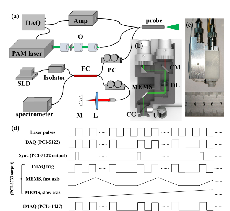
Figure 1(a), 1(b), and 1(c) show the layout of the system, the volumetric rendering of the handheld probe, and the photograph of an assembled probe, respectively. In ORPAM, 532nm laser pulses with a duration of 8ns emanating from a high repetition-rate (10KHz) laser (FQS-200-1-Y-532, Elforlight) are coupled to a single mode fiber (460HP, Nufern) by an objective (GCO-2112, Daheng Optics) after passing through a spatial optical filter. The light is collimated using an adjustable fiber collimator (CFC-8X-A, Thorlabs Inc.), reflected by a coated prism and a customized cold mirror, and focused by a doublet lens (GCL-010601, 0.1NA, Daheng Optics). The focused beam is reflected via another prism and scanned by a MEMS mirror (WM-LS_5, WiO Tech), which has a 2mm mirror plate. The laser beam passes through two cover glasses (CG), a water cube and a sealing membrane (SM) to illuminate the sample. The induced photoacoustic signals are reflected by the cover glass tilted with an angle of 45° in the water cube and captured using a flat ultrasonic transducer (XMS-310-B, Olympus), which has a center frequency of 10MHz, −6dB bandwidth of 60% and a 2mm active area. The captured signals are amplified by a homemade 62dB amplifier and digitized using a data acquisition card (PCI-5122, National Instruments) at a sampling rate of 100MS/s.
Fig. 1.
The schematic of the handheld ORPAM-OCT system and volumetric rendering of the imaging probe. (a) The schematic of the system configuration. O, Objective lens; FC, 2 × 2 fiber coupler; PC, fiber polarization controller; L, convex lens; M, reference mirror. (b) 3-D rendering of the handheld probe. CM, cold mirror; DL, doublet lens; CG, cover glass; UT, ultrasonic transducer. (c) Photograph of the handheld probe with a size of 65 mm × 30 mm × 18 mm. (d) The synchronization and trigger sequences for dual-modality imaging.
The OCT unit employs a superluminescent diode (SLD-371, SUPERLUM) with a center wavelength of 839.8nm and a full width at half-maximum (FWHM) bandwidth of 51.8nm. The light is coupled to a 2 × 2 fiber coupler (TW850R5A2, Thorlabs Inc.) after passing through the isolator. Light beam in reference arm is collimated by a collimator (F260APC-780, Thorlabs Inc.), focused by a convex lens (GCL-010605, Daheng Optics) and finally reflected by a refection mirror. In the sample arm, the light is collimated by an adjustable collimator (CFC-8X-B, Thorlabs Inc.) to compensate the optical chromatic dispersion. The adjusted sample beam passes through the cold mirror and is merged with the ORPAM light path. Two fiber-based polarization controllers (FPC023, Thorlabs Inc.) are added into both reference and sample arms to adjust the light polarization. The reflected interference light signals are detected by a homemade spectrometer consisting of a doublet collimator (F810APC-780, Thorlabs Inc.), a 1200-line grating, a doublet lens with a focal length of 30 mm (GCL-010604, Daheng Optics), a line scan camera (spl4096-140km, Basler) with an exposure time of 60μs, and a high-speed frame grabber board (PCIe-1427, National Instruments).
For each ORPAM-OCT experiment, we collected 500 A-lines to form a B-scan and 500 B-scans to reconstruct a 3D image. As shown in Fig. 1(d), the output synchronization signal generated by the pulsed laser is used to trigger the data acquisition card (PCI-5122) of ORPAM that generates a start trigger signal to synchronize the multifunctional data acquisition card (PCI-6733, National Instruments). The multifunctional data acquisition card outputs four triangle waveforms ranged from 1V to 5V to drive the MEMS mirror and one square wave sequence to synchronize the frame grabber card (PCIe-1427) of OCT.
2.2 Phantom preparation
We imaged the sharp edge of a surgical blade to evaluate the spatial resolutions and a carbon fiber phantom consisting of numerous carbon fibers on the top surface. The blade and the carbon fibers were embedded in a tissue mimicking background phantom with a given optical absorption coefficient of 0.01mm−1 and a reduced scattering coefficient of 1.0mm−1 by mixing agarose, intralipid, and India ink.
2.3 Animals preparation
Mice were freely laid down on a heating pad which was used to maintain the body temperature at 37°C after anaesthetizing with chloral hydrate (50mg/kg) by intraperitoneal injection. The hairs of mouse ears were gently removed. All the procedures have been approved by Southern University of Science and Technology.
2.4 Human experiments
We imaged the oral cavity of a male volunteer. The volunteer wore a protection glass to avoid the potential damage of laser beams to the eyes during the experiments. He sat on a chair and the technician held the probe and adjusted it in order to align the imaging window with the selected region inside the oral cavity. After the experiments, the dentist inspected the imaged region for three days and no obvious damage was observed. We have obtained the written consent form from the volunteer before the experiment.
2.5 Laser safety
For ORPAM, considering that the size of the optical focus is 3.7μm and the measured photon energy after the focusing lens is ~80nJ, the excitation photon energy is calculated as ~700mJ/cm2 at the optical focus in air. When we designed the probe, the imaging plane was adjusted to be ~0.25mm beneath the tissue surface. Therefore, the photon density on the tissue surface is calculated as ~3.5mJ/cm2 which is much lower than the American National Standards Institute (ANSI) safety limit of 22mJ/cm2 at 532 nm. For OCT, the incident laser power on the tissue surface is 4mW, which is below the optical damage threshold of skin imaging at 850nm [25].
3. Results and discussion
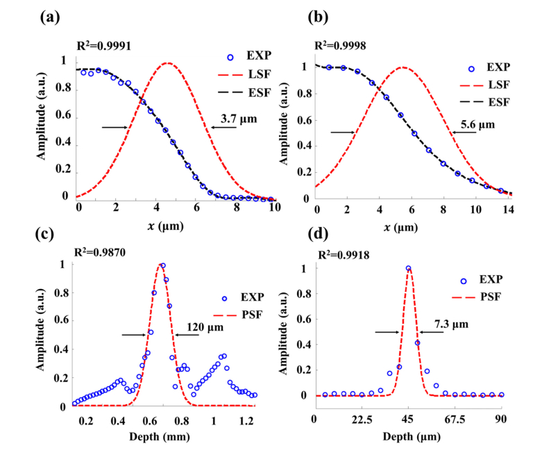
We collected 1000 depth-resolved ORPAM and OCT signals (A-scans) of the sharp edge. As shown in Figs. 2(a) and 2(b), the raw signals were normalized (blue dots) and fitted (black lines) to derive the edge spread functions (ESFs) of the system. We derived the line spread functions (LSFs, red dashed lines in Figs. 2(a) and 2(b)) from ESFs for both ORPAM and OCT to estimate the lateral resolutions. The full width at half maxima (FWHM) of each LSF was calculated as the lateral resolution. The lateral resolutions of ORPAM and OCT are measured as 3.7μm and 5.6μm, respectively. Compared with the theoretical values of 3.25μm and 5.06μm, both resolutions deteriorate because of the curvature of the MEMS mirror plate (~5 m in radius) and the mismatches of the reflective indices in the light path. It is feasible to partially compensate the dispersion using a numerical dispersion compensation technique [24].
Fig. 2.
Spatial resolutions of the handheld microscope. (a) The raw data, fitted edge spread function (ESF) and derived line spread function (LSF) of the blade edge (ORPAM). (b) The raw data, fitted edge spread function (ESF) and derived line spread function (LSF) of the blade edge (OCT). (c) The raw data and fitted profile of a Hilbert-transformed A-line (ORPAM). (d) The fitted point spread function (PSF) of a mirror surface (OCT).
Figure 2(c) presents the Gaussian-fitted profile (red dotted lines in Fig. 2(c)) of a Hilbert-transformed A-line signal of ORPAM (blue dots in Fig. 2(c)). The axial resolution of ORPAM is estimated to be 120μm through calculating the FWHM of the fitted A-line. Considering that the axial resolution of ORPAM is positively proportional to the center frequency and bandwidth of the transducer, it is feasible to improve the axial resolution by using a high frequency transducer with a broader bandwidth. For OCT, a mirror surface serves as a perfect reflector to evaluate the axial resolution. Figure 2(d) shows the Gaussian-fitted profile (PSF, red dotted lines in Fig. 2(d)) of an OCT A-line signal (blue dots in Fig. 2(d)). The axial resolution is measured as 7.3μm which is slightly worse than the theoretical value of 5.9μm. The measured sensitivity of OCT is 96 dB.
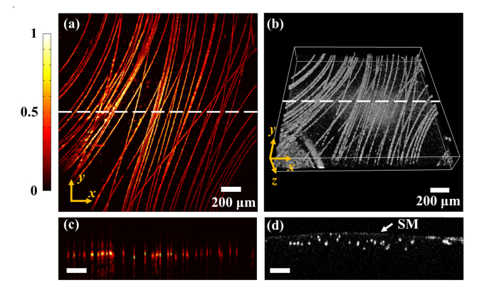
We conducted dual-modality imaging of the carbon fiber phantom and mouse ears to further evaluate the performance of the handheld probe. Figures 3(a) and 3(b) present the ORPAM maximum amplitude projection (MAP) image and OCT 3-D rendering image of the carbon fiber phantom. We imaged the same region of 2 × 2 mm2 in the phantom. Figures 3(c) and (d) show the ORPAM and OCT B-scans along the white dotted line in Figs. 3(a) and 3(b).
Fig. 3.
ORPAM and OCT imaging results of carbon fibers. (a) The maximum amplitude projection (MAP) ORPAM image of carbon fibers. (b) The 3-D rendering of carbon fibers imaged by OCT. (c) The selected ORPAM B-scan along the white dotted line in (a). (d) The selected OCT B-scan along the white dotted line in (b), SM, sealing membrane.
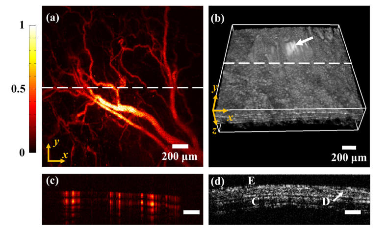
Figures 4(a) and 4(b) present the ORPAM MAP image and OCT 3-D rendering of a mouse ear. Figures 4(c) and 4(d) show the ORPAM and OCT B-scans along the white dotted line in Figs. 4(a) and 4(b). The animal results suggest that ORPAM is capable of visualizing large, medium, small and even cellular-level blood vessels in a mouse ear. As the complementary information, OCT is able to distinguish volumetric structures of the mouse ear including epidermis, dermis and cartilage (Fig. 4(d)). The signals in the region indicated by the white arrow (Fig. 4(b)) are saturated due to the strong reflection of the sealing plastic membrane. Although both ORPAM and OCT have the depth-solving capability, the axial resolution of ORPAM is much worse than that of OCT.
Fig. 4.
Dual modality imaging results of a mouse ear. (a) The maximum amplitude projection (MAP) image of the mouse ear (ORPAM). (b) The 3-D rendering of the mouse ear (OCT). (c) A typical ORPAM B-scan along the white dotted line in (a). (d) A typical OCT B-scan along the white dotted line in (b), E, epidermis; D, dermis; C, cartilage.
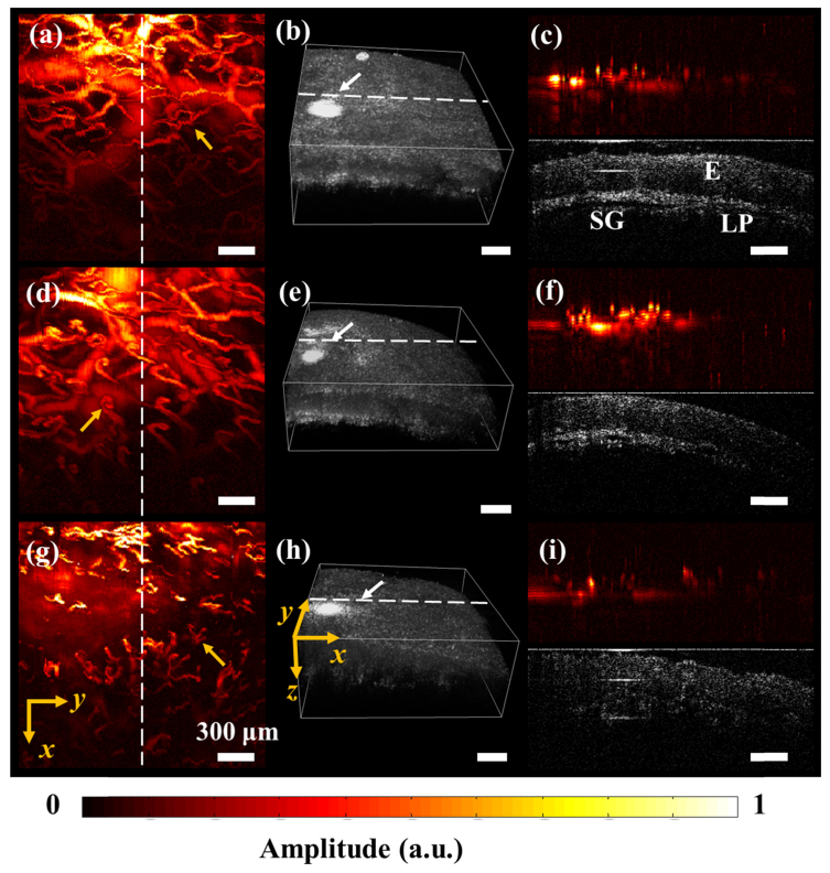
Previously, we have reported the use of a portable ORPAM/ORPAM-OCT for human oral imaging [10, 22]. However, limited by the bulky size, it is only feasible to carry out imaging of certain areas in the human oral cavity. Furthermore, it is hard to hold the probe for a long time. By using a new MEMS-based optical scanner, we have achieved dual-modality handheld probe, which is more suitable for human oral imaging. Figures 5(a), 5(d) and 5(g) show the MAP images of the vasculatures in the lower lip, upper lip and bottom surface of a tongue. Large, medium and small vessels as well as the capillaries are clearly reconstructed, especially the capillary loops indicated by the yellow arrows in Fig. 5(a), (d) and (g). Figures 5(b), 5(e) and 5(h) present the OCT 3-D images obtained from the same region of the oral mucosa, which depict the morphological features of the mucosa. A shown in Figs. 5(c), 5(f) and 5(i), cross-sectional images of vasculature and major structures of oral mucosa such as epidermis, salivary gland and lamina propria are clearly visualized. In clinic, the changes in both microvasculature and tissue structures are tightly associated with human diseases such as oral cancer [26–28], ulcer [29], hemorrhagic shock [30], and cardiac disease [31]. For example, the capillary loops, which connects the venule and arteriole and supplies the oxygen and nutrition exchanges between the red blood cells and other tissue cells, will bend and twist at the early stage of oral cancer [26, 27]. The proposed dual-modality imaging technique is not only able to capture the capillary loops, but also capable of visualizing the morphological features of the tissue, which demonstrate its clinical translational feasibility.
Fig. 5.
In vivo human oral imaging. (a) The MAP image of vasculatures in a human lower lip (ORPAM). (b) 3D image of oral mucosa in the same region of a human lower lip (OCT) with (a). (c) ORPAM and OCT B-scans along the white dotted line in (a) and (b), E, Epidermis; SG, salivary gland; LP, lamina propria. (d) The MAP image of vasculatures in a human upper lip (ORPAM). (e) 3D image of oral mucosa in the same human upper lip (OCT). (f) ORPAM and OCT B-scans along the white dotted line in (d) and (e). (g) The MAP image of vasculatures in bottom surface of a human tongue (ORPAM). (h) 3D rendering of the superficial structures of the same region in the human tongue (OCT). (i) ORPAM and OCT B-scans along the white dotted line in (g) and (h). Scale bar, 300μm.
4. Conclusion
Most of current ORPAM-OCT systems suffer from bulky size. With the use of a miniaturized flat ultrasonic transducer and a 2D MEMS scanner, we propose a dual-modality handheld microscope integrating ORPAM and OCT. We carried out phantom and animals experiments to evaluate the system and successfully applied the probe to inspect the human oral cavity. It is possible to do further improvement of the imaging probe, making it accessible to more clinical applications. First, some functional parameters such as blood oxygenation, oxygen saturation can be derived by using a tunable ORPAM laser source to achieve multi-wavelength illumination, and the blood velocity can be acquired using the Doppler OCT technique. Second, to cover the entire oral cavity even the alimentary canal, further miniaturization is still necessary. Finally, the imaging speed can be accelerated by using a higher repetition rate laser source and a faster scanner to avoid motion artifacts.
Acknowledgements
We thank the volunteer for participating in the experiments.
Funding
National Natural Science Foundation of China (NSFC) (61775028, 81571722, 61525401); Startup grant from Southern University of Science and Technology; State International Collaboration Program from Sichuan (2016HH0019).
Disclosure
The authors declare that there are no conflicts of interest related to this article.
References and links
- 1.Liu N., Yang S., Xing D., “Photoacoustic and hyperspectral dual-modality endoscope,” Opt. Lett. 43(1), 138–141 (2018). 10.1364/OL.43.000138 [DOI] [PubMed] [Google Scholar]
- 2.LaRocca F., Nankivil D., DuBose T., Toth C. A., Farsiu S., Izatt J. A., “In vivo cellular-resolution retinal imaging in infants and children using an ultracompact handheld probe,” Nat. Photonics 10(9), 580–584 (2016). 10.1038/nphoton.2016.141 [DOI] [PMC free article] [PubMed] [Google Scholar]
- 3.Antoch G., Vogt F. M., Freudenberg L. S., Nazaradeh F., Goehde S. C., Barkhausen J., Dahmen G., Bockisch A., Debatin J. F., Ruehm S. G., “Whole-Body Dual-Modality PET/CT and Whole-Body MRI for Tumor Staging in Oncology,” JAMA 290(24), 3199–3206 (2003). 10.1001/jama.290.24.3199 [DOI] [PubMed] [Google Scholar]
- 4.Nam T., Park S., Lee S. Y., Park K., Choi K., Song I. C., Han M. H., Leary J. J., Yuk S. A., Kwon I. C., Kim K., Jeong S. Y., “Tumor targeting chitosan nanoparticles for dual-modality optical/mr cancer imaging,” Bioconjug. Chem. 21(4), 578–582 (2010). 10.1021/bc900408z [DOI] [PubMed] [Google Scholar]
- 5.Wang L. V., Hu S., “Photoacoustic tomography: in vivo imaging from organelles to organs,” Science 335(6075), 1458–1462 (2012). 10.1126/science.1216210 [DOI] [PMC free article] [PubMed] [Google Scholar]
- 6.Beard P., “Biomedical photoacoustic imaging,” Interface Focus 1(4), 602–631 (2011). 10.1098/rsfs.2011.0028 [DOI] [PMC free article] [PubMed] [Google Scholar]
- 7.Xu M., Wang L. V., “Photoacoustic imaging in biomedicine,” Rev. Sci. Instrum. 77(4), 041101 (2006). 10.1063/1.2195024 [DOI] [Google Scholar]
- 8.Hu S., Maslov K., Wang L. V., “Second-generation optical-resolution photoacoustic microscopy with improved sensitivity and speed,” Opt. Lett. 36(7), 1134–1136 (2011). 10.1364/OL.36.001134 [DOI] [PMC free article] [PubMed] [Google Scholar]
- 9.Qi W., Jin T., Rong J., Jiang H., Xi L., “Inverted multiscale optical resolution photoacoustic microscopy,” J. Biophotonics 10(12), 1580–1585 (2017). 10.1002/jbio.201600246 [DOI] [PubMed] [Google Scholar]
- 10.Jin T., Guo H., Jiang H., Ke B., Xi L., “Portable optical resolution photoacoustic microscopy (pORPAM) for human oral imaging,” Opt. Lett. 42(21), 4434–4437 (2017). 10.1364/OL.42.004434 [DOI] [PubMed] [Google Scholar]
- 11.Xie Z., Jiao S., Zhang H. F., Puliafito C. A., “Laser-scanning optical-resolution photoacoustic microscopy,” Opt. Lett. 34(12), 1771–1773 (2009). 10.1364/OL.34.001771 [DOI] [PubMed] [Google Scholar]
- 12.Kim C., Favazza C., Wang L. V., “In vivo photoacoustic tomography of chemicals: high-resolution functional and molecular optical imaging at new depths,” Chem. Rev. 110(5), 2756–2782 (2010). 10.1021/cr900266s [DOI] [PMC free article] [PubMed] [Google Scholar]
- 13.Zhang Y. S., Cai X., Yao J., Xing W., Wang L. V., Xia Y., “Non-Invasive and In Situ Characterization of the Degradation of Biomaterial Scaffolds by Volumetric Photoacoustic Microscopy,” Angew. Chem. Int. Ed. Engl. 53(1), 184–188 (2014). 10.1002/anie.201306282 [DOI] [PMC free article] [PubMed] [Google Scholar]
- 14.Chen S. L., Burnett J., Sun D., Wei X., Xie Z., Wang X., “Photoacoustic microscopy: a potential new tool for evaluation of angiogenesis inhibitor,” Biomed. Opt. Express 4(11), 2657–2666 (2013). 10.1364/BOE.4.002657 [DOI] [PMC free article] [PubMed] [Google Scholar]
- 15.Choma M., Sarunic M., Yang C., Izatt J., “Sensitivity advantage of swept source and Fourier domain optical coherence tomography,” Opt. Express 11(18), 2183–2189 (2003). 10.1364/OE.11.002183 [DOI] [PubMed] [Google Scholar]
- 16.Wojtkowski M., Srinivasan V., Ko T., Fujimoto J., Kowalczyk A., Duker J., “Ultrahigh-resolution, high-speed, Fourier domain optical coherence tomography and methods for dispersion compensation,” Opt. Express 12(11), 2404–2422 (2004). 10.1364/OPEX.12.002404 [DOI] [PubMed] [Google Scholar]
- 17.de Boer J. F., Cense B., Park B. H., Pierce M. C., Tearney G. J., Bouma B. E., “Improved signal-to-noise ratio in spectral-domain compared with time-domain optical coherence tomography,” Opt. Lett. 28(21), 2067–2069 (2003). 10.1364/OL.28.002067 [DOI] [PubMed] [Google Scholar]
- 18.Nassif N., Cense B., Park B. H., Yun S. H., Chen T. C., Bouma B. E., Tearney G. J., de Boer J. F., “In vivo human retinal imaging by ultrahigh-speed spectral domain optical coherence tomography,” Opt. Lett. 29(5), 480–482 (2004). 10.1364/OL.29.000480 [DOI] [PubMed] [Google Scholar]
- 19.Zhang E. Z., Povazay B., Laufer J., Alex A., Hofer B., Pedley B., Glittenberg C., Treeby B., Cox B., Beard P., Drexler W., “Multimodal photoacoustic and optical coherence tomography scanner using an all optical detection scheme for 3D morphological skin imaging,” Biomed. Opt. Express 2(8), 2202–2215 (2011). 10.1364/BOE.2.002202 [DOI] [PMC free article] [PubMed] [Google Scholar]
- 20.Song W., Wei Q., Liu T., Kuai D., Burke J. M., Jiao S., Zhang H. F., “Integrating photoacoustic ophthalmoscopy with scanning laser ophthalmoscopy, optical coherence tomography, and fluorescein angiography for a multimodal retinal imaging platform,” J. Biomed. Opt. 17(6), 061206 (2012). 10.1117/1.JBO.17.6.061206 [DOI] [PMC free article] [PubMed] [Google Scholar]
- 21.Zhang X., Zhang H. F., Jiao S., “Optical coherence photoacoustic microscopy: accomplishing optical coherence tomography and photoacoustic microscopy with a single light source,” J. Biomed. Opt. 17(3), 030502 (2012). 10.1117/1.JBO.17.3.030502 [DOI] [PMC free article] [PubMed] [Google Scholar]
- 22.Qin W., Qi W., Jin T., Guo H., Xi L., “In vivo oral imaging with integrated portable photoacoustic microscopy and optical coherence tomography,” Appl. Phys. Lett. 111(26), 263704 (2017). 10.1063/1.5006234 [DOI] [Google Scholar]
- 23.Li L., Rao B., Maslov K., Wang L. V., “Fast-scanning reflection-mode integrated photoacoustic and optical-coherence microscopy,” Proc. SPIE 7564, 75641Z (2010). 10.1117/12.843826 [DOI] [Google Scholar]
- 24.Fercher A., Hitzenberger C., Sticker M., Zawadzki R., Karamata B., Lasser T., “Numerical dispersion compensation for Partial Coherence Interferometry and Optical Coherence Tomography,” Opt. Express 9(12), 610–615 (2001). 10.1364/OE.9.000610 [DOI] [PubMed] [Google Scholar]
- 25.Zabihian B., Weingast J., Liu M., Zhang E., Beard P., Pehamberger H., Drexler W., Hermann B., “In vivo dual-modality photoacoustic and optical coherence tomography imaging of human dermatological pathologies,” Biomed. Opt. Express 6(9), 3163–3178 (2015). 10.1364/BOE.6.003163 [DOI] [PMC free article] [PubMed] [Google Scholar]
- 26.Inoue H., Kaga M., Ikeda H., Sato C., Sato H., Minami H., Santi E. G., Hayee B., Eleftheriadis N., “Magnification endoscopy in esophageal squamous cell carcinoma: a review of the intrapapillary capillary loop classification,” Ann. Gastroenterol. 28(1), 41–48 (2015). [PMC free article] [PubMed] [Google Scholar]
- 27.Takano J. H., Yakushiji T., Kamiyama I., Nomura T., Katakura A., Takano N., Shibahara T., “Detecting early oral cancer: narrowband imaging system observation of the oral mucosa microvasculature,” Int. J. Oral Maxillofac. Surg. 39(3), 208–213 (2010). 10.1016/j.ijom.2010.01.007 [DOI] [PubMed] [Google Scholar]
- 28.Tsai M. T., Lee H. C., Lee C. K., Yu C. H., Chen H. M., Chiang C. P., Chang C. C., Wang Y. M., Yang C. C., “Effective indicators for diagnosis of oral cancer using optical coherence tomography,” Opt. Express 16(20), 15847–15862 (2008). 10.1364/OE.16.015847 [DOI] [PubMed] [Google Scholar]
- 29.Chao C. Y. L., Cheing G. L. Y., “Microvascular dysfunction in diabetic foot disease and ulceration,” Diabetes Metab. Res. Rev. 25(7), 604–614 (2009). 10.1002/dmrr.1004 [DOI] [PubMed] [Google Scholar]
- 30.De Backer D., Creteur J., Dubois M. J., Sakr Y., Vincent J. L., “Microvascular alterations in patients with acute severe heart failure and cardiogenic shock,” Am. Heart J. 147(1), 91–99 (2004). 10.1016/j.ahj.2003.07.006 [DOI] [PubMed] [Google Scholar]
- 31.O’Rourke M. F., Safar M. E., “Relationship between aortic stiffening and microvascular disease in brain and kidney: cause and logic of therapy,” Hypertension 46(1), 200–204 (2005). 10.1161/01.HYP.0000168052.00426.65 [DOI] [PubMed] [Google Scholar]


