Abstract
An off-the-shelf, small diameter tissue engineered vascular graft (TEVG) would be transformative to surgeons in multiple subspecialties. Herein, we report the results of a small diameter (ID ≈ 1 mm) vascular graft constructed from resorbable, amino acid-based poly(ester urea) (PEU). Electrospun PEU grafts of two different wall thicknesses (type A: 250 μm; type B: 350 μm) were implanted as abdominal infra-renal aortic grafts in a severe combined immune deficient (SCID)/beige (Bg) mouse model and evaluated for vessel remodeling over 1 year. Significantly, the small diameter TEVG does not rupture or lead to acute thrombogenic events during the intervals tested. The pilot TEVG in vivo shows long term patency and extensive tissue remodeling with type A grafts. Extensive tissue remodeling in type A grafts leads to the development of well-circumscribed neovessels with an endothelial inner lining, a neointima containing smooth muscle cells. However, due to slow degradation of the PEU scaffold materials in vivo, the grafts remain after 1 year. The type B grafts, which have 350 μm thick walls, experience occlusion over the 1 year interval due to intimal hyperplasia. This study affords significant findings that will guide the design of future generations of small diameter vascular grafts.
Keywords: bioresorbable, poly(ester urea), electrospun scaffolds, small diameter TEVG, SCID/Bg mice
Graphical Abstract
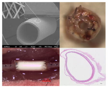
A cell free bioresorbable small diameter vascular graft (ID ≈ 1 mm) is engineered from amino-acid based poly(ester urea) electrospun nanofibers. The pilot study of the graft in an abdominal aortic SCID/Bg mouse model shows long term patency and extensive tissue remodeling over 1 year, leading to the development of well-circumscribed neovessels that mimic native aorta. This study affords significant findings that will guide the design of future generations of small diameter vascular grafts.
1. Introduction
Cardiovascular diseases resulting from arteriosclerosis are the leading cause of death globally.[1] In the United States, more than 500,000 coronary bypass surgeries are performed each year.[2, 3] Autologous grafts from the saphenous vein or the internal mammary artery are the gold standard for arterial bypass surgery.[4, 5] However, the procedures have drawbacks including limited tissue availability, the need for additional surgeries, donor site morbidity, and a ~30% 10-year failure rate.[6] Synthetic vascular grafts, such as those made of expanded polytetrafluoroethylene (ePTFE) and woven or knitted polyethylene terephthalate (PET, Dacron) have been clinically available for quite some time. While clearly innovative solutions, the clinical utility of these synthetic material has been limited to vascular grafts (> 5 mm ID) in areas where the blood flow rate is high and resistance is low. Historically, when applied to small diameter (<5 mm ID) vessel replacements, e.g. coronary bypass surgery, both ePTFE and Dacron show high failure rates due to acute thrombus formation, and chronic anastomotic (excessive tissue formation in adjacent arterial tissue) and/or intimal (excessive tissue ingrowth through the graft wall) hyperplasia.[7–10] These limitations significantly reduce the availability of these approaches to many patient populations who need them. Therefore, development of clinically acceptable small diameter vascular grafts as an alternative to autologous artery or vein substitutes is of significant clinical interest.
Tissue engineered vascular grafts (TEVGs) using resorbable polymers is one of the most promising approaches to address clinical challenges in small diameter vessels. Bioresorbable grafts are analogous to biostable grafts, such as those made of ePTFE or Dacron except one major difference: the polymers used are degradable and allow the neoartery to remodel in vivo.[3, 10, 11] Ideally, the implanted graft should progressively degrade in a timeframe that allows mechanical compensation by extracellular matrix (ECM) deposition and remodeling associated with the natural arterial regeneration process.[12] This approach combines the advantages of a synthetic graft (e.g., availability, manufacturing, sterilization, storage) and the excellent long term performance of natural tissues (e.g., diminished risk of immune rejection, optimal biological and structural properties).[13]
Over the years, substantial work by many groups have utilized synthetic degradable polymers, including poly(lactic acid) (PLA),[14–16] poly(glycolic acid) (PGA),[17–20] poly(caprolactone) (PCL),[12, 21–23] poly(glycerol sebacate) (PGS),[24–27] poly(ester amide)s,[28–31] polyurethanes,[13, 32, 33] natural polymers (e.g. collagen,[34, 35] silk fibroin[36–38]), and their respective copolymers or blends,[39–43] for tissue engineered small diameter vascular grafts. The Breuer and Shinoka lab developed the first tissue engineered small diameter vascular graft to be used in humans.[44–46] This vascular graft is created by seeding autologous bone marrow derived mononuclear cells (BMMCs) onto biodegradable PLLA/PCLA tubular scaffolds and forms a living vascular conduit with the ability to grow, repair and remodel. The first human clinical trial evaluating the use of this TEVG followed.[47–49] Initial results demonstrated an excellent safety profile for the TEVG, again with the additional benefit of growth potential for use in children where somatic overgrowth of non-degradable material is a significant barrier to progress in the field. Moving forward, the same group fabricated a cell-free TEVG for arterial circulation constructed from PCL and reinforced by PLA fiber mesh to enhance cell migration into the scaffolds.[50] The process of vessel remodeling of the TEVG in a mouse abdominal infra-renal aorta model during a 12 month period demonstrated organized neotissue formation. However, due to the uncoordinated scaffold degradation time with new vessel remodeling and the acidic scaffold degradation byproducts, most grafts experienced aneurysmal change and prolonged inflammation. In addition, intimal hyperplasia and graft rupture resulting from mechanical mismatch between implanted grafts and native vessels, acute clotting, and limited tissue regeneration are believed to be responsible for the graft failures.[3, 10] New biodegradable polymers with tunable degradation rate and mechanical properties that can match the remodeling process of a bioresorbable vascular graft in situ are very desirable.
Amino acid based poly(ester urea)s (PEUs) were developed as a new class of bioresorbable polymers.[51–53] In 1997, Katsarava et al. published a synthesis of PEUs via active polycondensation without using diisocyanates.[54] By using a modified version of the process, we have synthesized a series of amino acid based PEUs that showed tunable degradation properties with non-toxic byproducts.[55–61] The mechanical properties, in vitro and in vivo, demonstrated that these materials are suitable candidates for vascular tissue engineering.[61] In this study, PEU derived from L-leucine and 1,10-decanediol, named as poly(1-LEU-10), was used to fabricate porous grafts with very small diameter (ID ≈ 1 mm). Electrospinning was used to fabricate the 1 mm inner diameter grafts as it affords the reliable and consistent generation of fibrous structure that resembles extracellular matrix (ECM) in the native vessel wall with no residual solvent. The structures also support cell infiltration and cellularization of the grafts.[62–65] Small diameter (ID ≈ 1 mm) graft tubes with two different wall thicknesses (i.e. type A: 250 μm; type B: 350 μm) were fabricated. Biomechanical properties of the grafts were measured in vitro. The grafts were then studied in vivo in a SCID/Bg mouse abdominal infra-renal aorta replacement model for long term evaluation. This pilot study aims to develop a cell free resorbable small diameter vascular graft based on electrospun PEU and assess the utility of the TEVG in vivo.
2. Results and Discussion
2.1. Polymer Synthesis and Characterization
The PEU polymer was synthesized from the amino acid L-leucine, 1,10-decanediol, and triphosgene using an interfacial polymerization as described in Figure 1.[56, 58] The chemical structures of the monomer and polymer were confirmed by 1H NMR and 13C NMR spectroscopy (Figure S1 and S2). The molecular mass, molecular mass distribution and thermal properties of the polymer were measured by SEC, DSC and TGA. The data are listed in Table 1. High molecular mass PEU (Mw > 100 kDa) was synthesized using interfacial polymerization. Generally, high molecular mass PEU polymers are required to reproducibly generate fiber or films for biomaterial scaffolds. Furthermore, the degradation temperature (Td, 273 °C) of the Poly(1-LEU-10) material is signficantly higher than the glass transition temperature (Tg, 30 °C), indicating that this material can be melt processed with limited degradation. These characteristics afford high temperature processing techniques such as injection molding and melt processing to be used to process the PEU polymers in addition to electrospinning.
Figure 1.
The two-step synthetic route and characterization data summary of the L-leucine-based PEU (Poly(1-LEU-10)). In the first step, 1 e.q. of 1,10-decanediol is condensed with 2.3 e.q. of L-leucine to yield the monomer. During this step, the amino acids are protonated with p-toluene sulphonic acid to prevent amidation reactions. In the second step, interfacial polycondensation of monomers with triphosgene yields PEU homopolymer.
Table 1.
Characterization data summary for PEU polymer.
| Sample | Mw | ÐM | Td(°C) | Tg(°C) |
|---|---|---|---|---|
| Poly(1-LEU-10) | 135,000 | 1.9 | 273 | 30 |
2.2. Scaffold Characterization
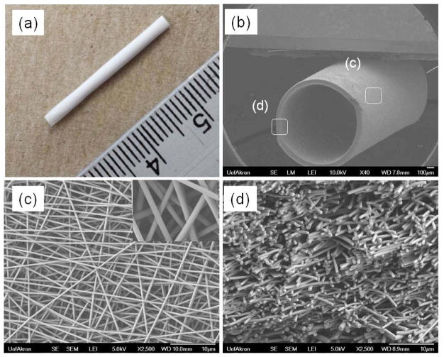
Electrospinning conditions (solution concentration, flow rate, voltage levels, etc.) were optimized in order to obtain uniform bead-free nanofiber morphology prior to collection on a rotating mandrel used for graft fabrication. TEVG scaffolds obtained were cut into 1 mm thick cross-sections and imaged on a field emission SEM (FE-SEM; JSM-7401F, JEOL Ltd., Japan). Fiber diameters at the outer surface and wall thickness were measured using high and low magnification SEM images. Figure 2a shows the gross appearance of the whole electrospun graft. The fabricated grafts were generally 3 cm in length with an inner diameter of approximately 1 mm. Figure 2b shows a tilted view of the graft tube at low magnification SEM. At low magnification, the graft has a round tubular structure. At higher magnification, the surface exhibits a consistent fiber structure (Figure 2c), and at the edge or the graft, cross sections of the fibers appear to be interconnected across the thickness of the graft wall (Figure 2d). The average fiber diameter and pore area were measured by ImageJ and found to be 422 ± 33 nm and 10 ± 4 μm2, respectively. Additionally, the wall thickness of the graft tubes, as determined from SEM images, was found to increase proportionally with the electrospinning collecting time. The wall thicknesses of the TEVG fabricated at different electrospinning collecting times were as follows: 151 ± 27 μm (t = 60 mins), 204 ± 18 μm (t = 90 mins), 255 ± 18 μm (t = 120 mins), 305 ± 15 μm (t = 150 mins) and 348 ± 17 μm (t = 180 mins).
Figure 2.
The gross appearance (a) and SEM images of electrospun poly(1-LEU-10) grafts, (b) entire (×40), (c) surface (×2500), and (d) cross-sectional (×2500) morphologies. Based on the SEM image analysis, the average fiber diameter and pore size are 420 ± 20 nm and 10 ± 4μm2, respectively.
2.3. Biomechanical Properties of Scaffolds
The tensile properties, suture retention strength, and burst pressure were measured on all PEU electrospun TEVG to ensure that they possess significant biomechanical properties to function as vascular grafts. The physical properties of the poly(1-LEU-10) electrospun grafts were summerized in Table 2.
Table 2.
Physical properties summary of Poly(1-LEU-10) electrospun grafts.
| PEU grafts | Image analysis | Tensile testing (n=6) | Suture retention strength (N)(n=6) | Burst pressure (mm Hg) | ||||
|---|---|---|---|---|---|---|---|---|
| Wall thickness (μm) | Fiber diameter (nm) | Pore area (μm2) | Ultimate tensile strength (MPa) | Elastic Modulus (MPa) | Elongation at break (%) | |||
| Type A | 254 ± 20 | 422 ± 33 | 10 ± 4 | 1.7 ± 0.2 | 1.8 ± 0.1 | 598 ± 26 | 8.7 ± 0.4 | > 1000 |
| Type B | 350 ± 18 | 417 ± 28 | 10 ± 4 | 12.0 ± 1.3 | > 1000 | |||
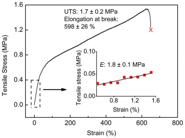
The tensile properties of the electrospun tube scaffolds were studied by uniaxial tensile testing of the whole graft using an Instron 5567 universal tensile testing machine. Using the stress-strain plot (Figure 3), the ultimate tensile strength (UTS), elongation at break, and elastic modulus of Type A PEU grafts (250 μm) were determined. The graft scaffolds showed averaged elastic modulus of 1.8 ± 0.1 MPa, ultimate tensile strength of 1.7 ± 0.2 MPa and elongation at break of 598 ± 26 %. Here, we noticed that the elastic modulus of the PEU grafts fell within the range of the native blood vessels (0.16–12 MPa).[11, 66, 67] This is of great significance, since the close the mechanical properties of grafts come to that of native blood vessels, the less the chance of graft failure due to mechanical property mismatch.[10]
Figure 3.
An engineering stress-strain plot of Type A PEU whole TEVG (250 μm) under wet condition using uniaxial tensile testing. The tensile properties of the PEU grafts were measured using an Instron 3365 universal materials testing machine. The gauge length was 10 mm and the crosshead speed was set at 10 mm min−1. The elastic modulus of the grafts, ultimate tensile stress (UTS) and elongation at break (%) were obtained from the stress-strain curve. Results presented are average values for six individual measurements (n=6). The graft scaffolds showed averaged elastic modulus of 1.8 ± 0.1 MPa, ultimate tensile strength of 1.7 ± 0.2 MPa and elongation at break of 598 ± 26 %.
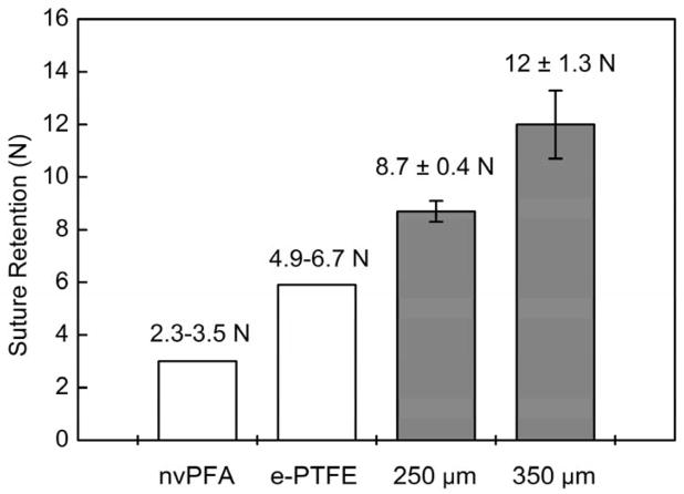
Suture retention strength is essential to evaluate the material for resisting the tension during implantation and it directly relates to the success of the graft implantation procedure. Results analysis as determined by the ultimate tensile strength test (Figure 4) demonstrated the electrospun PEU grafts show sufficiently high enough suture retention strength (Type A: 8.7 ± 0.4 N; Type B: 12.0 ± 1.3 N). Compared with suture strength of native artery (nonviable porcine femoral artery, nvPFA, 2.31–3.51 N) and commonly used vascular graft material (ePTFE, 4.91–6.67 N) as referred from previous published papers,[68] the electrospun PEU grafts showed more than adequate strength for suturing during implantation. Also, there are other previous works reported the suture rentention strength is generally accepted to be greater than 2.0 N.[69]
Figure 4.
Suture retention strength of PEU whole TEVG testing with commercial 5-0 Prolene sutures. Suture retention strength is essential to evaluate the material for resisting the tension during implantation and it directly relates to the success of the graft implantation procedure. The results as determined by the ultimate tensile strength test demonstrated the electrospun PEU grafts show suture retention strength (Type A grafts: 8.7 ± 0.4 N; Type B grafts: 12 ± 1.3 N) that exceed native perfermoral artery and expanded PTFE grafts for implantation.
Burst pressure identified as the maximum pressure that the scaffolds could endure before failure is a crucial factor to determine whether the scaffold material is strong enough to endure physiologic forces and avoid blood leakage.[68] In our study, the limitation of the burst pressure testing machine is 1000 mmHg. As the pressure inside the grafts with continuous water flow increased gradually until it reached the limitation of the machine, the PEU electrospun grafts did not break even after we held the pressure at 1000 mmHg for 30 mins and no leakage was observed.
2.4. In Vitro Results
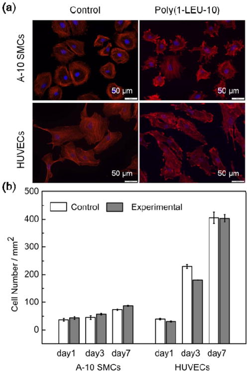
There is little evidence regarding the ability of PEUs to support vascular cell attachment and proliferation, which is a first requirement for their application in vascular tissue engineering. In order to evaluate if the PEU materials are able to support the attachment and spreading of vascular cells, A-10 smooth muscle cells (A-10 SMCs) and human umbilical vein endothelial cells (HUVECs) were seeded on positive control glass coverslips and electrospun PEU covered glass coverslips, both of which are two-dimensional substrates. After 48 hours of culture, immunohistochemical labeling for F-actin and DNA were used to identify the cellular morphology. As shown in Figure 5a, both A-10 SMCs and HUVECs attached and spread on the two-dimensional surface with significant, aligned F-actin expression. Quantification of the cell areas revealed that cells contacting the electospun constructs spread comparably with those cultured on control glass coverslips (Figure S3). This likely means that cells put down focal adhesion contacts and spread on the PEU electrospun nanofibers similar to the way they normally would adhere and spread on glass coverslips. This result suggests that the PEU nanofibers are able to support vascular cell adhesion and spreading in vitro. Since cell adhesion and spreading are the first events that dictate the subsequent cellular responses such as proliferation, migration and matrix deposition,[29] it is important that the PEU nanofibers were able to promote these initial events.
Figure 5.
A-10 smooth muscle cells (A-10 SMCs) and human umbilical vein cells (HUVECs) attachment and proliferation on PEU electrospun nanofibers (cell seed density: 78 mm−2; red: F-actin stained by rhodamine phalloidin; blue: nucleus stained by DAPI). (a) A flat and spread morphology is observed for both cell types up to 48 h culture time, indicating the PEU nanofibers are able to support adhesion of A-10 SMCs and HUVECs in vitro. (b) Cell proliferation of A-10 SMCs and HUVECs cultured in direct contact with electrospun PEU nanofibers after 1, 3 and 7 days of cell seeding, as determined by PrestoBlue assay. The experimental group with PEU electrospun nanofibers showed similar proliferation rates of both cell types to that on the positive glass coverslip controls at day 1, 3 and 7, indicating the PEU nanofibers are able to support proliferation of vascular cells in vitro.
The growth of vascular cells on the nanofibrous scaffolds is another critical issue for their clinical applications. The proliferation of A-10 SMCs and HUVECs on electrospun PEU nanofiber in vitro can provide initial confirmation of the utility of the scaffolds. The growth profiles of A-10 SMCs and HUVECs cultured on the positive control glass coverslips and electrospun PEU covered glass coverslips were measured over a seven-day time course. As shown in Figure 5b, the vascular cells continued to increase in number over the time interval examined on both positive controls and electrospun PEU at similar proliferation rates, indicating that the PEU nanofibers are able to support vascular cell proliferation without producing toxic effects for at least 7 days in vitro.
2.5. In Vivo Animal Study
2.5.1. Survival of The Animals
The survival rate of mice with Poly(1-LEU-10) graft implantation at 24 hours after surgery was 100%. The survival rate at 12 months post-operation was 80% (4/5). One mouse died at 3 months after graft implantation due to a thymus tumor (determined by necropsy) and was not graft related. No long term graft related complications such as graft rupture or aneurysmal dilatation were observed.
2.5.2. Ultrasound and Micro-CT
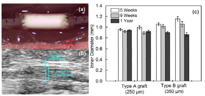
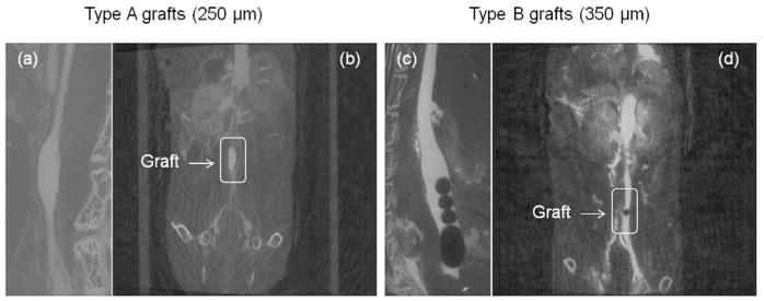
In vivo ultrasound was performed at 5 weeks, 9 weeks and 12 months. All poly(1-LEU-10) grafts demonstrated luminal patency at each time point without evidence of aneurysmal dilatation or stenosis from the ultrasound results (Figure 6b and 6c). However, the inner diameter of the lumen decreased from the 5 week time point to the 12 month time point post-implantation as a consequence of neovessel regeneration. Micro-CT angiography (Figure 7) showed that aneurysmal dilatation or stenosis was absent in Poly(1-LEU-10) type A grafts 12 months after graft implantation, while all type B grafts showed occlusion.
Figure 6.
(a) Intraoperative images of the poly(1-LEU-10) vascular grafts during surgical implantation. (b) A serial doppler ultrasound examination was performed on all of the implanted grafts. All grafts remained patent to the experimental end point according to the ultrasound tests. (c) Graft inner diameter change was calculated by ImageJ software.
Figure 7.
In vivo micro computed tomography (CT) angiography was performed at 12 months. Type A grafts (250 μm) showed long term patency at the time point 12 months ((a) and (b)); Type B grafts (350 μm) demonstrated occlusion ((c) and (d)).
2.5.3. Histological Assessment
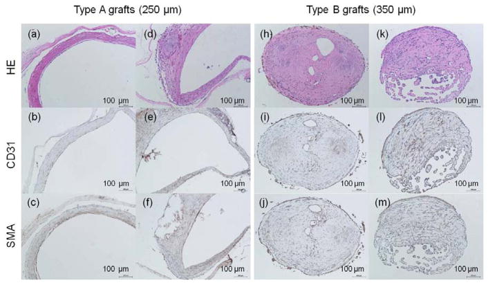
Histological assessment was further performed on all harvested poly(1-LEU-10) grafts after 12 months to evaluate the neovessel remodeling process. Endothelial cells are the predominant cells in the lumen of the blood vessel walls and are required for the structural and functional integrity of the new blood vessel. In this study, the TEVG were harvested and stained for the presence of CD31 (a marker for endothelial cells). CD31 signatures lined in the lumen of type A grafts after graft implantation at 12 months. This result indicated confluent endothelium layers were formed in the type A graft lumen that can mimic native aorta (Figure 8b and 8e). Smooth muscle cells were defined by the presence of smooth muscle actin (aSMA) staining and were observed in the tunica media which infiltrated and replaced the poly(1-LEU-10) type A grafts (Figure 8c and 8f). When examining the immunohistochemical staining results of type B grafts, well-organized endothelium and smooth muscle layers that were observed in type A grafts are absent. The significantly different new tissue remodeling could explain the long term patency of type A grafts and occlusion of type B grafts after 12 months implantation. However, for vascular grafts that only varied in wall thickness while maintaining the same material composition, elastic mechanical properties, and structure morphology, we did not expect to observe such vastly different results in the animal model study. Future work will include further exploration into the wall thickness and biomechanical effects by testing compliance properties of the two different graft types.
Figure 8.
H&E images of harvested poly(1-LEU-10) grafts at 12 months after implantation (a, d, h, k); Endothelial layer of graft lumen stained by CD31 markers (b, e, i, l); Smooth muscle cells stained by immunohistochemical smooth muscle actin (aSMA) (c, f, j, m). Extensive tissue remodeling in type A grafts leads to the development of well-circumscribed neovessels with an endothelial inner lining, a neointima containing smooth muscle cells. However, this well-organized endothelium and smooth muscle layers were absent in type B grafts.
3. Conclusions
This manuscript described a cell free small diameter (ID ≈ 1 mm) vascular graft engineered from electrospun resorbable poly(ester urea) (PEU). Long term performance in vivo of two types of PEU grafts of different wall thickness (type A: 250 μm; type B: 350 μm) were evaluated in an abdominal infra-renal aortic interposition mouse model over 1 year. Extensive tissue remodeling was observed in all type A grafts, which lead to the development of neovessels that mimics native arteries. However, the type B grafts experienced occlusion over the 1 year interval due to intimal hyperplasia. These results suggest the poly(ester urea) may be a promising material for cell-free tissue engineered small diameter vascular grafts, but further biomechanical investigations will be required to assess the effect of graft wall thickness on the long term performance of the grafts
4. Experimental Section
4.1. Materials and Instrumentation
Materials
Unless listed otherwise, all chemical solvents and reagents were purchased from Sigma-Aldrich or Alfa Aesar and used as received. Chloroform was dried with CaH2 overnight and distilled before use. A-10 SMC cells (CRL-1476, ATCC, Rockville, MD) were maintained for less than 20 passages in Dulbecco’s Modified Eagle’s Medium (DMEM) supplemented with 10 % (v/v) fetal bovine serum (FBS), 100 units mL−1 penicillin, 100 μg mL−1 streptomycin, and 2 mmol L−1 L-glutamine (all from Invitrogen, Carlsbad, CA). HUVEC cells (C2517A, Lonza, Basel, Switzerland) were maintained for less than 20 passages in endothelial growth medium kit (EGM-2 BulletKit, CC-3156 & CC-4176, Lonza, Basel, Switzerland) supplemented with 100 units mL−1 penicillin (Invitrogen, Carlsbad, CA). Rhodamine phalloidin and DAPI (4′, 6-diamidino-2-phenylindole) dyes were also from Invitrogen. Cytoskeleton stabilization (CS) buffer was prepared using 1,4-piperazinediethanesulfonic acid (PIPES, 0.1 M) (Fisher Scientific, Pittsburgh, PA), ethylene glycol-bis(2-aminoethylether)-N, N, N′, N′-tetraacetic acid (EGTA, 1 mM) (Sigma Aldrich, St. Louis, MO), and 4% (w/v) polyethylene glycol (PEG, Mw =8000) (Fisher Scientific, Pittsburgh, PA) in distilled water. The solution was buffered using 1 M hydrochloric acid and 1 M sodium hydroxide solutions as required to obtain a pH of 6.9.
Instrumentation
1H and 13C NMR spectra of the monomer and polymer were obtained on Varian NMRS 500 spectrometers. Chemical shifts were reported in parts per million (δ) and referenced to the chemical shifts of the residual solvent (1H NMR, DMSO-d6 (2.50 ppm); 13C, DMSO-d6 (39.50 ppm)). The following abbreviations were used to explain the multiplicities: s=singlet, d=doublet, t=triplet, br=broad singlet, m=multiplet. FTIR spectrum was recorded on a Shimadzu MIRacle 10 ATR-FTIR spectrometer. Size exclusion chromatography (SEC) analyses was performed using a TOSOH HLC-8320 gel permeation chromatograph using 10 mM LiBr in DMF as eluent at a flow rate of 0.8 mL/min. The column and detector temperatures were maintained at 50 °C. The molecular mass and mass distribution were calculated from a universal calibration based on polystyrene standards. The thermal stability of the polymer was measured using thermogravimetric analysis (TGA, TA Q500) across a temperature range of 0–600 °C at a scanning rate of 20 °C/min under nitrogen. 5% decomposition temperature data was collected. The thermal transition of the polymer was studied by using differential scanning calorimetry (DSC, TA Q2000) from −20 to 120 °C at a scanning rate of 20 °C/min. The glass transition temperature was determined as the midpoint in the second heating cycle of DSC.
4.2. Polymer Synthesis and Characterization
The poly(ester urea) monomer and polymer were prepared following previous methods,[61] as shown in Figure 1. Poly(1-LEU-10): 1H NMR (500 MHz, DMSO-d6, δ): 0.83–0.90 (m, 12H) 1.24 (m, 4H) 1.41–1.44 (m, 4H) 1.51–1.54 (t, 4H) 1.58–1.62 (m, 2H) 2.50 (DMSO) 3.28 (H2O) 3.97–4.01 (m, 4H) 4.11–4.14 (m, 2H) 6.26–6.28 (d, 2H). 13C NMR (500 MHz, DMSO-d6, δ): 22.11, 23.06, 24.72, 25.70, 28.52, 29.04, 29.29, 39.17–40.84 (DMSO-d6), 41.43, 51.51, 64.57, 157.50, 173.84. FT-IR (cm−1): 1740 [-C(CO)-O-], 1640, 1555 [-NH-C(O)-NH-], 3355 [-NH-C(O)-NH-]; Mn = 71 kDa, Mw = 135 kDa. Td = 273 °C, Tg = 30 °C. The characterization data summary of polymer molecular mass and thermal properties is listed in Table 1.
4.3. Graft Fabrication
Vascular grafts were fabricated by electrospinning using a 10 w% PEU solution in hexafluoroisopropanol (HFIP). The electrospinning set-up included a syringe pump, a high voltage supply, and a rotating mandrel. A 10 kV positive voltage was applied to the polymer solution by the power supply. The polymer solution was drawn through a 23 gauge blunt tip needle at a constant flow rate of 1 mL h−1. Polymer fibers were then collected on a grounded rotating mandrel mounted on a homemade stand. The collecting mandrel was a stainless steel rod with approximately 1 mm diameter. The collecting mandrel was pre-coated with sugar solution. The distance between the syringe tip and the mandrel was set as 15 cm and the mandrel rotation rate was 100 rpm. To remove the graft from the mandrel, the graft together with the mandrel was soaked in deionized water for one hour. When the thin layer of sugar was dissolved by water, the graft can be easily removed from the mandrel by gently pulling it from one direction. The obtained grafts were then freeze-dried and stored in clean glass vials for future use. Prior to implantation, the grafts were sterilized by ethylene oxide (ETO) for 24 hours. Two types of PEU grafts with two different wall thicknesses were prepared for implantation (type A: 250 μm; type B: 350 μm).
4.4. Graft Characterization
The electrospun TEVG were characterized using field emission scanning electron microscopy (FE-SEM; JSM-7401F, JEOL Ltd., Japan). Characterization included determining the average fiber diameter and average pore area. For each sample, ten SEM images were analyzed, and at least 50 fibers chosen randomly from across the image were measured manually on each image and quantified using ImageJ software (NIH USA, 2008). Pore areas were also measured by a subjective approximation of surface pores from the SEM images (at least 20 measurements per image). Results are given as mean ± standard deviation. For all of the measurements made from the SEM images, calibration of the ImageJ software was done with the scale bar on each image.
4.5. Biomechanical Evaluations
4.5.1. Tensile Properties
Uniaxial tensile testing of electrospun grafts was performed on 1 mm inner diameter tubular specimens from six different electrospun grafts using an Instron 5567 universal tensile testing machine. After soaking the specimens in PBS for 24 h at 37 °C, tensile properties were measured by clamping a 20 mm long graft in the tensile-testing machine and pulling the samples until failure. The gauge length was set as 10 mm, and the crosshead speed was set at 10 mm min−1. Stress-strain data were reported using the Instron Bluehill software. The data were plotted using Origin 8.1 and the ultimate tensile strength, modulus, and strain at break were calculated. Results presented are average values for three individual measurements.
4.5.2. Suture Retention Strength
Suture retention testing was performed on six 1 mm inner diameter tubular specimens from six different electrospun grafts according to the procedure described in Section 8.8 of the American National Standards Institute (ANSI)/Association for the Advancement of Medical Instrumentation (AAMI) ANSI/AAMI VP20:1994 entitled “Cardiovascular Implants-Vascular Graft Prostheses”[68]: After soaking the grafts in PBS for 24 h at 37 °C, one end of the graft was fixed to the stage clamp of the uniaxial tensile testing machine (Instron 5567, USA) and the other end was connected to another clamp using a loop of a common suture material (5-0 Prolene, Ethicon Inc.) placed 2 mm from the edge of the free end of the graft. The gauge length was set as 20 mm, and the crosshead speed was set at 150 mm min−1 until the suture ripped or the graft failed. Suture retention strength, which was defined as fracture strength, was recorded in Newtons using the Instron Bluehill software.
4.5.3. Burst Pressure Strength
The burst pressure strength for the electrospun TEVG was measured by increasing the pressure within the tubular vascular graft until failure occurred (in our case, the pressure level reached the limitation of the machine before graft failed). Luer-lock needle adapters with matching size of the testing grafts were inserted and fixed by superglue to both ends of the grafts. A pressure transducer catheter which connected to computer was attached to one end of the grafts via the luer-lock needle adapters. A 100 mL pressure syringe was attached to the other end of the grafts. The pressure was gradually increased until reaching the limitation of the machine and the pressure change was recorded on computer.
4.6. Biological Activity Evaluations
For the cell culture studies, PEU nanofibers of identical dimensions were electrospun onto glass coverslips to form two-dimensional structures. The PEU nanofiber covered glass coverslips were then placed into 12-well plates, sterilized by ethylene oxide for 24 hours, and pre-soaked for 4 h in cell culture medium prior to cell seeding. Blank glass coverslips were used as control study. A-10 smooth muscle cells (A-10 SMCs) and human umbilical vein endothelial cells (HUVECs) between passage 10 and 14 were used and seeded directly on the surface of the glass coverslips at a density of 2 × 10⁴ per well. The cell-seeded coverslips were incubated for 4 h to allow cells to adhere to the nanofibers before adding additional cell culture medium to the culture plate. Samples of separate studies were all done in triplicate to assure reproducibility of the results. A-10 SMCs were cultured with Dulbecco’s Modified Eagle’s Medium (DMEM) supplemented with 10% fetal bovine serum (FBS) and 1% penicillin and streptomycin. HUVECs were cultured with EGM™-2 Bulletkit™ (Lonza) with basal medium, growth factors, cytokines, and supplements special for endothelial cells. Both cell types were cultured at 37 °C in a humidified incubator containing 5% CO2 for scheduled time. The cell culture medium was changed every 48 hours.
4.6.1. Cell Viability and Proliferation Study
Cell viability and proliferation were evaluated after 1, 3 and 7 days of cell seeding using PrestoBlue assay. Upon entering a living cell, PrestoBlue® reagent is reduced from resazurin, a blue compound with no intrinsic fluorescent value, to resorufin which is red in color and highly fluorescent. Cell proliferation was assessed by the intensity of red color obtained, which was directly proportional to the metabolic activity of the cell population. At scheduled time points (day 1, 3, and 7), cell culture medium was removed. Cell seeded coverslips were transferred to empty 12-well culture plates and refilled by 1 mL of fresh cell medium containing 10% v/v of PrestoBlue. After 0.5 to 2 h of incubation at 37 °C, 3 × 100 μL of medium was taken from each well to a 96-well plate and analyzed for fluorescence measurement. The fluorescence intensity was measured on a Synergy™ MX plate reader from BioTek at an excitation wavelength of 560 nm and an emission wavelength of 590 nm. The observed fluorescence intensity was then converted to cell numbers according to established calibration curves.
4.6.2. Cell Attachment and Spreading Study
To study cell attachment and spreading on the scaffold material, A-10 SMCs and HUVECs (78 cell/mm2) were seeded directly on the PEU nanofiber covered glass coverslips in 12-well culture plates and cultured for 48 h before fixation. For immunohistochemical staining, cells were fixed using 3.7% paraformaldehyde in CS buffer for 10 min and then permeabilized with 0.5% TritonX-100 for 9 min. Excess formaldehyde was quenched with 0.05% sodium borohydride in PBS. 5% donkey serum in CS buffer was then added and the well plate was incubated at room temperature for 20 min to block the non-specific binding activity. The actin filaments of the cytoskeleton were stained with rhodamine phalloidin (1:200 dilution in PBS) for 1 h. After rinsing three times with PBS, the nucleus was stained with DAPI (1:1000 dilution in PBS) for 20 mins and washed four times with PBS. Coverslips were mounted on microscope slides with mounting medium for fluorescence (Vector Laboratories Inc. Burlingame, CA) and sealed with nail enamel upon drying. Fluorescent pictures were taken using and inverted IX 81 microscope (Olympus, Center Valley, PA) with 10×, 20× and 40× objectives.
4.7. Animal Study
All animals received humane care in compliance with the National Institutes of Health (NIH) Guide for the Care and Use of Laboratory Animals. The Institutional Animal Care and Use Committee (IACUC) at Nationwide Children’s Hospital approved the use of animals and all procedures described in this study. 8-week old female SCID/Bg mice were purchased from Taconic Biosciences (Hudson, NY).
4.7.1. Graft Implantation
Poly(1-LEU-10) grafts were implanted as infra-renal aortic interposition conduits using microsurgical technique (n=5 for each type and timpoint). The mice were anesthetized using ketamine xylazine cocktail with ketoprofen as pre-anesthesia analgesic. The hair in the surgical area was removed by a razor and then disinfected by betadine and alcohol pads. A midline laparotomy incision from below the xyphoid to the suprapubic region was made, and a self-retaining retractor inserted. The intestines were wrapped in saline-moistened gauze and retracted. The infrarenal aorta and inferior vena cava were bluntly defined. Microsurgery was performed using an operating microscope with zoom magnification. The aorta was separated from the inferior vena cava and vascular control was obtained with microvascular clamps and then the infra-renal aorta was transected. A Poly(1-LEU-10) aortic interposition graft was implanted with proximal and distal end-to-end anastomoses using a sterile 10-0 monofilament suture on tapered needles. Any hemorrhage was controlled by applying topical absorbable sterile hemostatic agents (Surgicel). The intestines were returned to the abdominal cavity. The abdominal musculature and skin were closed in two layers using 6-0 prolene suture. The length of the procedure was 35 minutes. Motrin water was provided for 48 hours after surgery. Animals were followed for 9 weeks and 12 months after implantation. Post-operatively, no drugs such as anti-platelet or anti-coagulant agents were used.
4.7.2. Ultrasound
Serial ultrasonography (Vevo Visualsonics 770; Visualsonics, Toronto, ON, Canada) was used to monitor grafts after implantation. Prior to ultrasonography, mice were anesthetized with 1.5% inhaled isoflurane. Graft luminal diameter was determined sonographically at the indicated time points after implantation and patency was determined by measuring flow velocity proximal and distal to the graft.
4.7.3. Contrast-enhanced Micro-CT Angiography
Under anesthesia, in vivo microCT angiography was performed with the GE eXplore Locus in vivo microCT scanner (GE Healthcare, Milwaukee, WI, USA). MicroCT data were acquired with an x-ray source of 70 kVp tube voltage, 32 mA tube current, 4 × 4 detector binning model, 16 milliseconds exposure per frame, 70 gain, and 20 offset for contrast-enhanced CT acquisitions. One minute prior to acquisition, animals were given an intra-jugular 0.3 cc bolus of Ultravist (370 mgI ml−1, Bayer Healthcare, Wayne, NJ). A single frame of 220 projections for 42 seconds of continuous x-ray exposure was used. Volumetric microCT images were reconstructed in a 360 × 185 × 505 format with voxel dimensions of 98.4 × 98.4 × 98.4 μm3 using a Feldkamp algorithm with calibrated Hounsfield units (HU).
Micro-CT data was transferred to the Advanced Workstation (version 4.4; GE Healthcare) for further reconstruction and quantitative analysis. Sites of anastomosis were approximated. Measurements of graft length, inner luminal diameter, and graft volume were performed. Similar measurements were performed on adjacent aortas in mice implanted with grafts as well as in controls having undergone sham operation.
4.7.4. Histology and Immunohistochemistry
Grafts harvested at 12 months were fixed in 4% paraformaldehyde (PFA) and embedded in paraffin. Five-micron thick sections were then stained using standardized technique for hematoxylin and eosin (H&E).
Identification of the endothelium and smooth muscle cells was done by immunohistochemical staining of the paraffin-imbedded explant sections with anti-CD 31 (1:50, Abcam), alpha smooth muscle actin (a-SMA) (Dako, Carpinteria, CA). Antibody binding for CD31 and aSMA was detected using biotinylated anti IgG (1:200, Vector, Burlingame, CA). This was followed by binding of streptavidin-horse radish peroxidase (HRP) and color development with 3,3-diaminobenzidine (DAB).
4.8. Statistical Analysis
Results are expressed as mean ± standard deviation. The statistical significance of differences among time points was analyzed using one-way ANOVA. A probability value of less than 0.05 was considered significant.
Supplementary Material
Acknowledgments
The authors are grateful for financial support from the Akron Functional Materials Center. Drs. Fei Lin, Erin P. Childers, Mary Beth Wade are acknowledged for useful discussions and comments on the manuscript. Additional thanks to Prof. Hossein Tavana in Biomedical Engineering at the University of Akron for the source of HUVECs. Funding from R01HL098228 was used to support this work.
Footnotes
Supporting Information is available from the Wiley Online Library or from the author.
Contributor Information
Dr. Yaohua Gao, Department of Polymer Science, The University of Akron, Akron, Ohio 44325, United States
Dr. Tai Yi, Department of Surgery, Nationwide Children’s Hospital, Columbus, Ohio 43205, United States
Dr. Toshiharu Shinoka, Department of Surgery, Nationwide Children’s Hospital, Columbus, Ohio 43205, United States
Dr. Yong Ung Lee, Department of Surgery, Nationwide Children’s Hospital, Columbus, Ohio 43205, United States
Prof. Darrell H. Reneker, Department of Polymer Science, The University of Akron, Akron, Ohio 44325, United States
Dr. Christopher K. Breuer, Department of Surgery, Nationwide Children’s Hospital, Columbus, Ohio 43205, United States
Prof. Matthew L. Becker, Department of Polymer Science, The University of Akron, Akron, Ohio 44325, United States
References
- 1.Yusuf S, Reddy S, Ôunpuu S, Anand S. Circulation. 2001;104:2855. doi: 10.1161/hc4701.099488. [DOI] [PubMed] [Google Scholar]
- 2.Diodato M, Chedrawy EG. Surgery Research and Practice. 2014;2014:6. doi: 10.1155/2014/726158. [DOI] [PMC free article] [PubMed] [Google Scholar]
- 3.Sell SA, Bowlin GL. J Mater Chem. 2008;18:260. [Google Scholar]
- 4.Canver CC. Chest. 1995;108:1150. doi: 10.1378/chest.108.4.1150. [DOI] [PubMed] [Google Scholar]
- 5.Perera GB, Mueller MP, Kubaska SM, Wilson SE, Lawrence PF, Fujitani RM. Annals of vascular surgery. 2004;18:66. doi: 10.1007/s10016-003-0094-y. [DOI] [PubMed] [Google Scholar]
- 6.Li S, Sengupta D, Chien S. Wiley Interdiscip Rev Syst Biol Med. 2014;6:61. doi: 10.1002/wsbm.1246. [DOI] [PubMed] [Google Scholar]
- 7.Kannan RY, Salacinski HJ, Edirisinghe MJ, Hamilton G, Seifalian AM. Biomaterials. 2006;27:4618. doi: 10.1016/j.biomaterials.2006.04.024. [DOI] [PubMed] [Google Scholar]
- 8.Lovett M, Cannizzaro C, Daheron L, Messmer B, Vunjak-Novakovic G, Kaplan DL. Biomaterials. 2007;28:5271. doi: 10.1016/j.biomaterials.2007.08.008. [DOI] [PMC free article] [PubMed] [Google Scholar]
- 9.Tiwari A, Salacinski H, Seifalian AM, Hamilton G. Cardiovascular Surgery. 2002;10:191. doi: 10.1016/s0967-2109(02)00004-2. [DOI] [PubMed] [Google Scholar]
- 10.Walpoth BH, Bowlin GL. Expert Rev Med Devices. 2005;2:647. doi: 10.1586/17434440.2.6.647. [DOI] [PubMed] [Google Scholar]
- 11.Sell SA, McClure MJ, Barnes CP, Knapp DC, Walpoth BH, Simpson DG, Bowlin GL. Biomed Mater. 2006;1:72. doi: 10.1088/1748-6041/1/2/004. [DOI] [PubMed] [Google Scholar]
- 12.de Valence S, Tille JC, Mugnai D, Mrowczynski W, Gurny R, Möller M, Walpoth BH. Biomaterials. 2012;33:38. doi: 10.1016/j.biomaterials.2011.09.024. [DOI] [PubMed] [Google Scholar]
- 13.Soldani G, Losi P, Bernabei M, Burchielli S, Chiappino D, Kull S, Briganti E, Spiller D. Biomaterials. 2010;31:2592. doi: 10.1016/j.biomaterials.2009.12.017. [DOI] [PubMed] [Google Scholar]
- 14.Koch S, Flanagan TC, Sachweh JS, Tanios F, Schnoering H, Deichmann T, Ellä V, Kellomäki M, Gronloh N, Gries T, Tolba R, Schmitz-Rode T, Jockenhoevel S. Biomaterials. 2010;31:4731. doi: 10.1016/j.biomaterials.2010.02.051. [DOI] [PubMed] [Google Scholar]
- 15.Wang S, Zhang Y, Wang H, Yin G, Dong Z. Biomacromolecules. 2009;10:2240. doi: 10.1021/bm900416b. [DOI] [PubMed] [Google Scholar]
- 16.Tara S, Kurobe H, Maxfield MW, Rocco KA, Yi T, Naito Y, Breuer CK, Shinoka T. Journal of Vascular Surgery. doi: 10.1016/j.jvs.2014.03.011. [DOI] [PubMed] [Google Scholar]
- 17.Hajiali H, Shahgasempour S, Naimi-Jamal MR, Peirovi H. International Journal of Nanomedicine. 2011;6:2133. doi: 10.2147/IJN.S24312. [DOI] [PMC free article] [PubMed] [Google Scholar]
- 18.Roh JD, Nelson GN, Brennan MP, Mirensky TL, Yi T, Hazlett TF, Tellides G, Sinusas AJ, Pober JS, Saltzman WM, Kyriakides TR, Breuer CK. Biomaterials. 2008;29:1454. doi: 10.1016/j.biomaterials.2007.11.041. [DOI] [PMC free article] [PubMed] [Google Scholar]
- 19.Torikai K, Ichikawa H, Hirakawa K, Matsumiya G, Kuratani T, Iwai S, Saito A, Kawaguchi N, Matsuura N, Sawa Y. The Journal of Thoracic and Cardiovascular Surgery. 2008;136:37. doi: 10.1016/j.jtcvs.2007.06.039. [DOI] [PubMed] [Google Scholar]
- 20.Wen SJ, Zhao LM, Wang SG, Li JX, Chen HY, Liu JL, Liu Y, Luo Y, Changizi R. Chinese medical journal. 2007;120:1331. [PubMed] [Google Scholar]
- 21.Gloria A, Causa F, Russo T, Battista E, Della Moglie R, Zeppetelli S, De Santis R, Netti PA, Ambrosio L. Biomacromolecules. 2012;13:3510. doi: 10.1021/bm300818y. [DOI] [PubMed] [Google Scholar]
- 22.Melchiorri AJ, Hibino N, Yi T, Lee YU, Sugiura T, Tara S, Shinoka T, Breuer C, Fisher JP. Biomacromolecules. 2014;16:437. doi: 10.1021/bm501853s. [DOI] [PMC free article] [PubMed] [Google Scholar]
- 23.Zheng W, Wang Z, Song L, Zhao Q, Zhang J, Li D, Wang S, Han J, Zheng XL, Yang Z, Kong D. Biomaterials. 2012;33:2880. doi: 10.1016/j.biomaterials.2011.12.047. [DOI] [PubMed] [Google Scholar]
- 24.Allen RA, Wu W, Yao M, Dutta D, Duan X, Bachman TN, Champion HC, Stolz DB, Robertson AM, Kim K, Isenberg JS, Wang Y. Biomaterials. 2014;35:165. doi: 10.1016/j.biomaterials.2013.09.081. [DOI] [PMC free article] [PubMed] [Google Scholar]
- 25.Lee KW, Wang Y. Journal of visualized experiments: JoVE. 2011 doi: 10.3791/2691. [DOI] [PMC free article] [PubMed] [Google Scholar]
- 26.Motlagh D, Yang J, Lui KY, Webb AR, Ameer GA. Biomaterials. 2006;27:4315. doi: 10.1016/j.biomaterials.2006.04.010. [DOI] [PubMed] [Google Scholar]
- 27.Wu W, Allen RA, Wang Y. Nat Med. 2012;18:1148. doi: 10.1038/nm.2821. [DOI] [PMC free article] [PubMed] [Google Scholar]
- 28.Horwitz JA, Shum KM, Bodle JC, Deng M, Chu CC, Reinhart-King CA. J Biomed Mater Res, Part A. 2010;95A:371. doi: 10.1002/jbm.a.32858. [DOI] [PubMed] [Google Scholar]
- 29.Karimi P, Rizkalla AS, Mequanint K. Materials. 2010;3:2346. [Google Scholar]
- 30.Knight DK, Gillies ER, Mequanint K. Acta Biomater. 2014;10:3484. doi: 10.1016/j.actbio.2014.04.014. [DOI] [PubMed] [Google Scholar]
- 31.Srinath D, Lin S, Knight DK, Rizkalla AS, Mequanint K. J Tissue Eng Regen Med. 2014;8:578. doi: 10.1002/term.1562. [DOI] [PubMed] [Google Scholar]
- 32.van der Lei B, Bartels HL, Nieuwenhuis P, Wildevuur CR. Surgery. 1985;98:955. [PubMed] [Google Scholar]
- 33.Ye SH, Hong Y, Sakaguchi H, Shankarraman V, Luketich SK, D’Amore A, Wagner WR. ACS Applied Materials & Interfaces. 2014;6:22796. doi: 10.1021/am506998s. [DOI] [PubMed] [Google Scholar]
- 34.Boccafoschi F, Habermehl J, Vesentini S, Mantovani D. Biomaterials. 2005;26:7410. doi: 10.1016/j.biomaterials.2005.05.052. [DOI] [PubMed] [Google Scholar]
- 35.Boccafoschi F, Rajan N, Habermehl J, Mantovani D. Macromol Biosci. 2007;7:719. doi: 10.1002/mabi.200600242. [DOI] [PubMed] [Google Scholar]
- 36.Catto V, Farè S, Cattaneo I, Figliuzzi M, Alessandrino A, Freddi G, Remuzzi A, Tanzi MC. Materials Science and Engineering: C. 2015;54:101. doi: 10.1016/j.msec.2015.05.003. [DOI] [PubMed] [Google Scholar]
- 37.Gui L, Boyle MJ, Kamin YM, Huang AH, Starcher BC, Miller CA, Vishnevetsky MJ, Niklason LE. Tissue Engineering Part A. 2014;20:1499. doi: 10.1089/ten.tea.2013.0263. [DOI] [PMC free article] [PubMed] [Google Scholar]
- 38.Lovett M, Eng G, Kluge JA, Cannizzaro C, Vunjak-Novakovic G, Kaplan DL. Organogenesis. 2010;6:217. doi: 10.4161/org.6.4.13407. [DOI] [PMC free article] [PubMed] [Google Scholar]
- 39.Ahn H, Ju YM, Takahashi H, Williams DF, Yoo JJ, Lee SJ, Okano T, Atala A. Acta Biomater. 2015;16:14. doi: 10.1016/j.actbio.2015.01.030. [DOI] [PubMed] [Google Scholar]
- 40.Caves JM, Kumar VA, Martinez AW, Kim J, Ripberger CM, Haller CA, Chaikof EL. Biomaterials. 2010;31:7175. doi: 10.1016/j.biomaterials.2010.05.014. [DOI] [PMC free article] [PubMed] [Google Scholar]
- 41.Han J, Lazarovici P, Pomerantz C, Chen X, Wei Y, Lelkes PI. Biomacromolecules. 2011;12:399. doi: 10.1021/bm101149r. [DOI] [PubMed] [Google Scholar]
- 42.Matsumura G, Nitta N, Matsuda S, Sakamoto Y, Isayama N, Yamazaki K, Ikada Y. PLoS One. 2012;7:e35760. doi: 10.1371/journal.pone.0035760. [DOI] [PMC free article] [PubMed] [Google Scholar]
- 43.Yao Y, Wang J, Cui Y, Xu R, Wang Z, Zhang J, Wang K, Li Y, Zhao Q, Kong D. Acta Biomater. 2014;10:2739. doi: 10.1016/j.actbio.2014.02.042. [DOI] [PubMed] [Google Scholar]
- 44.Brennan MP, Dardik A, Hibino N, Roh JD, Nelson GN, Papademitris X, Shinoka T, Breuer CK. Annals of surgery. 2008;248:370. doi: 10.1097/SLA.0b013e318184dcbd. [DOI] [PMC free article] [PubMed] [Google Scholar]
- 45.Hibino N, Shin’oka T, Matsumura G, Ikada Y, Kurosawa H. The Journal of Thoracic and Cardiovascular Surgery. 2005;129:1064. doi: 10.1016/j.jtcvs.2004.10.030. [DOI] [PubMed] [Google Scholar]
- 46.Matsumura G, Miyagawa-Tomita S, Shin’oka T, Ikada Y, Kurosawa H. Circulation. 2003;108:1729. doi: 10.1161/01.CIR.0000092165.32213.61. [DOI] [PubMed] [Google Scholar]
- 47.Hibino N, McGillicuddy E, Matsumura G, Ichihara Y, Naito Y, Breuer C, Shinoka T. The Journal of Thoracic and Cardiovascular Surgery. 2010;139:431. doi: 10.1016/j.jtcvs.2009.09.057. [DOI] [PubMed] [Google Scholar]
- 48.Shin’oka T, Matsumura G, Hibino N, Naito Y, Watanabe M, Konuma T, Sakamoto T, Nagatsu M, Kurosawa H. The Journal of Thoracic and Cardiovascular Surgery. 2005;129:1330. doi: 10.1016/j.jtcvs.2004.12.047. [DOI] [PubMed] [Google Scholar]
- 49.Shin’oka T, Imai Y, Ikada Y. N Engl J Med. 2001;344:532. doi: 10.1056/NEJM200102153440717. [DOI] [PubMed] [Google Scholar]
- 50.Tara S, Kurobe H, Maxfield MW, Rocco KA, Yi T, Naito Y, Breuer CK, Shinoka T. Journal of Vascular Surgery. 2015;62:734. doi: 10.1016/j.jvs.2014.03.011. [DOI] [PubMed] [Google Scholar]
- 51.Díaz A, del Valle LJ, Tugushi D, Katsarava R, Puiggalí J. Materials Science and Engineering: C. 2015;46:450. doi: 10.1016/j.msec.2014.10.055. [DOI] [PubMed] [Google Scholar]
- 52.Planellas M, Perez-Madrigal MM, del Valle LJ, Kobauri S, Katsarava R, Aleman C, Puiggali J. Polymer Chemistry. 2015;6:925. [Google Scholar]
- 53.Valle LJd, Franco L, Katsarava R, Puiggalí J. AIMS Molecular Science. 2016;3:52. [Google Scholar]
- 54.Kartvelishvili T, Tsitlanadze G, Edilashvili L, Japaridze N, Katsarava R. Macromol Chem Phys. 1997;198:1921. [Google Scholar]
- 55.Li S, Yu J, Wade MB, Policastro GM, Becker ML. Biomacromolecules. 2015 doi: 10.1021/bm501669u. [DOI] [PubMed] [Google Scholar]
- 56.Lin F, Yu J, Tang W, Zheng J, Xie S, Becker ML. Macromolecules. 2013;46:9515. [Google Scholar]
- 57.Policastro GM, Lin F, Smith Callahan LA, Esterle A, Graham M, Sloan Stakleff K, Becker ML. Biomacromolecules. 2015 doi: 10.1021/acs.biomac.5b00153. [DOI] [PubMed] [Google Scholar]
- 58.Stakleff KS, Lin F, Smith Callahan LA, Wade MB, Esterle A, Miller J, Graham M, Becker ML. Acta Biomater. 2013;9:5132. doi: 10.1016/j.actbio.2012.08.035. [DOI] [PubMed] [Google Scholar]
- 59.Yu J, Lin F, Lin P, Gao Y, Becker ML. Macromolecules. 2013;47:121. [Google Scholar]
- 60.Zhou J, Defante AP, Lin F, Xu Y, Yu J, Gao Y, Childers E, Dhinojwala A, Becker ML. Biomacromolecules. 2014;16:266. doi: 10.1021/bm501456g. [DOI] [PubMed] [Google Scholar]
- 61.Gao Y, Childers EP, Becker ML. ACS Biomaterials Science & Engineering. 2015;1:795. doi: 10.1021/acsbiomaterials.5b00168. [DOI] [PubMed] [Google Scholar]
- 62.Liang D, Hsiao BS, Chu B. Adv Drug Delivery Rev. 2007;59:1392. doi: 10.1016/j.addr.2007.04.021. [DOI] [PMC free article] [PubMed] [Google Scholar]
- 63.Ma Z, Kotaki M, Inai R, Ramakrishna S. Tissue engineering. 2005;11:101. doi: 10.1089/ten.2005.11.101. [DOI] [PubMed] [Google Scholar]
- 64.Pham QP, Sharma U, Mikos AG. Tissue engineering. 2006;12:1197. doi: 10.1089/ten.2006.12.1197. [DOI] [PubMed] [Google Scholar]
- 65.Sell SA, McClure MJ, Garg K, Wolfe PS, Bowlin GL. Adv Drug Delivery Rev. 2009;61:1007. doi: 10.1016/j.addr.2009.07.012. [DOI] [PubMed] [Google Scholar]
- 66.Kurane A, Simionescu DT, Vyavahare NR. Biomaterials. 2007;28:2830. doi: 10.1016/j.biomaterials.2007.02.031. [DOI] [PMC free article] [PubMed] [Google Scholar]
- 67.Teng Z, Tang D, Zheng J, Woodard PK, Hoffman AH. J Biomech. 2009;42:2535. doi: 10.1016/j.jbiomech.2009.07.009. [DOI] [PMC free article] [PubMed] [Google Scholar]
- 68.McClure MJ, Sell SA, Simpson DG, Walpoth BH, Bowlin GL. Acta Biomater. 2010;6:2422. doi: 10.1016/j.actbio.2009.12.029. [DOI] [PubMed] [Google Scholar]
- 69.Billiar K, Murray J, Laude D, Abraham G, Bachrach N. Journal of Biomedical Materials Research. 2001;56:101. doi: 10.1002/1097-4636(200107)56:1<101::aid-jbm1074>3.0.co;2-6. [DOI] [PubMed] [Google Scholar]
Associated Data
This section collects any data citations, data availability statements, or supplementary materials included in this article.


