Abstract
Current in vitro 3D culture models lack a vascular system to transport oxygen and nutrients, as well as cells, which is essential to maintain cellular viability and functions. Here, we describe a microfluidic method to generate a perfusable vascular network that can form inside 3D multicellular spheroids and functionally connect to microchannels. Multicellular spheroids containing endothelial cells and lung fibroblasts were embedded within a hydrogel inside a microchannel, and then, endothelial cells were seeded into both sides of the hydrogel so that angiogenic sprouts from the cell spheroids and the microchannels were anastomosed to form a 3D vascular network. Solution containing cells and reagents can be perfused inside the cell spheroids through the vascular network by injecting it into a microchannel. This method can be used to study cancer cell migration towards 3D co-culture spheroids through a vascular network. We recapitulated a bone-like microenvironment by culturing multicellular spheroids containing osteo-differentiated mesenchymal stem cells (MSCs), as well as endothelial cells, and fibroblasts in the device. After the formation of vascularized spheroids, breast cancer cells were injected into a microchannel connected to a vascular network and cultured for 7 days on-chip to monitor cellular migration. We demonstrated that migration rates of the breast cancer cells towards multicellular spheroids via blood vessels were significantly higher in the bone-like microenvironment compared with the microenvironment formed by undifferentiated MSCs. These findings demonstrate the potential value of the 3D vascularized spheroids-on-a-chip for modeling in vivo-like cellular microenvironments, drug delivery through blood vessels, and cellular interactions through a vascular network.
INTRODUCTION
Microvascular circulation is composed of networks of capillary endothelial cells that connect arteries to veins. These vascular networks function to supply nutrients and oxygen and to remove waste products, which is essential to maintain cellular viability and functions in tissues and organs.1–3 Vascular networks also provide gateways for immune surveillance and routes for cancer metastasis. Thus, engineering perfusable vascular networks that can deliver nutrients and cells to 3D cell constructs could be a powerful platform to recapitulate cellular microenvironments and to model physiological cell functions and disease.4–6 Although various types of tissues have been engineered in vitro, only thin tissues or low metabolic cellular constructs have achieved clinical success because of a lack of vasculature.7,8 Large tissues and cell spheroids with a diameter of more than 400 μm need to be vascularized to maintain cellular viability because transport of oxygen and nutrients is limited to a diffusion distance of 200 μm.3 In vitro 3D culture models are very useful to support cellular functions and formation of tissue-like structures;9–13 however, current 3D culture methods do not contain functional vascular networks necessary to deliver nutrients and cells.
Microfluidic methods have been developed to engineer perfusable vascular networks inside microchannels.14–18 Endothelial cells self-generate a 3D perfusable vascular network in a hydrogel embedded within a microfluidic device by co-culturing with lung fibroblasts (LFs) which can induce angiogenesis and support vascular formation.18,19 These vascular networks have open lumina connected to microchannels, which can deliver reagents and cells. Using this technique, we have previously reported a microfluidic system to vascularize a spheroid.20 By the definition of the cellular interaction between LFs in a spheroid and endothelial cells in microchannels, angiogenic sprouts were anastomosed to the spheroid and the microchannels to form a perfusable vascular network. 3D multicellular spheroids have been used as a useful tool to recapitulate in vivo-like microenvironments;21 however, only few studies have reported vascularized spheroid models,20,22 and these are developed to maintain a single spheroid. In this study, we developed a method to vascularize multiple co-culture spheroids to reconstitute a 3D cellular microenvironment with a functional vascular network. Because of diffusion limitations, we used cell spheroids whose diameter is about 400 μm. We demonstrated that this method can be used as a 3D culture model to study cancer cell migration towards co-culture spheroids through a vascular network. We recreated a bone-like microenvironment using multicellular spheroids containing osteo-differentiated mesenchymal stem cells (MSCs) which are known to promote cancer migration.23–26
MATERIALS AND METHODS
Cell culture
The green fluorescent protein expressing human umbilical vein endothelial cells (GFP-HUVECs, Angio-Proteomie) and the red fluorescent protein expressing human umbilical vein endothelial cells (RFP-HUVECs, Angio-Proteomie) were cultured in endothelial cell growth medium-2 (EGM-2, Lonza), and passage 5–7 cells were used for experiments. Human lung fibroblasts (LFs, Lonza) were cultured in fibroblast growth medium-2 (FGM-2, Lonza), and passage 5–7 cells were used for experiments. Human mesenchymal stem cells (MSCs, Lonza) were cultured in mesenchymal stem cell growth medium (MSCGM, Lonza), and passage 5–7 cells were used for experiments. To differentiate MSCs into osteoblast-like cells, MSCs were cultured in osteogenic differentiation medium (Lonza) for 2–3 weeks. GFP-expressing human breast cancer MDA-MD-231 cells27 (kindly provided by Dr. Gary D. Luker, University of Michigan, Ann Arbor) were cultured in Dulbecco's Modified Eagle's Medium (DMEM; Thermo Fisher Science) containing 10% fetal bovine serum (FBS, Thermo Fisher Science), 50 U ml−1 penicillin, and 50 U ml−1 streptomycin (P/S, Thermo Fisher Science). Human promyelocytic leukemia HL-60 cells were provided by the Riken BioResource Center (BRC). HL-60 cells were cultured in RPMI1640 (Thermo Fisher Science) containing 10% FBS, 50 U ml−1 penicillin, and 50 U ml−1 streptomycin.
Multicellular spheroids were prepared with an initial density of 1.25 × 10⁴ cells consisting of 2.5 × 10³ HUVEC, 5.0 × 10³ LFs, and 5.0 × 10³ MSCs and cultured in a 96-well plate with U-shaped bottom wells (Sumitomo Bakelite, Japan) for 2 days before seeding in a microfluidic device. The diameter of each spheroid was about 400 μm (less than 500 μm). Osteo-differentiated MSCs were used instead of MSCs to form a bone-like microenvironment. MSCs and osteo-differentiated MSCs were stained with either CellTracker red CMTPX (2 μM) or CellTracker blue CMAC (20 μM) for 1 h before seeding the cells.
Fabrication of microfluidic devices
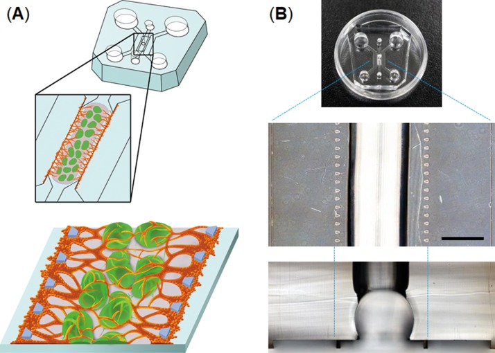
The devices consist of three parallel channels separated by microposts (Fig. 1). The central channel (2 mm wide) is equipped with a semi-cylindrical space (750 μm radius) to hold multiple 3D cell spheroids (typically 30 spheroids). The devices were fabricated from poly(dimethylsiloxane) (PDMS) formed from the prepolymer (Sylgard 184, Dow Corning) at a ratio of 10:1 base to the curing agent using a soft lithographic method. The relief features of the mold were composed of SU-8 2100 (MicroChem) patterns formed on a silicon wafer. The top PDMS layer was formed against relief channel features 200 μm in height. Hydrogel injection ports and the reservoirs for the culture medium were punched out of the PDMS layer with biopsy punches (2 mm for the injection ports, 4 mm for the outlet-reservoirs, and 6 mm for the inlet-reservoirs). The top PDMS layer was bonded with a thin layer of PDMS (200 μm) spin-coated onto a glass cover slip (at 1000 rpm for 60 s) using oxygen plasma treatment for 40 s.
FIG. 1.
Microfluidic device to vascularize 3D cell spheroids. (a) Workflow to generate vascularized 3D cell spheroids-on-a-chip; multiple spheroids are embedded in the center channel using a hydrogel, and then, HUVECs are introduced into the both sides of the hydrogel to form a perfusable vascular network. (b) PDMS microdevice used to form vascularized 3D cell spheroids. The scale bar is 1 mm.
Cell seeding in the microfluidic devices
Multiple spheroids were harvested from a 96-well plate and suspended in a fibrin-collagen gel solution consisting of 2.5 mg ml−1 fibrinogen (Sigma), 0.2 mg ml−1 collagen type I (Corning), 0.15 U ml−1 aprotinin (Sigma), and 0.5 U ml−1 thrombin (Sigma). The solution containing spheroids (typically 30 spheroids) was introduced into the injection port located at the center of the central channel. After polymerization of the fibrin-collagen gel for 15 min incubation, EGM-2 was introduced into both sides of the central microchannel. After 24 h in culture, HUVECs (5.0 × 10⁴ cells in 10 μl EGM-2) were introduced into one side of the microchannel. The device was tilted by 90° and incubated for 30 min to allow the cells to adhere to the surface of a fibrin-collagen gel containing spheroids. This process was repeated for the other side of the microchannel to adhere HUVECs to both sides of the gel (Fig. 1). The reservoirs were filled with EGM-2, and the device was put in an incubator. The microdevices were cultured at 37 °C for up to 14 days with replacement of the medium every other day.
Fluid perfusion of spheroids
To determine whether the vascular networks formed in the devices were perfusable, 10 μM FITC-dextran (70 kDa, sigma) in phosphate-buffered saline (PBS) was introduced into a side-microchannel. To evaluate whether the reconstructed vascular networks can be perfused with blood cells, PBS containing HL-60 cells (1 × 10⁶ cells ml−1) stained with CellTracker red CMTPX (2 μM) was introduced into a side-microchannel (typically 50 μl). The solution was driven by a pressure difference between two side-microchannels.
Evaluation of cancer migration
To monitor cancer migration towards multicellular spheroids, MDA-MB-231 breast cancer cells were introduced into a side-channel in a device in which vascularized spheroids were formed in the central channel and were connected to the side-channel. We evaluated areas occupied by cancer cells in 5 separated areas from the edge of a hydrogel surface to quantify cellular migration rates, and each area indicates 100 μm-wide. Fluorescent images were obtained with an inverted fluorescent microscope (IX81, Olympus), and cellular areas were quantified using cellSens imaging soft (Olympus). Cross-sectional images were obtained using a confocal laser scanning microscope (FluoView FV3000, Olympus) with a 10× or 20× objective lens.
Statistics
Results are reported as mean ± S.E.M. Statistical differences were analyzed by Student's t-test. All statistical evaluation was conducted using a two-tailed t-test, assuming independent samples of normal distribution with equal variance. Significance levels of p < 0.05 and p < 0.005 are denoted in graphs by a single asterisk (*) or double asterisks (**), respectively. Representative results from at least three independent biological replicates are shown.
RESULTS AND DISCUSSION
Engineering of vascular networks into multicellular spheroids
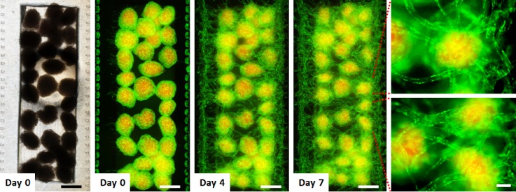
We used the fibrin gel-embedding microfluidic culture platform14 to form perfusable vascular networks. To explore whether vascular networks can be formed with multiple cellular spheroids, we fabricated a PDMS microfluidic device equipped with a semi-cylindrical channel (750 μm in radius) to embed multiple cellular spheroids within a microchannel (Fig. 1). Since large spheroids that exceed 400 μm in diameter are required to be vascularized to maintain their viability,3 we used spheroids with a diameter of c.a. 400 μm to recapitulate a cellular microenvironment. A fibrin-collagen solution containing about 30 multicellular spheroids was injected into the microfluidic device to immobilize spheroids inside a fibrin-collagen gel. HUVECs were injected into both sides of the fibrin-collagen gel (Fig. 2). These spheroids consist of MSCs, HUVECs, and LFs so that LFs induce angiogenesis and HUVECs inside the spheroids can anastomose with sprouts from the side-microchannels. It has been demonstrated that fibroblast-derived matrix proteins and proangiogenic growth factors are essential for endothelial sprouts and lumen formation,28 and thus, fibroblasts are necessary to form vascular networks.29 These initial studies resulted in the formation of a vascular network connected with all the multicellular spheroids and the side-microchannels after 7 days in culture on-chip.
FIG. 2.
Time-lapse images of the formation of a vascular network to connect 3D cell spheroids. The optical image (left) and fluorescent images of cell spheroids with a vascular network in the microfluidic device. Multicellular spheroids consisting of LF, MSCs (red), and GFP-HUVECs (green) were embedded within a fibrin-collagen gel, and then, GFP-HUVECs were seeded into the both sides of the hydrogel. MSCs were labeled with CellTracker red. Fluorescent images show that a vascular network formed to connect individual 3D cell spheroids. The scale bars are 500 and 100 μm for low and high magnification views, respectively.
Characterization of vascular networks formed into multicellular spheroids
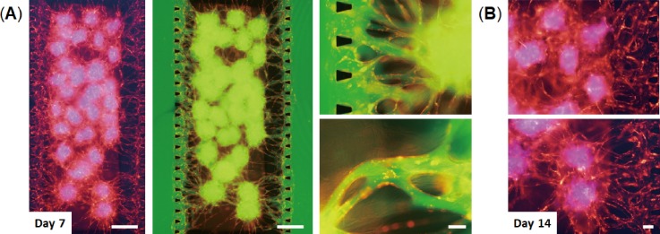
We next tested whether the vascular networks formed in the devices could provide 3D perfusable vessels. Solution containing reagents was introduced into the device in which RFP-HUVECs formed a vascular network through multicellular spheroids after 7 days in culture [Fig. 3(a)]. By injecting FITC-dextran solution inside a side-microchannel, the solution was able to flow through the blood vessels into the other side-microchannel. Fluorescent images clearly show that FITC-dextran solution flowed inside the vessels and the multicellular spheroids without leakage into perivascular space. These results indicate that the vascular networks formed in the devices are perfusable and are able to connect with multicellular spheroids and microchannels. We also confirmed that these vascular networks can maintain their vessel structure for at least 14 days [Fig. 3(b)].
FIG. 3.
Perfusion of the vascular network formed in the device. (a) Vascularized 3D cell spheroids consisting of LF, MSCs (blue), and RFP-HUVECs (red) after 7 days in culture on-chip. FITC-dextran solution (green) was introduced into one side-channel of the device. Fluorescent images show that the vascular network formed in the device is perfusable. The scale bars are 500 and 100 μm for low and high magnification views, respectively. (b) Vascularized 3D cell spheroids after 14 days in culture on-chip. MSCs were labeled with CellTracker blue. The scale bar is 100 μm.
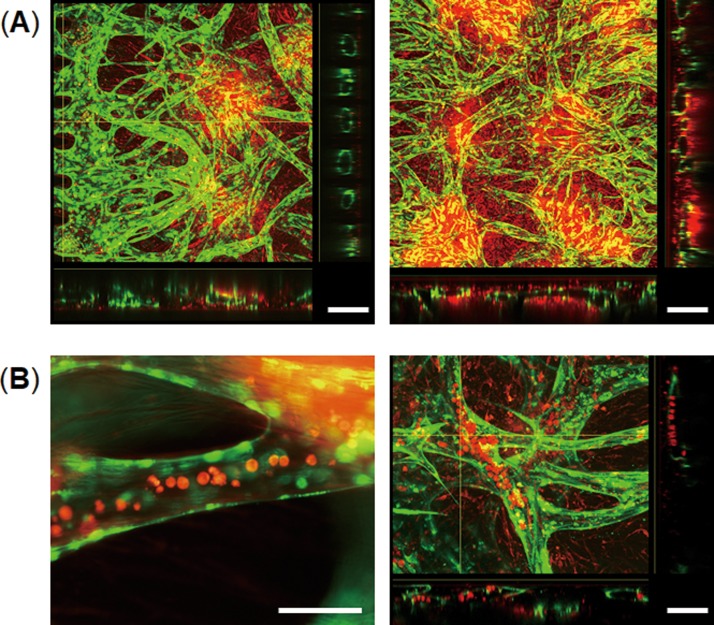
We examined lumen formation of the vascular networks formed in the devices after 7 days in culture by confocal microscopy. The cross-sectional image of the edge of the gel clearly shows that endothelial cells formed an open lumen in each gap between two posts [Fig. 4(a)]. The cross-sectional images of blood vessels indicate the formation of a hollow lumen inside the multicellular spheroids which were labeled with CellTracker red. Thus, the vascular network having perfusable open lumina formed inside multicellular spheroids and connected with the spheroids and the microchannels. We next tested whether the vascular networks formed in the devices can be perfused with cells by injecting HL-60 blood cells labeled with CellTracker red into microchannels. The HL-60 cells were observed inside the blood vessels [Fig. 4(b)] and flowed to the other side-microchannel through the vessels. Thus, this method can form a 3D vascular network connected with multicellular spheroids that can be perfused with cells.
FIG. 4.
Cross-sectional views of the vascular networks formed in the devices. (a) Confocal images of 3D cell spheroids consisting of LF, MSCs (red), and GFP-HUVECs (green) after 14 days in culture on-chip. Cross-sectional views show lumen formation of the vascular network which exists inside the cell spheroids. The scale bar is 200 μm. (b) Introduction of HL-60 blood cells (red) into the vascular network after 14 days in culture on-chip. Cross-sectional views of the blood vessels (right) show intravascular introduction of HL-60 blood cells. HL-60 cells were labeled with CellTracker red. The scale bar is 100 μm.
Modeling of cancer metastasis through a vascular network
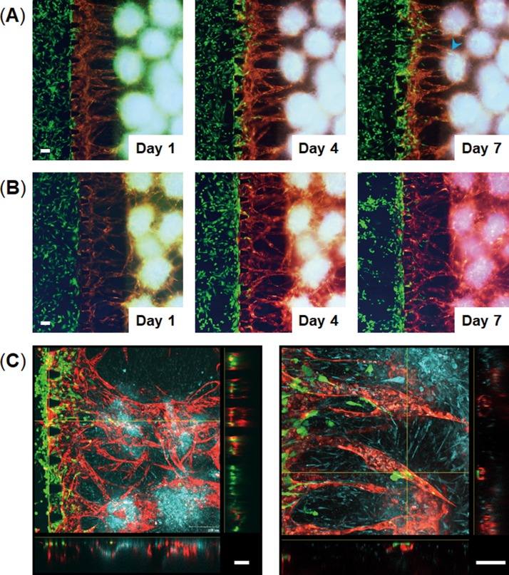
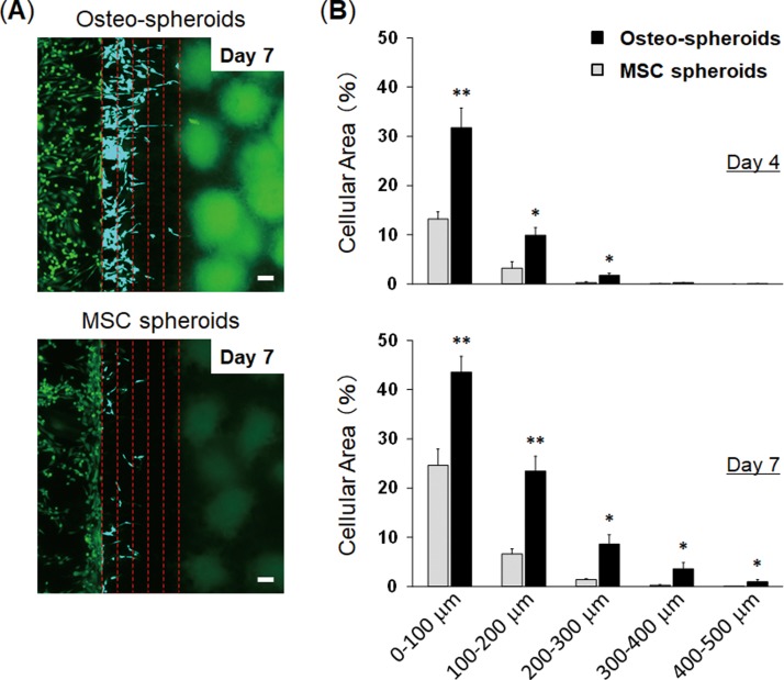
To provide proof-of-concept for the vascularized spheroids-on-a-chip as a platform for evaluating cellular interactions through a vascular network, we evaluated cancer cell migration towards co-culture spheroids through a vascular network. To model cancer metastasis to bone in vitro, we used the MDA-MB-231 metastatic breast cancer cells which are known to migrate towards the bone-mimicking microenvironment generated by osteo-differentiated MSCs.23–26 Kamm's group demonstrated that MDA-MB-231 breast cancer cells extravasated through a vascular network into a bone-mimicking microenvironment which were generated by culturing osteo-differentiated MSCs within a hydrogel.25,26 We used these cells to test whether our method could model cancer metastasis to bone. We engineered a bone-like microenvironment in the microfluidic device using multicellular spheroids consisting of osteo-differentiated MSCs, HUVECs, and LFs (Osteo-spheroids). After 6 days in culture on-chip to form vascularized Osteo-spheroids, GFP-expressing MDA-MB-231 cells were injected into a microchannel connected to a vascular network. The cancer cells exhibited directional migration towards the Osteo-spheroids through the blood vessels, and some of them migrated more than 500 μm to reach the spheroids 7 days after seeding the cancer cells [Fig. 5(a)]. The migration rates of breast cancer cells towards 3D cell spheroids were higher in the bone-like microenvironment compared with the microenvironment formed by undifferentiated MSCs (MSC spheroids) in which less cancer cells were observed inside the blood vessels [Fig. 5(b)]. The cancer cells cultured with the MSC spheroids existed more around the surface of the hydrogels and less inside the blood vessels compared with those cultured with the Osteo-spheroids. The cross-sectional images of the blood vessels demonstrated that cancer cells adhered to the vessels, and most of them migrated inside the blood vessels and eventually extravasated to the Osteo-spheroids [Fig. 5(c)]. We quantified migration rates of cancer cells toward spheroids by measuring the area occupied with the cancer cells which indicates the number of cells [Fig. 6(a)]. When the cancer cells were cultured with the Osteo-spheroids for 4 days on-chip, the number of cells in the blood vessels was significantly higher within 300 μm from the edge compared to those cultured with the MSC spheroids [Fig. 6(b)]. After 7 days in culture, the number of cancer cells in the blood vessels cultured with the Osteo-spheroids was significantly higher within 500 μm from the edge compared to those cultured with the MSC spheroids. These results indicate that more cancer cells entered inside blood vessels and migrated through the blood vessels toward 3D cell spheroids in the bone-like microenvironment compared with the microenvironment generated by undifferentiated MSC spheroids. It has been demonstrated that osteo-differentiated MSCs secrete higher levels of chemokines including CCL230 and CXCL525 compared with undifferentiated MSCs. These chemokines are known to promote migration of breast cancer cells.30,31 Thus, this method was able to model cancer metastasis to bone based on chemokines secreted by 3D cell spheroids through a vascular network.
FIG. 5.
Cancer cell migration toward 3D cell spheroids through a vascular network. MDA-MB-231 breast cancer cells (green) were introduced into the left side channels in the devices in which vascularized spheroids were formed in the central channels. (a) and (b) Time-lapse images of cancer cell migration through blood vessels toward 3D cell spheroids consisting of osteo-differentiated MSCs (blue), LF, and RFP-HUVECs (red) (a) or consisting of undifferentiated MSCs (blue), LF, and RFP-HUVECs (red) (b). Cancer cells migrated through the blood vessels and reached the spheroids containing osteo-differentiated MSCs (blue arrow head) at 7 days following cell seeding. (c) Confocal images of vascularized spheroids containing cancer cells 7 days after seeding the cancer cells. Cross-sectional views show that cancer cells migrated through the vascular network and migrated out of the blood vessels. The scale bar is 100 μm.
FIG. 6.
Evaluation of cancer migration toward 3D cell spheroids. (a) Fluorescent images of GFP-MDA-MB-231 breast cancer cells co-cultured with 3D cell spheroids containing osteo-differentiated MSCs (Osteo-spheroids; top) or undifferentiated MSCs (MSC spheroids; bottom) 7 days after seeding the cancer cells. Red dotted lines indicate the distance from the edge of the center channel containing a fibrin-collagen gel (0–500 μm). We evaluated cellular migration in 5 separated areas to quantify cellular migration, and each line indicates 100 μm-gap. Breast cancer cells within the 5 separated areas are displayed in blue color. (b) Quantification of breast cancer cell migration. Graphs show the percent of area occupied by cancer cells 4 days (top) and 7 days after seeding the cells (bottom). The scale bar is 100 μm. * p < 0.05 and ** p < 0.005. n = 5.
CONCLUSIONS
Organs-on-chips produce key functional units of human organs by recapitulating the tissue architecture and physiological mechanical and biochemical microenvironment.32–34 This technology realizes organ-level cell functions that cannot be recapitulated with conventional in vitro culture methods35–37 and thus has great potential to facilitate drug discovery and development and to model human physiology and diseases. To model complex organ-level cell functions, it is important to recapitulate vascular interfaces of different organs. Engineering perfusable vascular networks that can deliver nutrients and cells to 3D cell constructs could be a powerful platform to recapitulate cellular microenvironments and functions and to study cellular interactions through a vasculature. Here, we present a method to engineer vascularized 3D cell spheroids that contain a perfusable vascular network connected to microchannels. This method enables the formation of perfusable blood vessels formed inside cell spheroids so that solution containing cells and reagents can be delivered inside 3D cell spheroids through blood vessels. We demonstrated that this method can be used to study cancer cell migration through a vascular network by recapitulating a bone-like microenvironment with multicellular spheroids containing osteo-differentiated MSCs. Because this method realizes to generate a perfusable vascular network into 3D cell spheroids, it may be possible to develop vascularized organoids-on-a-chip systems in which organ-like microstructures are connected to blood vessels to transport nutrients and cells. Therefore, this method offers a new approach to recapitulate in vivo-like cellular microenvironments and to study cellular interactions through a vascular network.
ACKNOWLEDGMENTS
We thank Dr. Gary D. Luker (University of Michigan, Ann Arbor) for providing GFP-expressing MDA-MB-231 cells. In addition we wish to give illustration credit to Misaki Ouchida for Fig. 1(A). This work was supported by AMED under Grant No. JP17gm5810008, JSPS KAKENHI Grant Nos. JP16K12874 and JP17H02082, and Hakubi projects of Kyoto University.
References
- 1. Potente M., Gerhardt H., and Carmeliet P., Cell 146, 873–887 (2011). 10.1016/j.cell.2011.08.039 [DOI] [PubMed] [Google Scholar]
- 2. Carmeliet P. and Jain R. K., Nature 473, 298–307 (2011). 10.1038/nature10144 [DOI] [PMC free article] [PubMed] [Google Scholar]
- 3. Auger F. A., Gibot L., and Lacroix D., Annu. Rev. Biomed. Eng. 15, 177–200 (2013). 10.1146/annurev-bioeng-071812-152428 [DOI] [PubMed] [Google Scholar]
- 4. Miller J. S., Stevens K. R., Yang M. T., Baker B. M., Nguyen D.-H. T., Cohen D. M., Toro E., Chen A. A., Galie P. A., Yu X., Chaturvedi R., Bhatia S. N., and Chen C. S., Nat. Mater. 11, 768–774 (2012). 10.1038/nmat3357 [DOI] [PMC free article] [PubMed] [Google Scholar]
- 5. Zhang B., Montgomery M., Chamberlain M. D., Ogawa S., Korolj A., Pahnke A., Wells L. A., Masse S., Kim J., Reis L., Momen A., Nunes S. S., Wheeler A. R., Nanthakumar K., Keller G., Sefton M. V., and Radisic M., Nat. Mater. 15, 669–678 (2016). 10.1038/nmat4570 [DOI] [PMC free article] [PubMed] [Google Scholar]
- 6. Rouwkema J. and Khademhosseini A., Trends Biotechnol. 34, 733–745 (2016). 10.1016/j.tibtech.2016.03.002 [DOI] [PubMed] [Google Scholar]
- 7. Bae H., Puranik A. S., Gauvin R., Edalat F., Carrillo-Conde B., Peppas N. A., and Khademhosseini A., Sci. Transl. Med. 4, 160ps23 (2012). 10.1126/scitranslmed.3003688 [DOI] [PMC free article] [PubMed] [Google Scholar]
- 8. Atala A., Kasper F. K., and Mikos A. G., Sci. Transl. Med. 4, 160rv12 (2012). 10.1126/scitranslmed.3004890 [DOI] [PubMed] [Google Scholar]
- 9. Pampaloni F., Reynaud E. G., and Stelzer E. H. K., Nat. Rev. Mol. Cell Biol. 8, 839–845 (2007). 10.1038/nrm2236 [DOI] [PubMed] [Google Scholar]
- 10. Shamir E. R. and Ewald A. J., Nat. Rev. Mol. Cell Biol. 15, 647–664 (2014). 10.1038/nrm3873 [DOI] [PMC free article] [PubMed] [Google Scholar]
- 11. Nath S. and Devi G. R., Pharmacol. Ther. 163, 94–108 (2016). 10.1016/j.pharmthera.2016.03.013 [DOI] [PMC free article] [PubMed] [Google Scholar]
- 12. Lancaster M. A. and Knoblich J. A., Science 345, 1247125 (2014). 10.1126/science.1247125 [DOI] [PubMed] [Google Scholar]
- 13. Takebe T., Zhang B., and Radisic M., Cell Stem Cell 21, 297–300 (2017). 10.1016/j.stem.2017.08.016 [DOI] [PubMed] [Google Scholar]
- 14. Kim S., Lee H., Chung M., and Jeon N. L., Lab Chip 13, 1489–1500 (2013). 10.1039/c3lc41320a [DOI] [PubMed] [Google Scholar]
- 15. Moya M. L., Hsu Y.-H., Lee A. P., Hughes C. C. W., and George S. C., Tissue Eng., Part C 19, 730–737 (2013). 10.1089/ten.tec.2012.0430 [DOI] [PMC free article] [PubMed] [Google Scholar]
- 16. Kim J., Chung M., Kim S., Jo D. H., Kim J. H., and Jeon N. L., PLoS One 10, e0133880 (2015). 10.1371/journal.pone.0133880 [DOI] [PMC free article] [PubMed] [Google Scholar]
- 17. Sobrino A., Phan D. T. T., Datta R., Wang X., Hachey S. J., Romero-Lopez M., Gratton E., Lee A. P., George S. C., and Hughes C. C. W., Sci. Rep. 6, 31589 (2016). 10.1038/srep31589 [DOI] [PMC free article] [PubMed] [Google Scholar]
- 18. Whisler J. A., Chen M. B., and Kamm R. D., Tissue Eng., Part C 20, 543–552 (2014). 10.1089/ten.tec.2013.0370 [DOI] [PMC free article] [PubMed] [Google Scholar]
- 19. Chen X., Aledia A. S., Popson S. A., Him L., Hughes C. C. W., and George S. C., Tissue Eng., Part A 16, 585–594 (2010). 10.1089/ten.tea.2009.0491 [DOI] [PMC free article] [PubMed] [Google Scholar]
- 20. Nashimoto Y., Hayashi T., Kunita I., Nakamasu A., Torisawa Y., Nakayama M., Takigawa-Imamura H., Kotera H., Nishiyama K., Miura T., and Yokokawa R., Integr. Biol. 9, 506–518 (2017). 10.1039/C7IB00024C [DOI] [PubMed] [Google Scholar]
- 21. Fennema E., Rivron N., Rouwkema J., van Blitterswijk C., and de Boer J., Trends Biotechnol. 31, 108–115 (2013). 10.1016/j.tibtech.2012.12.003 [DOI] [PubMed] [Google Scholar]
- 22. Oh S., Ryu H., Tahk D., Ko J., Chung Y., Lee H. K., Lee T. R., and Jeon N. L., Lab Chip 17, 3405–3414 (2017). 10.1039/C7LC00646B [DOI] [PubMed] [Google Scholar]
- 23. Mastro A. M. and Vogler E. A., Cancer Res. 69, 4097–4100 (2009). 10.1158/0008-5472.CAN-08-4437 [DOI] [PubMed] [Google Scholar]
- 24. Talukdar S. and Kundu S. C., Adv. Funct. Mater. 23, 5249–5260 (2013). 10.1002/adfm.201300312 [DOI] [Google Scholar]
- 25. Bersini S., Jeon J. S., Dubini G., Arrigoni C., Chung S., Charest S. J. L., Moretti M., and Kamm R. D., Biomaterials 35, 2454–2461 (2014). 10.1016/j.biomaterials.2013.11.050 [DOI] [PMC free article] [PubMed] [Google Scholar]
- 26. Jeon J. S., Bersini S., Gilardi M., Dubini G., Charest J. L., Moretti M., and Kamm R. D., Proc. Natl. Acad. Sci. U.S.A. 112, 214–219 (2015). 10.1073/pnas.1417115112 [DOI] [PMC free article] [PubMed] [Google Scholar]
- 27. Torisawa Y., Mosadegh B., Bersano-Begey T., Steele J. M., Luker K. E., Luker G. D., and Takayama S., Integr. Biol. 2, 680–686 (2010). 10.1039/c0ib00041h [DOI] [PMC free article] [PubMed] [Google Scholar]
- 28. Newman A. C., Chou W., Welch-Reardon K. M., Fong A. H., Popson S. A., Phan D. T., Sandoval D. R., Nguyen D. P., Gershon P. D., and Hughes C. C. W., Arterioscler., Thromb., Vasc. Biol. 33, 513–522 (2013). 10.1161/ATVBAHA.112.300782 [DOI] [PMC free article] [PubMed] [Google Scholar]
- 29. Newman A. C., Nakatsu M. N., Chou W., Gershon P. D., and Hughes C. C. W., Mol. Biol. Cell 22, 3791–3800 (2011). 10.1091/mbc.e11-05-0393 [DOI] [PMC free article] [PubMed] [Google Scholar]
- 30. Molloy A. P., Martin F. T., Dwyer R. M., Griffin T. P., Murphy M., Barry F. P., O'Brien T., and Kerin M. J., Int. J. Cancer 124, 326–332 (2009). 10.1002/ijc.23939 [DOI] [PubMed] [Google Scholar]
- 31. Hsu Y. L., Hou M. F., Kuo P. L., Huang Y. F., and Tsai E. M., Oncogene 32, 4436–4447 (2013). 10.1038/onc.2012.444 [DOI] [PubMed] [Google Scholar]
- 32. Huh D., Torisawa Y., Hamilton G. A., Kim H. J., and Ingber D. E., Lab Chip 12, 2156–2164 (2012). 10.1039/c2lc40089h [DOI] [PubMed] [Google Scholar]
- 33. Bhatia S. N. and Ingber D. E., Nat. Biotechnol. 32, 760–772 (2014). 10.1038/nbt.2989 [DOI] [PubMed] [Google Scholar]
- 34. Esch E. W., Bahinski A., and Huh D., Nat. Rev. Drug Discovery 14, 248–260 (2015). 10.1038/nrd4539 [DOI] [PMC free article] [PubMed] [Google Scholar]
- 35. Huh D., Leslie D. C., Matthews B. D., Fraser J. P., Jurek S., Hamilton G. A., Thorneloe K. S., McAlexander M. A., and Ingber D. E., Sci. Transl. Med. 4, 159ra147 (2012). 10.1126/scitranslmed.3004249 [DOI] [PMC free article] [PubMed] [Google Scholar]
- 36. Torisawa Y., Spina C. S., Mammoto T., Mammoto A., Weaver J. C., Tat T., Collins J. J., and Ingber D. E., Nat. Methods 11, 663–669 (2014). 10.1038/nmeth.2938 [DOI] [PubMed] [Google Scholar]
- 37. Benam K. H., Novak R., Nawroth J., Hirano-Kobayashi M., Ferrante T. C., Choe Y., Prantil-Baun R., Weaver J. C., Bahinski A., Parker K. K., and Ingber D. E., Cell Syst. 3, 456–466 (2016). 10.1016/j.cels.2016.10.003 [DOI] [PubMed] [Google Scholar]


