Abstract
We have recently introduced a composite smeared finite element (CSFE) to model gradient-driven mass transport in biological tissue. The transport from capillary system is smeared in a way to transform 1D transport to a continuum, while the tissue is considered as a continuum. Coupling between the smeared pressure and concentration field is achieved through 1D connectivity elements assigned at each FE node. Here we extend our smeared model to include the lymphatic system. The lymphatic vessels are treated in a way analogous to the capillaries, by introducing the corresponding Darcy and diffusion tensors. New connectivity elements are added. In the numerical examples we demonstrate accuracy of the smeared model and the effects of the lymph on the pressure and concentration within extracellular space are evaluated, assuming that there is no transport to the cell space.
Keywords: smeared finite element, convective-diffusive mass transport, biological tissue, capillary system, lymphatic system
1. Introduction
Mass transport from capillaries to tissue and in the reverse direction is a complex process which involves many biophysical parameters. Capillary beds are composed of capillaries of different shape, diameters and transport material parameters, as illustrated in Fig 1. One option to model capillary transport of particles, molecules of nutrients, oxygen and others, is as 1D convective-diffusive process. However, due to capillary net complexity in tissue, and particularly within tumors, it is not feasible to consider each capillary. We have recently introduced a smeared concept and formulated a composite smeared finite element (CSFE) (Kojic et al. 2017), which will be briefly described in the next section. The 1D capillary system is substituted by a continuum, with appropriate transformation of 1D to 2D or 3D governing equations.
Fig. 1.
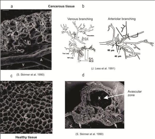
Capillaries within healthy (c) and cancerous tissue (a,b,d) (from (Kojic et al. 2017), according to (Skinner et al. 1990, Less et al. 1991)
Besides the capillaries, there is a net of lymphatic vessels which play important role in the living tissue, acting mainly as a drainage system. A schematic of lymph (from web on Google, figures) is shown in Fig. 2.
Fig. 2.
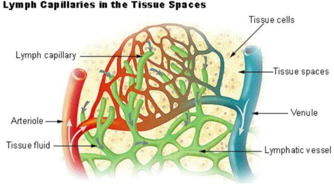
Lymph capillaries within tissue (Schematic from the web, Google)
It is of interest in medical research and in clinical practice to have computational models which are robust and applicable, where the role of lymph can be adequately modeled. In the next section we formulate a finite element which includes the lymphatic system, starting from the previously published composite smeared finite element CSFE (Kojic et al. 2017).
2. Fundamental relations
In our CSFE element (Kojic et al. 2017) we have two domains, capillary and tissue domain. Now we include anther domain belonging to lymphatic system, as shown in Fig. 3.
Fig. 3.
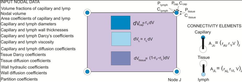
Composite smeared finite element which includes the lymphatic system
The volume fractions occupied by the capillaries, lymph and tissue within the finite element are:
| (1) |
where V is total element volume. In each domain we have pressure and concentration field, therefore the nodal variables are:
| (2) |
In a way analogous to deriving the Darcy and diffusion tensors, we can derive these tensors for the lymphatic system, therefore we have (Kojic et al. 2017):
| (3) |
and:
| (4) |
where for capillaries or lymphatic vessels: dK are diameters, μpipe is viscosity, AK are internal cross-sectional areas of vessels, are directional cosines of vessels, and Atot is total cross-sectional area of all vessels within the element,
| (5) |
The governing incremental-iterative equations for the fluid flow within each of the continuous domains of the element can be written as (for equilibrium iteration i):
| (6) |
where the Darcy matrix is:
| (7) |
and are derivatives of the interpolation functions; P is vector of nodal pressures. The diffusion balance equation of the finite element is (Kojic et al. 2008):
| (8) |
where C is the nodal concentration vector, is the external flux, and matrices and the source vector (evaluated at end of time step) are:
| (9) |
The connectivity elements are introduced for coupling the continuous fields. They are assigned to each element node, connecting capillary and tissue, and tissue with lymph, as shown in Fig. 3. They are fictitious 1D elements with the cross-sectional area calculated as:
| (10) |
where rAV and rAVlymph are the area-to-volume ratios for capillary and lymph, respectively.
Transport through these connectivity elements depend on the hydraulic and diffusive properties of the capillary and lymph vessel walls. The governing equations have the form (6) and (8). For the fluid transport through the wall in equation (6) we have that the matrix for the two-node element is:
| (11) |
where kh is the hydraulic coefficient, and A is the cross-sectional area according to (10). For the diffusion, the incremental balance equation can be written as:
| (12) |
where:
| (13) |
Here, h is the wall thickness, tCJ is concentration at start of time step, and Dwall is the wall diffusion coefficient. Partitioning at the wall surfaces can also be taken into account (Kojic et al. 2015).
3. Examples
We have selected one example generated from geometrical data available on web, and material data according to experimental investigations within Houston Methodist Research Institute (Department for Nanomedicine, coordinator M. Ferrari), and MD Anderson Cancer Center in Houston (coordinator E. J. Koay). The purpose of the example is to demonstrate accuracy of the smeared model with respect to the detailed FE model, and also to show the effects of the lymphatic system on convective-diffusive transport within extracellular space.
A small tissue domain is considered, filled with cells, extracellular space, capillaries and lymph vessels. It is considered that there is no convective and diffusive transport through the domain boundary. The model consists of 5 capillaries (blue), 5 lymph vessels (red), and 70 holes representing cells, hence assumption that transport within cells is not present in this study (Fig. 4). Number of FE nodes in the detailed model is 7563, while number of 2D finite elements in tissue (extracellular space) domain is 6090; and there is 278 1D FE connectivity elements for lymph vessels and capillaries. Total area of diffusion domain is 1521.92 μm2, area of extracellular space is 691.148 μm2. Volume fraction of capillaries is rV = 0.0465, while volume fraction of lymph vessels is rVL = 0.0249. Cells occupy the rest of area, which is 722.12 μm2.
Fig. 4.
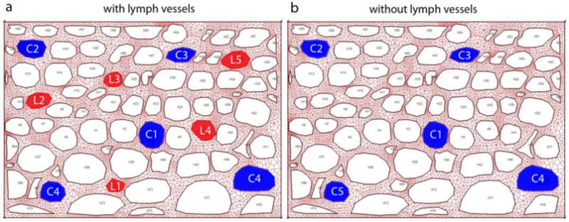
Detailed model of tissue with a) capillaries (blue) and lymph vessels (red); and b) capillaries only. Holes are cells (not modeled).
We adopted in the model that transport characteristics are the same for capillary and lymph vessel walls:
Wall Hydraulic coefficient: 1 μm/(Pa s)
Wall Diffusion coefficient : 1 μm2/s
Diffusion coefficient in extracellular space is 1 μm2/s, and the Darcy coefficient is 1 μm2/(Pa s). Prescribed values in capillaries are P = 1 Pa, C = 1 M, while in lymph vessels we prescribed zero pressure and concentration (P = 0 Pa, C = 0 M).
Correction function according to (Milosevic et al. 2017) is included wall diffusion coefficients, for transport between both capillary-tissue and lymph-tissue domains.
The detailed model and equivalent smeared model are generated with the following characteristics:
100 FE elements and 121 FE nodes
-
Capillaries (5 elements):
Mean diameter: D = 4.24 μm Volume fraction: rV = 0.0465 Wall thickness: δ = 0.5 μm -
Lymph vessels (5 elements):
Mean diameter: D = 3.11 μm Volume fraction: rVL = 0.0249 Wall thickness: δ = 0.5 μm Extracellular space: Volume fraction: rVE = 0.4541 Cells: Volume fraction: rVC = 0.474
It is assumed that there is no transport in cell domain of smeared model, which is in correspondence with true model.
3.1 Model with lymph system
Pressure fields in tissue of true and smeared model are shown in Fig. 5. Mean pressure in tissue of true model is 0.54 Pa, while it is 0.57 Pa in tissue domain of smeared model.
Fig. 5.
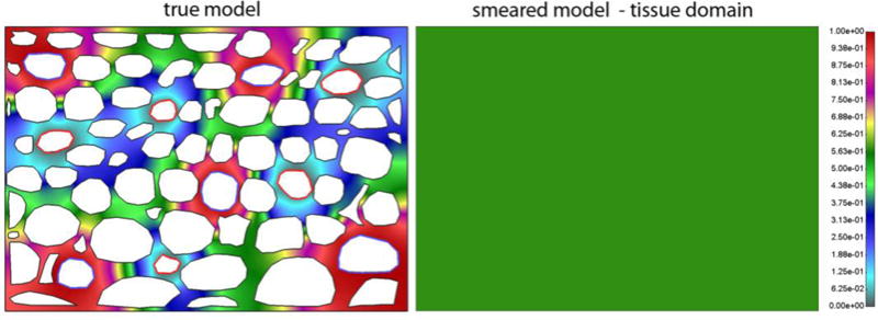
Pressure field in extracellular space for true and smeared model. Since the domain is with impermeable boundaries, the smeared model gives the constant field in the domain.
Velocity field is shown in Fig. 6, and fluid flow occurs from capillaries to tissue and then to lymph vessels.
Fig. 6.
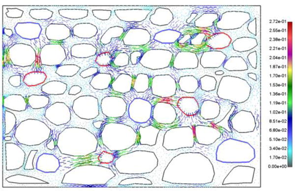
Vector field of velocities in extracellular space at t = 10s
Concentration fields in tissue domain for both true and smeared model, and for two time moments, are shown in Fig. 7.
Fig. 7.
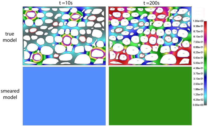
Concentration field in extracellular space for true and smeared model, after t = 10s and t = 200s. Model with capillary and lymphatic system, with constant c = 1 in capillaries. The domain is isolated, and concentration field is constant over the domain for the smeared model.
We further present evolution of the mean concentration of the detailed model and concentration (constant over the domain) obtained by the smeared model. Regarding prescribed concentration in capillaries, we investigated two cases: constant and bolus c(t) prescribed concentration. Smeared model gives reasonably accurate results comparing to the true model, which is shown in Fig. 8a and Fig. 8b, for both cases.
Fig. 8.

Concentration vs. time in extracellular space (tissue) for true and smeared model, with convection included, with a) constant, and b) bolus-type c(t) in capillaries. Concentration in the true model is the mean concentration.
3.2 Model without lymph system
For the model with capillaries only, and with p = 1 Pa prescribed pressure in the capillary lumen, pressure field in tissue is constant with the same p = 1 Pa pressure, while velocities are equal to zero. Since there are no fluid velocities, transport of molecules within tissue occurs due to diffusion only. Concentration fields in tissue are shown in Fig. 9.
Fig. 9.
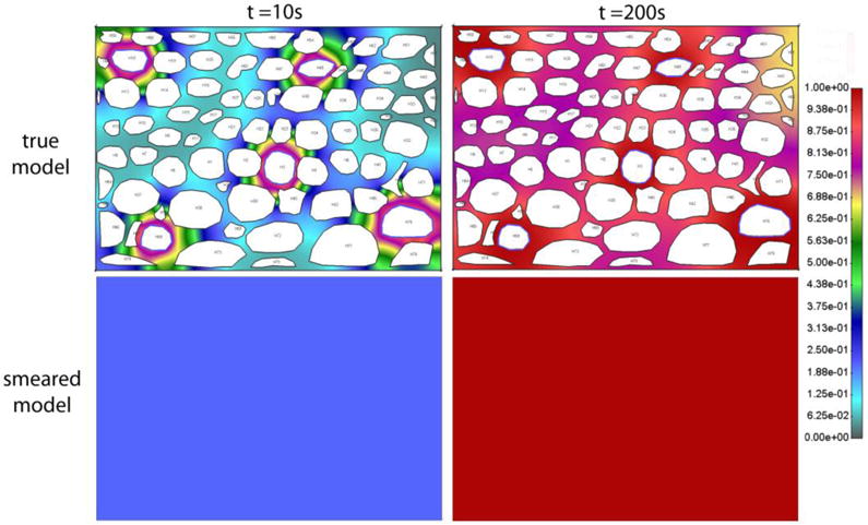
Concentration field after t = 10s and t = 200s, within tissue of true and smeared model, without lymph vessels, and with constant c = 1 prescribed concentration in capillaries.
Evolution of the mean concentration in tissue (true model) and concentration obtained by the smeared model is shown in Fig. 10a and Fig. 10b, for constant c=1 and bolus-type concentration in capillaries. Again, a reasonable agreement between the solutions of the two models is achieved.
Fig. 10.

Concentration vs. Time for true and smeared model, without lymphatic system (there is no convection), for a) constant c(t) and b) bolus c(t) concentration in capillaries.
Influence of lymphatic system can be noticed if we compare results shown in Fig. 7 and Fig. 9, and also comparing diagrams given in Fig. 8 and Fig. 10. Lymphatic system acts as a sink, and in case of c = const. the mean concentration is lower than in case without lymph, and the steady state is reached for approximately two times smaller time period. In case of the bolus c(t), there are slight differences when comparing the shape of the two diagrams, and in the times when the peak is reached.
3.3 Case with concentration and pressure gradients in tissue caused by boundary conditions
In this example, which includes lymphatic system, in addition to already prescribed values at capillaries and lymph vessels, we prescribed different pressures and concentrations in tissue at the two opposite boundaries, in order to generate gradients within the extracellular space. Prescribed values at boundaries are:
c = 1 M, p = 1 Pa at left vertical boundary.
c = 0 M, p = 0 Pa at right vertical boundary.
Mean pressure in tissue domain of true model is 0.5245 Pa, while for smeared model it is 0.5656. Pressure fields in tissue domain for true and smeared model are shown in Fig. 11, and velocity vector field is shown in Fig. 12.
Fig. 11.
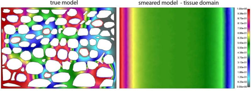
Pressure field for a) detailed (true) model, and b) smeared model. Pressure is prescribed at the left and right boundary and within lymph vessels.
Fig. 12.
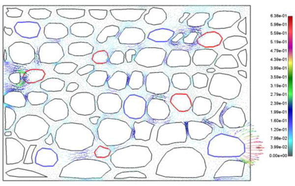
Vector field of velocities at t = 10s, detailed model; boundary conditions as in Fig. 11.
Concentration fields within tissue domain are shown in Fig. 13, while in case without lymph vessels are given in Fig. 14.
Fig. 13.
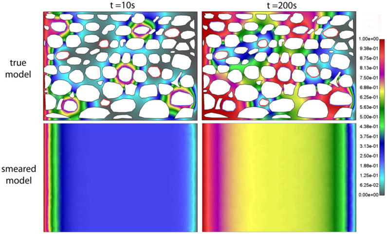
Detailed (true) model and smeared model with prescribed concentrations at the left and right boundary, and in capillaries and lymph vessels. Concentration field after a) t = 10s and b) 200s for model
Fig. 14.
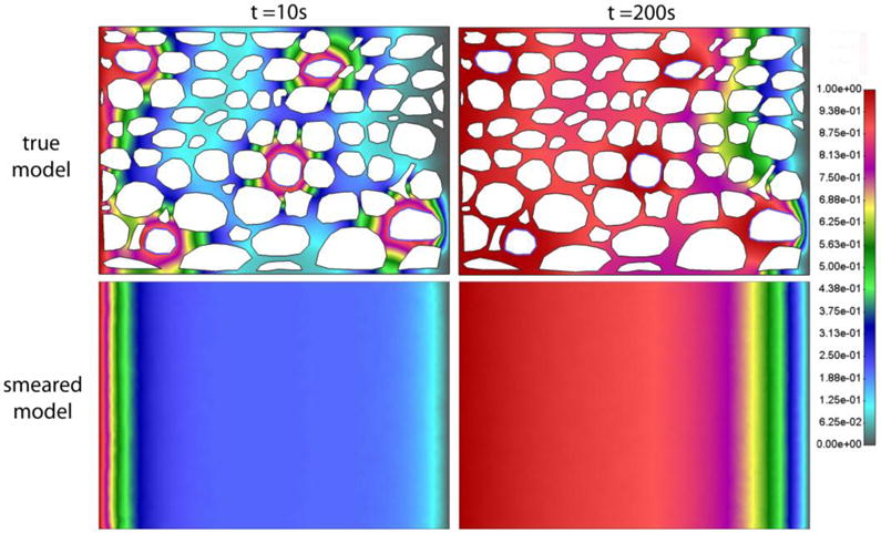
Detailed (true) model and Smeared Model, Concentration field after a) t = 10s and b) 200s for model with capillaries, and with lymphatic system excluded
Diagrams for Concentration vs. Time for this case with concentration gradient are very similar to those in Fig. 8 (not shown here). According to this and figures shown above, we can conclude that the smeared model is applicable to the conditions where there exists a concentration gradient within tissue.
4. Conclusions
We have extended our previously published composite smeared finite element (CSFE) to include lymphatic system. In numerical solutions it was shown that this extended smeared FE gives results enough accurate for practical applications in biomedical research and ultimately in medical practice. Also, the effects of the lymph on pressure and drug concentration within extracellular space are numerically evaluated. The developed finite element, built into our FE package PAK (Kojic et. al, 1998,2017), offers a robust tool for practical use.
Acknowledgments
Dr. Ferrari acknowledges the support from NCI U54 CA210181 and The Ernest Cockrell Jr. Presidential Distinguished Chair at Houston Methodist Research Institute.
The authors acknowledge support from Ministry of Education and Science of Serbia, grants OI 174028 and III 41007, and City of Kragujevac.
References
- Kojic M, Milosevic M, Simic V, Koay EJ, Fleming JB, Nizzero S, Kojic N, Ziemys A, Ferrari M. A composite smeared finite element for mass transport in capillary systems and biological tissue. Comp Meth Appl Mech Engrg. 2017;324:413–437. doi: 10.1016/j.cma.2017.06.019. [DOI] [PMC free article] [PubMed] [Google Scholar]
- Kojic M, Milosevic M, Wu S, Blanco E, Ferrari M, Ziemys A. Mass partitioning effects in diffusion transport. Physical Chemistry Chemical Physics. 2015;17(32):20630–20635. doi: 10.1039/c5cp02720a. [DOI] [PMC free article] [PubMed] [Google Scholar]
- Kojic M, Milosevic M, Wu S, Blanco E, Ferrari M, Ziemys A. Mass partitioning effects in diffusion transport. Physical Chemistry Chemical Physics. 2015;17(32):20630–20635. doi: 10.1039/c5cp02720a. [DOI] [PMC free article] [PubMed] [Google Scholar]
- Kojic M, Slavkovic R, Zivkovic M, Grujovic N, Filipovic N, Milosevic M. PAK-FE program for structural analysis, fluid mechanics, coupled problems and biomechanics. Bioengineering R&D Center for Bioengineering, Faculty of Technical Science; Kragujevac, Serbia: 1998, 2017. [Google Scholar]
- Less JR, Skalak JR, Sevick EM, Jain EM. Microvascular architecture in a mammary carcinoma: Branching patterns and vessel Dimensions. Cancer Research. 1991;51:265–273. [PubMed] [Google Scholar]
- Milosevic M, Simic V, Milicevic B, Koay EJ, Ziemys A, Ferrari M, Kojic M. Correction function for accuracy improvement of the Composite Smeared Finite Element for diffusive transport in biological tissue systems. Comp Meth Appl Mech Engrg. 2017 doi: 10.1016/j.cma.2018.04.012. under review. [DOI] [PMC free article] [PubMed] [Google Scholar]
- Skinner SA, Tutton PJM, O’Brien PE. Microvascular architecture of experimental colon tumors in the rat. Cancer Research. 1990;50:2411–2417. [PubMed] [Google Scholar]


