

Abstract
Study Design
Biomechanical, cadaveric study.
Objective
To compare the fixation strength of a novel S1 pedicle screw insertion technique in a revision setting to a standard S1 pedicle screw and an L5 pedicle screw.
Summary of Background Data
Fusions to the sacrum remain a difficult clinical challenge. Very few salvage techniques exist when a nonunion occurs.
Methods
The biomechanical integrity of three screw fixations, L5 pedicle screws, a standard S1 pedicle screw, and an S1 pedicle screw placed via a superior articulating process entry point (SAP S1), was characterized by performing pullout tests using cadaveric specimens including L5 and sacrum.
Results
SAP S1 constructs (735.5 ± 110.1 N/mm) were significantly stiffer than standard S1 (P = 0.005) and L5 (P = 0.02) constructs. There was no statistically significant difference between the L5 constructs and the standard S1 constructs for linear stiffness. There was no statistical difference between the three fixations for yield load, displacement at yield load, and energy absorbed to yield load.
The ultimate pullout force for the SAP S1 was statistically higher than the standard S1 (1213.7 ± 579.6 vs. 478.6 ± 452.9 N; P = 0.004). Displacement at ultimate load was significantly greater for L5 screw fixation (3.3 ± 1.1 mm) compared to the other two constructs. Both the L5 (2277.4 ± 1873.3 N-mm) and SAP S1 (2628.2 ± 2054.4 N-mm) constructs had significantly greater energy absorbed to ultimate load than the standard S1 construct (811.7 ± 937.6 N-mm), but there was no statistical difference between the L5 and SAP S1 constructs.
Conclusion
S1 pedicle screw fixation via an SAP entry point provides biomechanical advantages compared to screws placed via the standard S1 or L5 entry point and may be a viable option for revision of a failed L5-S1 fusion with a compromised standard S1 entry point.
Level of Evidence
N/A
Lumbar fusions across L5-S1 are frequently performed in the presence of spondylolisthesis or a laminectomy at L5-S1, resulting in instability, spinal pathology affecting L5-S1 (tumor, infection, or fracture), degenerative conditions affecting L5-S1, and spinal deformities.1–5 Unfortunately, there is a relatively high rate of pseudarthrosis associated with L5-S1 fusions (Figure. 1A–C).1–5 This is especially true in long fusions to the sacrum, such as those needed in the treatment of neuromuscular scoliosis, fusions in osteoporotic patients with degenerative scoliosis, and fusions after reduction of spondylolisthesis.1–5 This occurs due to unfavorable biomechanical forces and anatomic constraints of the S1 pedicle. Biomechanically, the L5-S1 level is a transition zone where tremendous loads are transferred, and the oblique orientation of the disc space in this region results in shear forces.6–9 The other disadvantages to pedicle screw fixation at the S1 level relative to other vertebrae include a higher proportion of cancellous bone, relatively shorter pedicle length, and larger pedicle diameter.10,11 All of these factors result in weaker fixation in the S1 pedicle relative to other pedicles in the spine.
Figure 1.

Radiographs of a 52-year-old female who was 18 months status post L5-S1 posterior decompression and instrumented fusion. She continued to have severe back and radiating posterior leg pain. (A) AP radiograph, (B) lateral radiograph, (C) axial CT image showing loosening of the S1 screw. AP indicates anteroposterior.
Various methods have been described to improve lumbosacral fixation. In a biomechanical study by Lebwohl et al,12 the authors performed a biomechanical analysis of various fixation techniques across the lumbosacral junction in six calf spines. In terms of stress-strain, axial compression, and load to failure, the addition of iliac screws provided the best stability across the lumbosacral junction. In a study by Tsuchiya et al,13 the authors performed a retrospective review on 67 patients who underwent long posterior fusions to the sacrum with the use of iliac screws. While they found that iliac screws were effective in decreasing sacral screw failure, there was still a nonunion rate of 5/67 cases. Consequently, finding alternative methods for fixation to the sacrum remains a concern for spine surgeons.
The use of an S1 pedicle screw via a superior articulating process (SAP) entry point may offer spine surgeons another opportunity to fuse across L5-S1 with a new starting point or provide an option for a salvage technique in cases of S1 screw loosening. Therefore, the objective of this study was to evaluate the strength of S1 pedicle screws when placed through the SAP as a salvage technique for S1 screw loosening secondary to pseudoarthrosis. We hypothesized that this new starting point would provide as good a fixation as the standard S1 pedicle screws.
Materials and Methods
Five fresh-frozen cadaveric pelvises with the spine sectioned at the top endplate of L5 (age range: 48–71; three females, two males) were thawed overnight to room temperature for dissection. Skin and nonessential soft tissue elements were dissected while keeping ligaments and bone structure intact. Physiological saline solution was periodically sprayed onto each specimen to avoid desiccation. All specimens were macroscopically normal and none of the specimens had a history of metastatic disease or bone diseases. Additionally, each specimen was visually inspected for gross evidence of previous sacral pathology or instrumentation.
In each specimen, the constructs tested included the following: a standard S1 pedicle screw, bilateral L5 pedicle screws, and an S1 pedicle screw placed via a superior articulating process entry point (SAP S1). The SAP S1 screws were placed after an S1 pedicle screw was placed via a standard starting point and removed to mimic a nonunion. Another standard S1 pedicle screw was placed on the contralateral side to act as an internal control for the SAP S1 screws. L5 pedicle screws were also placed and tested in these same specimens to act as a control for the proper placement of the standard S1 pedicle screws and to give an additional comparison of the stiffness and strength of the SAP S1 screws.
Insertion Technique
Four polyaxial titanium pedicle screws (DePuy Synthes Spine, Inc., Raynham, MA) were placed into each specimen by a board-certified spine surgeon. Screws were placed in the bilateral L5 and S1 pedicles. An awl was first used to break through the dorsal cortex of the spine. Using a pedicle finder, a channel was created through the pedicles. The trajectory was 25° medial and parallel to the endplate for the L5 pedicles. For the S1 pedicles, the trajectory was 30° medial and parallel to the endplate. Then a 5.5-mm tap was used on the same location on the dorsal cortex; 6.5-mm pedicle screws were placed in line with the channel created by the pedicle probe and tap. Screw length was determined to be the length of the channel created when the pedicle finder abutted the cortex of the anterior vertebral body. Screws were placed down until the heads of the screw abutted the cortical bone of the pedicle screw entry point up to a pressure of three-finger tightness. Probing with a pedicle probe and visual inspection of the walls of the pedicle were performed to check for any breaches.
Prior to placement of the SAP screw, one of the already placed S1 screws was randomly chosen to be removed (to simulate screw removal after a nonunion). Then the corresponding inferior half of the inferior articulating process of the L5 vertebrae was removed using a rongeur. In all specimens, the insertion site for the SAP screw was 5-mm medial and 5-mm cephalad from the lateral-caudal edge of the facet joint (Figure 2). In a similar manner as before, an awl was used to break the cortex and a pedicle finder was used to create a new path. The trajectory of this screw was 0° in the medial-lateral plane and parallel to the endplate of the pedicle (Figure 3A, B). The sidedness for placement of the SAP S1 screws was alternated between each successive specimen.
Figure 2.

Starting points for a standard S1 pedicle screw (A) and the SAP S1 screw (B). The insertion site was 5-mm medial and 5-mm cephalad from the lateral-caudal edge of the facet joint. SAP S1 indicates superior articulating process entry point.
Figure 3.
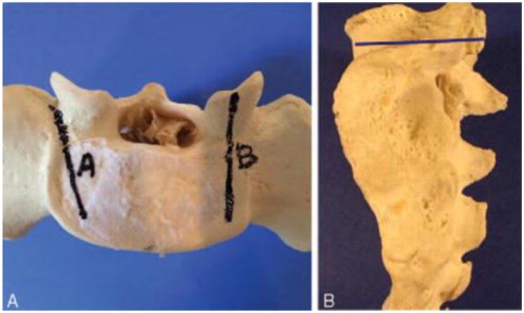
A, The trajectory of the standard pedicle screw (A) and the SAP S1 screw (B) in the axial plane. The trajectory of the SAP S1 screw is 0° to 5° medial in the medial-lateral plane. B, The trajectory of the SAP S1 screw in the sagittal plane is parallel to the endplate of the pedicle (blue line). SAP S1 indicates superior articulating process entry point.
In all the specimens, 6.0 × 45 mm pedicle screws were determined to be the appropriate length and size at L5. For the standard S1 and the SAP S1 screws, 6.0 × 35 mm pedicle screws were used. After placement of the screws, all specimens were visually inspected and no breaches were noted.
Specimen Mounting and Biomechanical Testing
After dissection, the sacroiliac joint was located and an oscillating saw was used to disarticulate the sacrum from the ilium. In order to pot the sacrum in a 13.4 × 9.2 cm metal box, the specimen was transversely cut in the S2-S3 region. Due to variation in size, the same exact location for the transverse cut was not possible for each specimen to fit inside the metal box. Care was taken to not interfere with the placed pedicle screws throughout the mounting process. Additionally, it was necessary to saw off the L5 spinous process in order to accommodate the biomechanical testing setup. The L5 vertebral arch was kept intact throughout this process. The prepared specimen was then potted in the metal box and secured with plaster of Paris (DAP Products Inc., Baltimore, MD). The specimen's anterior vertebral body was potted in a manner that left the posterior aspect exposed and the screw head facing upward.
Biomechanical testing of each bone-screw construct was performed using a screw pullout technique.14,15 The testing setup is depicted in Figure 4. A custom angulation mounting jig was secured to the potted specimen's metal undersurface with two screws and washers. The mounted specimen was then secured onto an x-y translator attached to the baseplate of a material testing system (Instron Model 4411, Instron, Canton MA). The x-y translator comprised two translating plates, one allowed translation in the anteroposterior direction while the other in the mediolateral direction. The combination of the translator and angulation mount allowed uniaxial alignment of the screw of interest with the actuator of the material testing system. A custom screw was rigidly attached to the screw's head and then loaded to a custom actuator attachment. This constrained the top of the custom screw and allowed coupling of pullout force to the specimen.
Figure 4.

Schematic drawing of material testing system setup. Only one pedicle screw is shown in the potted specimen. In actual testing scenarios, three total pedicle screws were inserted as described in the text. A custom angulation mount and the x-y translator allowed uniaxial alignment between the screw and materials testing system actuator.
For biomechanical testing, axial pullout tests were performed. Five N of preload was first applied to each screw followed by a pullout rate of 10 mm/min until failure. Plaster-bone interface was carefully monitored throughout the testing process to ensure that rigid fixation of the anterior vertebral bodies was maintained. Construct testing order was randomized to minimize observational error. The force and displacement data were used to calculate each construct's linear stiffness, yield load and screw displacement, ultimate load and screw displacement, and energy absorbed to yield and ultimate loads (Figure 5). The linear stiffness was measured as the steepest portion of the force-displacement curve. Determination of the yield load was done by pinpointing the load value that corresponded to the first deviation from the force-displacement curve's linear region. Ultimate load was defined as the maximum load each screw managed to sustain prior to complete failure or observation of screw pullout. Energy absorbed was calculated as the area under the force-displacement curve to the displacement corresponding to both yield and ultimate loads.
Figure 5.

Example of a force displacement curve for a superior articulating process entry point (SAP S1) screw during pullout testing. Linear stiffness (N/mm) was defined as the slope of the force displacement curve's linear region. Yield load was defined as the load value that corresponded to the first deviation from the force-displacement curve's linear region. Ultimate load was defined as the maximum load on the curve or observation of screw pullout. Energy absorbed was calculated as the area under the force-displacement curve to the displacement corresponding to both yield and ultimate loads. SAP S1 indicates superior articulating process entry point.
To verify that the screws did not breach the cortical wall, the trajectories were approximated by placing Kirschner wires through remnant holes left by pulled out standard and SAP S1 screws. A sagittal line running through the center of the holes were drawn with a marker. A sagittal section through the line was taken with a band saw so that a section through the standard S1 (Figure 6A) and the SAP S1 (Figure 6B) screw's trajectory was visible. The sectioned bone surface was then cleaned of bone marrow in order to expose the trabecular architecture. A probe was used to determine if the screw had breached through the cortical wall.
Figure 6.

Sagittal sections through the screws trajectories. These were taken after biomechanical testing. The bony walls of the trajectory were probed for any potential breaches. There was noticeably less dense bone surrounding the entry point of the standard S1 construct (A) than the SAP S1 construct (B). Additionally, the trabecular bone surrounding the screw trajectories was noted to be more porous for the standard S1 construct (A). A, Sagittal section through standard S1 construct. B, Sagittal section through SAP S1 construct. SAP S1 indicates superior articulating process entry point.
The mean and standard deviation of the biomechanical parameters were calculated for each construct. Averages of each biomechanical value of the bilateral L5 screws were taken to represent those of the L5 screw for statistical analysis except in one specimen due to specimen mounting failure. Consequently, the L5 values for that specimen were determined based on testing results of one side. The statistical differences between screw locations were obtained using a repeated measures analysis of variance with a P < 0.05 (SigmaPlot, Systat Software Inc., San Jose, CA).
Results
Linear stiffness was significantly higher for the SAP S1 screw fixations compared to both the L5 and S1 constructs (735.5 N/mm [SD: 110.1], 448.8 N/mm [SD: 161.7], and 361.5 N/mm [SD: 300.0], respectively) (Table 1). There were no differences in stiffness between the L5 and standard S1 constructs. There were no significant differences in yield load, displacement at yield load or energy absorbed to yield load between the three constructs (P > 0.079, 0.164, 0.151, respectively) (Table 1).
Table 1.
| Screw | Mean | P VS. | |
|---|---|---|---|
| S1 | SAP S1 | ||
| Linear stiffness (N/mm) | |||
| L5 | 448.8 ±161.7 | 0.559 | 0.020* |
| S1 | 361.5 ±300.0 | 0.005* | |
| SAP S1 | 735.5 ±110.1 | ||
| Yield load (N) | |||
| L5 | 493.8 ±372.3 | 0.079 | 0.976 |
| S1 | 173.5 ±120.8 | 0.058 | |
| SAP S1 | 520.1 ±380.8 | ||
| Ultimate load (N) | |||
| L5 | 928.2 ±593.0 | 0.051 | 0.227 |
| S1 | 478.6±452.9 | 0.004* | |
| SAP S1 | 1213.7±579.6 | ||
| Displacement at yield load (mm) | |||
| L5 | 1.1 ±0.8 | 0.164 | 0.164 |
| S1 | 0.5 ±0.4 | 0.164 | |
| SAP S1 | 0.7 ±0.5 | ||
| Displacement at ultimate load (mm) | |||
| L5 | 3.3 ±1.1 | <0.00* | 0.045* |
| S1 | 2.0±1.0 | <0.001* | |
| SAP S1 | 3.0 ±1.3 | ||
| Energy absorbed to yield load (N•mm) | |||
| L5 | 443.3 ±573.2 | 0.151 | 0.151 |
| S1 | 61.7 ± 71.1 | 0.151 | |
| SAP S1 | 263.4±289.1 | ||
| Energy absorbed to ultimate load (N•mm) | |||
| L5 | 2277.4 ±1873.3 | 0.032* | 0.418 |
| S1 | 811.7 ±937.6 | 0.049* | |
| SAP S1 | 2628.2 ±2054.4 | ||
P<0.05.
SAP S1 indicates superior articulating process entry point; SD, standard deviation.
SAP S1 construct had a significantly greater ultimate load compared to the standard S1 screws (P = 0.004) but not the L5 screws (P = 0.227). Additionally, the ultimate load for the L5 construct was not significantly greater than the standard S1 screws (P = 0.051) (Table 1). Displacements at ultimate load for the L5, S1, and SAP S1 constructs were 3.3 mm (SD: 1.1), 2.0 mm (SD: 1.0), and 3.0 mm (SD: 1.3), respectively (Table 1). The SAP S1 construct had a significantly greater energy absorbed at ultimate load compared to the standard S1 (P = 0.018) and L5 constructs (P = 0.049) (Table 1).
No cortical breaches were detected after sagittal sections were examined through each specimen's standard (Figure 6A) and SAP S1 screw trajectories (Figure 6B). These sections were also visually compared within the same specimen. The cortical bone at the posterior facet of the SAP S1 entry was noted to be thicker than the cortical bone layer of the standard S1 entry point. Additionally, the overall trabecular bone surrounding each screw's trajectory was noted to be denser around the SAP S1 screw than the standard S1 screw.
Discussion
While there are many reasons for the high nonunion rate when the L5-S1 level is fused including unfavorable biomechanical and anatomic factors,10,11 there are few revision strategies when a nonunion occurs across L5-S1. The use of the S1 pedicle screw via an SAP S1 offers spine surgeons another opportunity to fuse across L5-S1 with a new starting point that is just as good if not better than the standard S1 pedicle screw.
Other studies have demonstrated that a more medialized entry point for S1 pedicle screw insertion may have biomechanical advantages relative to the standard method. 14,15 These studies were performed on lumbar vertebrae and the medialized screw had a laterally directed trajectory.14,15 No statistical difference in pullout force and stiffness between the two studied insertion methods was taken to indicate the superiority of the cortical screw in terms of holding strength as it is shorter in length than the standard pedicle screw.14,15 These studies also conducted measurements of bone densitometry, which demonstrated greater bone density along the trajectory of the medialized screw.14,15 Our observation of denser bone surrounding the SAP S1 trajectory in the sagittal sections of the SAP S1 and standard S1 screw trajectories seems to agree with the prior studies' findings.
One of the key determinants in screw pullout strength is the bone quality surrounding the screw.16–19 Though it is not possible to say without performing bone densitometry measurements, we contend that our SAP S1 screw construct engaged denser bone in a similar manner as that found in Wray et al14 and Santoni et al's 15 studies since testing of all three of our constructs were performed on the same specimen. Furthermore, the SAP S1 entry point, while being located more medial, is relatively more cephalad than the standard entry point and follows a trajectory that is closer and parallel to the S1 superior end plate. This trajectory follows a direction that is similar to the “straightforward” trajectory often used for pedicle screw fixation in the thoracic spine.18,19 The “straightforward” technique may result in stronger pullout strength due in part to the denser bone immediately adjacent to the superior endplate.18,19 Thereby, the greater stiffness and strength (ultimate load) of the SAP S1 versus the S1 and L5 constructs found in the present study may be explained by the former's trajectory engaging denser bone in a vertebral area that is more medial and superior.
A recently proposed modification to the S1 pedicle screw insertion method describes a similar medialized entry point.20 However, Kubaszewski et al's 20 proposed entry point at the rim of the S1 facet is relatively more lateral and caudal to that presented in this study. The entry point we propose is 5-mm medial and cephalad to the lateral-caudal edge of the S1 facet. Additionally, the trajectory for Kubaszewski et al20 still follows an anteromedial direction, though it is at a smaller convergence angle than the standard method. In contrast, the trajectory of our SAP S1 constructs in the medial-lateral plane is 0° and follows a directly anterior direction.
No cortical breaches were noted after inspection with a pedicle probe and visualization of the spinal canal with either entry point. However, one of the limitations of the present study is the lack of imaging in both placement and confirmation of placement. Wray et al14 detected breach rates of 8.8% for pedicle screws using a medialized entry point. This study used a surgical imaging system (O-arm Surgical Imaging System and StealthStation S7 navigation system, Medtronic) and detected breaches by using micro-CT reconstructed 3D images of the instrumented specimen.14 While it seems likely our breach rate should have been higher due to the lack of imaging, we did not observe any breaches even after sagittal sections were taken (Figure 6A, B).
There are several other limitations inherent to this study. The clinical applicability of this method cannot be assessed because the present study was strictly biomechanical in nature. The data presented in this study represent the biomechanical behavior of the screw constructs at time zero or the immediate postoperative time period. However, several clinical studies have shown that limiting motion improves fusion rates.21–23 Another limitation is the number of specimens used. We were able to note a statistically significant difference using an internal control experimental design, so adding more specimens would not have changed the conclusion. Finally, there is the question of whether or not placement and removal of a screw in S1 truly mimics screw loosening at S1 in a revision setting. However, this is an established technique that mimics screw loosening and has been utilized in other studies.24–26
Conclusion
S1 pedicle screw fixation via an SAP entry point provides biomechanical advantages compared to screws placed via the standard S1 or L5 entry point and may be a viable option for revision of a failed L5-S1 fusion with a compromised standard S1 entry point. This provides spine surgeons with potentially a new technique that can be utilized in a very challenging setting. Additional biomechanical studies need to be performed to evaluate biomechanical performance of full fixation constructs in a revision setting. Future studies on the clinical applicability of this method are necessary.
Key Points.
S1 pedicle screw placed through the SAP provides biomechanical advantages compared to the screws placed via the standard entry point using L5 or S1 including higher stiffness, ultimate load, displacement to ultimate load, and energy absorbed to ultimate load.
S1 pedicle screw fixation via an SAP S1 may provide stronger fixation due to medialized entry point.
S1 pedicle screw fixation via an SAP S1 may be a viable option for revision of a failed L5-S1 fusion with a compromised standard S1 entry point.
Acknowledgments
The pedicle screws and instrumentation for this study were kindly provided by Depuy-Synthes Spine Inc., Raynham, MA.
Partial funds were received from Veteran's Affairs Rehabilitation and Research Development Merit Review to support this work.
Relevant financial activities outside the submitted work: board membership, grants, consultancy.
Footnotes
The manuscript submitted does not contain information about medical device(s)/drug(s).
References
- 1.Lamartina C, Bassani R, Cecchinato R, et al. In-situ L5-S1 fusion of a stable, sagittally balanced L5 spondyloptosis. Eur Spine J. 2014;23:2769–2770. doi: 10.1007/s00586-014-3647-6. [DOI] [PubMed] [Google Scholar]
- 2.Sardar ZM, Ouellet JA, Fischer DJ, et al. Outcomes in adult scoliosis patients who undergo spinal fusion stopping at L5 compared with extension to the sacrum. Evid Based Spine Care J. 2013;4:96–104. doi: 10.1055/s-0033-1357360. [DOI] [PMC free article] [PubMed] [Google Scholar]
- 3.Whang PG, Sasso RC, Patel VV, et al. Comparison of axial and anterior interbody fusions of the L5-S1 segment: a retrospective cohort analysis. J Spinal Disord Tech. 2013;26:437–443. doi: 10.1097/BSD.0b013e318292aad7. [DOI] [PubMed] [Google Scholar]
- 4.Rahman RK, Buchowski JM, Stephens B, et al. Comparison of TLIF with rhBMP-2 versus no TLIF and higher posterolateral rhBMP-2 dose at L5-S1 for long fusions to the sacrum with sacropelvic fixation in patients with primary adult deformity. Spine (Phila Pa 1976) 2013;38:2264–2271. doi: 10.1097/BRS.0000000000000045. [DOI] [PubMed] [Google Scholar]
- 5.Shim JH, Kim WS, Kim JH, et al. Comparison of instrumented posterolateral fusion versus percutaneous pedicle screw fixation combined with anterior lumbar interbody fusion in elderly patients with L5-S1 isthmic spondylolisthesis and foraminal stenosis. J Neurosurg Spine. 2011;15:311–319. doi: 10.3171/2011.4.SPINE10653. [DOI] [PubMed] [Google Scholar]
- 6.Wilke HJ, Rohlmann A, Neller S, et al. ISSLS prize winner: a novel approach to determine trunk muscle forces during flexion and extension: a comparison of data from an in vitro experiment and in vivo measurements. Spine (Phila Pa 1976) 2003;28:2585–2593. doi: 10.1097/01.BRS.0000096673.16363.C7. [DOI] [PubMed] [Google Scholar]
- 7.Rohlmann A, Bauer L, Zander T, et al. Determination of trunk muscle forces for flexion and extension by using a validated finite element model of the lumbar spine and measured in vivo data. J Biomech. 2006;39:981–989. doi: 10.1016/j.jbiomech.2005.02.019. [DOI] [PubMed] [Google Scholar]
- 8.El Ouaaid Z, Shirazi-Adl A, Plamondon A, et al. Elevation and orientation of external loads influence trunk neuromuscular response and spinal forces despite identical moments at the L5-S1 level. J Biomech. 2014;47:3035–3042. doi: 10.1016/j.jbiomech.2014.06.036. [DOI] [PubMed] [Google Scholar]
- 9.Arjmand N, Plamondon A, Shirazi-Adl A, et al. Predictive equations to estimate spinal loads in symmetric lifting tasks. J Biomech. 2011;44:84–91. doi: 10.1016/j.jbiomech.2010.08.028. [DOI] [PubMed] [Google Scholar]
- 10.Xu R, Ebraheim NA, Mohamed A, et al. Anatomic considerations for dorsal sacral plate-screw fixation. J Spinal Disord. 1995;8:352–356. [PubMed] [Google Scholar]
- 11.Xu R, Ebraheim NA, Yeasting RA, et al. Morphometric evaluation of the first sacral vertebra and the projection of its pedicle on the posterior aspect of the sacrum. Spine (Phila Pa 1976) 1995;20:936–940. doi: 10.1097/00007632-199504150-00010. [DOI] [PubMed] [Google Scholar]
- 12.Lebwohl NH, Cunningham BW, Dmitriev A, et al. Biomechanical comparison of lumbosacral fixation techniques in a calf spine model. Spine (Phila Pa 1976) 2002;27:2312–2320. doi: 10.1097/00007632-200211010-00003. [DOI] [PubMed] [Google Scholar]
- 13.Tsuchiya K, Bridwell KH, Kuklo TR, et al. Minimum 5-year analysis of L5-S1 fusion using sacropelvic fixation (bilateral S1 and iliac screws) for spinal deformity. Spine (Phila Pa 1976) 2006;31:303–308. doi: 10.1097/01.brs.0000197193.81296.f1. [DOI] [PubMed] [Google Scholar]
- 14.Wray S, Mimran R, Vadapalli S, et al. Pedicle screw placement in the lumbar spine: effect of trajectory and screw design on acute biomechanical purchase. J Neurosurg Spine. 2015;22:503–510. doi: 10.3171/2014.10.SPINE14205. [DOI] [PubMed] [Google Scholar]
- 15.Santoni BG, Hynes RA, McGilvray KC, et al. Cortical bone trajectory for lumbar pedicle screws. Spine J. 2009;9:366–373. doi: 10.1016/j.spinee.2008.07.008. [DOI] [PubMed] [Google Scholar]
- 16.Chapman JR, Harrington RM, Lee KM, et al. Factors affecting the pullout strength of cancellous bone screws. J Biomech Eng. 1996;118:391–398. doi: 10.1115/1.2796022. [DOI] [PubMed] [Google Scholar]
- 17.Cho W, Cho SK, Wu C. The biomechanics of pedicle screw-based instrumentation. J Bone Joint Surg Br. 2010;92:1061–1065. doi: 10.1302/0301-620X.92B8.24237. [DOI] [PubMed] [Google Scholar]
- 18.Lehman RA, Jr, Kuklo TR. Use of the anatomic trajectory for thoracic pedicle screw salvage after failure/violation using the straight-forward technique: a biomechanical analysis. Spine (Phila Pa 1976) 2003;28:2072–2077. doi: 10.1097/01.BRS.0000084628.37133.BA. [DOI] [PubMed] [Google Scholar]
- 19.Lehman RA, Jr, Polly DW, Jr, Kuklo TR, et al. Straight-forward versus anatomic trajectory technique of thoracic pedicle screw fixation: a biomechanical analysis. Spine (Phila Pa 1976) 2003;28:2058–2065. doi: 10.1097/01.BRS.0000087743.57439.4F. [DOI] [PubMed] [Google Scholar]
- 20.Kubaszewski L, Nowakowski A, Kaczmarczyk J. Evidence-based support for S1 transpedicular screw entry point modification. J Orthop Surg Res. 2014;9:22. doi: 10.1186/1749-799X-9-22. [DOI] [PMC free article] [PubMed] [Google Scholar]
- 21.Kim Y. Prediction of mechanical behaviors at interfaces between bone and two interbody cages of lumbar spine segments. Spine (Phila Pa 1976) 2001;26:1437–1442. doi: 10.1097/00007632-200107010-00010. [DOI] [PubMed] [Google Scholar]
- 22.Harris BM, Hilibrand AS, Savas PE, et al. Transforaminal lumbar interbody fusion: the effect of various instrumentation techniques on the flexibility of the lumbar spine. Spine (Phila Pa 1976) 2004;29:E65–E70. doi: 10.1097/01.brs.0000113034.74567.86. [DOI] [PubMed] [Google Scholar]
- 23.Slucky AV, Brodke DS, Bachus KN, et al. Less invasive posterior fixation method following transforaminal lumbar interbody fusion: a biomechanical analysis. Spine J. 2006;6:78–85. doi: 10.1016/j.spinee.2005.08.003. [DOI] [PubMed] [Google Scholar]
- 24.Elder BD, Lo SF, Holmes C, et al. The biomechanics of pedicle screw augmentation with cement. Spine J. 2015;15:1432–1445. doi: 10.1016/j.spinee.2015.03.016. [DOI] [PubMed] [Google Scholar]
- 25.Moore DC, Maitra RS, Farjo LA, et al. Restoration of pedicle screw fixation with an in situ setting calcium phosphate cement. Spine (Phila Pa 1976) 1997;22:1696–1705. doi: 10.1097/00007632-199708010-00003. [DOI] [PubMed] [Google Scholar]
- 26.Renner SM, Lim TH, Kim WJ, et al. Augmentation of pedicle screw fixation strength using an injectable calcium phosphate cement as a function of injection timing and method. Spine (Phila Pa 1976) 2004;29:E212–E216. doi: 10.1097/00007632-200406010-00020. [DOI] [PubMed] [Google Scholar]