

Abstract
Objective:
To reach a practical approach to interpret MDCT findings in post-operative spine cases and to change the false belief of CT failure in the setting of instruments secondary to related artefacts.
Methods:
We performed observational retrospective analysis of premier, early and late MDCT scans in 68 post-operative spine patients, with emphasis on instruments related complications and osseous fusion status. We used a grading system for assessment of osseous fusion in 35 patients and we further analysed the findings in failure of fusion, grade (D).
Results:
We observed a variety of instruments related complications (mostly screws medially penetrating the pedicle) and osseous fusion status in late scans. We graded 11 interbody and 14 posterolateral levels as osseous fusion failure, showing additional instruments related complications, end plates erosive changes, adjacent segments spondylosis and malalignment.
Conclusion:
Modern MDCT scanners provide high quality images and are strongly recommended in assessment of the instruments and status of osseous fusion. In post-operative imaging of the spine, it is essential to be aware for what you are looking for, in relevance to the date of surgery.
Advances in knowledge:
Modern MDCT scanners allow assessment of instruments position and integrity and osseous fusion status in post-operative spine. We propose a helpful algorithm to simplify interpreting post-operative spine imaging.
Introduction
Spine surgeries are done for a wide variety of indications including congenital and acquired instability or deformity, trauma, degenerative disease, malignancy and infection. Various instruments are frequently used to ensure earlier stability until osseous fusion is mature.1
Imaging is implemented in the routine post-operative follow up of patients. It is required in assessing integrity and adequate position of the used instruments, the fusion status and potential post-operative complications.2
Serial radiography in different anatomical positions and dynamic views is considered a primary modality for the routine follow up. It is available, cost-effective and of a relative low radiation dose compared with CT. However, radiography has its limitations, especially regarding poor soft tissue details and the inevitable projection superimposition of tissues.3
At the present time, multidetector computed tomography (MDCT) is considered the modality of choice in assessing spine instrumentation integrity and positioning and in following the progression of osseous fusion. Several factors are implemented in the new MDCT machines to reduce the expected metal artefacts. These factors are related to both images acquisition and reconstruction. They effectively reduce artefacts for better quality diagnostic images.2
The aim of this study is to reach a practical approach helping to interpret imaging findings in post-operative spine while implementing the advances in MDCT scanners.
Methods and materials
Patients
The study included 68 patients who underwent MDCT scan during the time period: January 2016 to December 2016, at Radiology department, Kasr Al-Ainy hospital, Cairo University, as a part of their work up to investigate post-operative pain related to prior spine surgeries and internal fixation using different orthopedic hardware. We performed observational retrospective analysis of MDCT scans and revised the clinical and investigative databases for the included patients.
The MDCT scan was done at different time intervals from their spine surgeries: premier post-operative, within 1 month following surgery for 15 patients; early post-operative, from 1 to 3 months following surgery for 18 patients; late post-operative, 6 months or more following surgery for 35 patients. The study has been approved by the Faculty of Medicine, Cairo University Ethical Committee.
MDCT technique and reconstruction algorithm
All patients were scanned using 16-MDCT scanner (SOMATOM Emotion, Siemens, Germany) with protocols adapted for the specific anatomic region. Image acquisition was performed in helical mode with the patients supine. The MDCT technique was optimized to reduce metal artefacts. Modifications to standard MDCT protocols included using a lower pitch setting, higher tube current (250–350 mAs) and higher peak kilovoltage (140 kVp) during acquisition.
Volumetric raw data were acquired in the helical mode (16 slices per tube rotation) with thin collimation and were transferred from the picture archive and communications system to a separate dedicated post-processing workstation.
From these raw data, we reconstructed thin axial slices with 50% overlap to yield near-isotropic voxels (almost identical to the length of the voxel in the x, y and z axes) for further processing. After the axial acquisition, the raw data sets are reconstructed at 3 mm thickness for axial viewing and at the thinnest possible thickness (0.75 mm on a 16-MDCT) for multiplanar reformatted images.
Image interpretation
For each patient, MDCT images were reviewed in axial thin sections, coronal and sagittal reformatted images. The following had been assessed:
Instruments: position and integrity
Vertebrae: fractures, retropulsed fragments, endplates erosive changes, spondylodegenerative changes, malalignment
Osseous fusion status: (in late post-operative patients group)
Peri and intraspinal spaces: abnormal soft tissue densities or collections
Extraspinal collections
Instruments position and integrity
The screw position was evaluated by a grading system adopted from the methodology published by Lotfinia et al.4 The screw position was considered good if it is completely contained within the pedicle and surrounded by intact cortex medially, laterally, anteriorly, superiorly and inferiorly. Cortex penetration in any direction was graded in severity according to the measured transverse diameter of cortex penetration. It was graded into minor, moderate and severe if the measured cortex penetration was ≤2, 2–4 and >4 mm. Other instruments such as disc cage positioning in relation to the superior and inferior vertebral end plates were also assessed. Defining a breakage of any of the instruments material was interpreted as loss of its integrity.
Assessment of osseous fusion status
The status of osseous fusion was assessed in 35 patients, who had their MDCT done more than 6 months’ post-operative, at the interbody and posterolateral spaces of each level separately. A total of 24 levels were assessed for fusion at their corresponding interbody spaces and 30 levels were assessed for fusion at their corresponding posterolateral spaces. The status of osseous fusion was classified into grades: (A) complete osseous fusion, (B) undetermined fusion status with probable completion, (C) undetermined fusion status with probable failure and (D) failed osseous fusion. We modified the CT fusion grading criteria published by Carter et al5 to judge the fusion status in our study (Table 1). Further, we analysed the MDCT findings in cases of failure of osseous fusion, categorized as grade (D).
Table 1.
Grading system for assessment of osseous fusion status at interbody and posterolateral spaces
| Interbody space | Posterolateral space | |
|---|---|---|
| Grade AComplete osseous fusion | Frank bone bridges through and around cage and fully covering the interbody space | Bilateral solid bone masses and fully covering the posterolateral spaces |
| Grade BUndetermined fusion status with probable completion | Bone bridges partially covering the interbody space (around the cage only, or covering two-thirds or more of the circumference) | Unilateral solid bone mass or bilateral bone bridges covering two-thirds or more of the posterolateral space |
| Grade CUndetermined fusion status with probable failure | Attempts of bone bridges covering one-third or less of the circumference of the interbody space | Bilateral attempts of bone bridges covering one-third or less of the posterolateral space or failure to visualize bone bridges at one side |
| Grade DFailed osseous fusion | Failure to detect bone bridges all through the space or pseudoarthrosis (incomplete bone bridges with linear defects and sclerosed margins) |
Results
The study included 68 patients (34 males, 34 females; mean age: 32.82 years, age range: 4–63 years) who underwent spine surgeries and internal fixation using different orthopedic hardware (Table 2). The patients are classified according to their MDCT scan time interval from their spine surgeries with the items interpreted on images listed in Table 3.
Table 2.
List of levels, types and indications of surgery in studied patients
| Number of patients | |
|---|---|
| Level of surgery | |
| Cervical | 15 |
| Dorsal | 3 |
| Dorsal and lumbar | 11 |
| Lumbar | 39 |
| Decompression surgery | |
| Corpectomy | 2 |
| Spinolaminectomies | 32 |
| Indications of spine fusion surgery | |
| Trauma | 33 |
| Spondylosis | 32 |
| Scoliosis correction | 2 |
| Removal of space occupying lesion | 1 |
Table 3.
MDCT images interpretation in post-operative spine
| Premier post-operative (within 2 weeks), (total no. of patients = 15) | Early post-operative (within 1–6 months), (total no. of patients = 18) | Late post-operative (6 months or more), (total no. of patients = 35) | |||
|---|---|---|---|---|---|
| Items interpreted on images | Numerical count of findings | ||||
| Instrument position | Malpositioned screws | 30 | 27 | 42 | |
| Cage migration | 1 | 5 | |||
| Instrument integrity | 2 broken rods | ||||
| Vertebrae | Fractures | 9 | 5 | 6 | |
| Retropulsed bone fragments | 4 | 2 | 2 | ||
| End plates erosive changes | 11 | ||||
| Spondylodegenerative changes | Mild | 1 | 2 | 19 | |
| Moderate | 3 | 5 | 11 | ||
| Marked | |||||
| Malalignment | 7 | 11 | 27 | ||
| Osseous fusion status | - | - | Detailed in Table 4 | ||
| Perispinal and intraspinal space | Soft tissue | Ligaments calcifications in 4 patients | |||
| Collections | 1 abscess | ||||
| Extraspinal collections (haemothorax) | 4 |
Instruments position and integrity
A total number of 275 screws were assessed in our study for their positioning and integrity. The total number of malpositioned screws was 99 screws (36%). The direction and severity of cortex penetration are listed in Table 4.
Table 4.
Direction and grading for malpositioned screws
| Minor | Moderate | Severe | Total number | |
|---|---|---|---|---|
| Pedicles medially | 13 | 5 | 17 | 35 |
| Pedicles laterally | 9 | 3 | 12 | 24 |
| Anterior cortex | 9 | 8 | 7 | 24 |
| Cervical vertebral lateral mass | 1 | 2 | 6 | 9 |
| Vertebral end plates | 3 | 3 | 2 | 8 |
| Odontoid process | 1 | 1 |
The evaluation of severity of screw penetration of the vertebral pedicles whether medially or laterally as well as penetration of cervical vertebral lateral masses was best done using axial images. Axial images revealed all grades of screw penetration in these directions including minor grades (<2 mm) while sagittal and coronal images variably depicted moderate and severe grades of screws penetration in the same directions. The screws penetration of the superior or inferior vertebral end plates was best evaluated in both sagittal and coronal images for all grades of severity of penetration (Figures 1 and 2).
Figure 1.

Different grades of malpositioned lumbar pedicular screws on axial images. (a) Left screw: severe medial penetration of the pedicle intruding into the spinal canal, Right screw: adequately positioned, completely contained within the pedicle and surrounded by cortex (b) Right screw: anterior cortex penetration (c) Left screw: severe medial violation of the lateral recess, the screw is in contact with the nerve root (arrow) (d) Left screw: minor medial penetration of the pedicle (e) Right screw: moderate medial penetration touching the nerve root, Left screw: completely contained within the pedicle.
Figure 2.

Malpositioned screws on sagittal images: screws are penetrating the upper end plate (a) and lower end plate (b) and intruding into the intervertebral disc spaces.
Malpositioning of disc cages was also detected in six patients. Five of these patients had their fusion status categorized as grade D (failure of fusion) and one patient had infection proved on pathological assessment.
In two patients, two rods were broken. In these two patients, the fusion status was categorized as grade D (failure of fusion).
Assessment of osseous fusion status
The status of osseous fusion was assessed at 24 interbody and 30 posterolateral spaces separately. (Table 5). Our results yielded variable grades of fusion status, complete fusion (A) (Figure 3), incomplete fusion grades (B) (Figure 4) and (C) and failure of fusion at 11 interbody and 14 posterolateral levels, categorized as grade (D) (Figure 5).
Table 5.
Status of osseous fusion in studied patients
| Number of patients | Number of levels | |
|---|---|---|
| Interbody spaces | ||
| Grade A | 5 | 5 |
| Grades B and C | 7 | 8 |
| Grade D | 10 | 11 |
| Posterolateral spaces | ||
| Grade A | 4 | 4 |
| Grades B and C | 8 | 12 |
| Grade D | 8 | 14 |
Figure 3.

Complete osseous fusion at L4/5 interbody space, grade (A): decompression surgery at L4-5 level and internal fixation; 18 months following surgery. Sagittal (a, b) and coronal (c) images: bone bridges are fully covering the interbody space.
Figure 4.
Incomplete osseous fusion at L4/5 interbody space, grade (B): decompression surgery at L4-5 level and internal fixation. Sagittal (a, b, c) and coronal (d) images: bone bridges are covering middle and left two-thirds of the interbody space around adequately positioned disc cage (arrow head), while the right third does not yet show bone bridges (arrow).
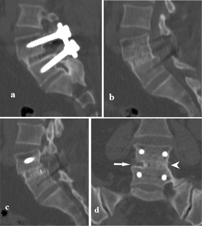
Figure 5.

Failure of osseous fusion at L4/5 interbody space, grade (D): decompression surgery at L4-5 level and internal fixation. Sagittal images (a, b): lack of bone bridges all through the interbody space in addition to erosive changes of the vertebral end plates (short arrow) and anterior displacement of L4. Axial images (c, d): malpositioned right screw, severely medially penetrating the pedicle and intruding into the spinal canal.
We further analysed the MDCT findings at the levels of failed osseous fusion, grade (D), at the interbody levels in Table 6. The primary finding in these levels is lack of bone bridges between the vertebrae (Figures 5 and 6). In two patients, bone bridges within and around the disc cage were detected at their interbody levels but in fact representing mature pseudoarthrosis (Figure 7). In other two patients, pseudoarthrosis at the posterolateral spaces was detected in the form of sclerosed bone margins and linear defects in between the bone bridges (Figure 8).
Table 6.
Analysis of MDCT signs in grade D, failure of osseous fusion
| MDCT signs of failure of fusion | Number of levels | |
|---|---|---|
| New bone bridges at the interbody spaces | Lack of bone bridges | 9 |
| Pseudoarthrosis | 2 | |
| New bone bridges at the posterolateral spaces | Lack of bone bridges | 12 |
| Pseudoarthrosis | 2 | |
| Instruments | Screws loosening | 6 |
| Screws malposition | 4 | |
| Cage subsidence or migration | 4 | |
| Graft resorption | 3 | |
| Broken rods | 2 | |
| Vertebral end plates | Erosive changes | 9 |
| Others | Adjacent levels spondylodegeneretive changes | 11 |
| Malalignment | 6 | |
| Vacuum phenomenon | 4 |
Figure 6.

Failure of osseous fusion at L4/5 interbody space, grade (D) and chronic spondylodiscitis: decompression surgery at L4-5 level and internal fixation. Sagittal (a) and coronal (b) images: lack of bone bridges all through the interbody space in addition to mixed erosive and sclerotic changes of the vertebral bodies representing sequel of chronic spondylodiscitis. Axial CT images (c, d, e): evident erosions of the vertebral end plates mixed with sclerosis, osteolysis around the pedicular screw (arrow) with subsequent loosening and penetration of the lateral cortex.
Figure 7.

Failure of osseous fusion at L5/S1 interbody space with pseudoarthrosis, grade (D): decompression surgery at L5-S1 level, disc cage placement and internal fixation using pedicular screws and rods. Sagittal (a, b, c) and coronal (d, e) images: lack of bone bridges all through the intervertebral body space, apart from bone within the disc cage, representing mature pseudoarthrosis (arrow). Anterior displacement of L5, erosive and sclerotic changes of the opposing end plates, vacuum phenomenon and migration of cage material (double arrow).
Figure 8.

Fusion at L3/4 posterobilateral spaces: solid bone mass completely covering the right posterolateral space (long arrow), while on the left incomplete bone bridges with linear defects and sclerosed bone margins are noted (short arrow) representing pseudoarthrosis.
Additional findings included instruments loosening, malpositioning and breakage, spondylodegenerative changes, erosive changes of vertebral end plates, malalignment and vacuum phenomenon.
In the patients with grade (A) successful fusion, we reported spondylodegenerative changes in seven patients and ligamental calcification in two patients. No vertebral end plates erosive changes were detected in grades (A) and (B) patients, while two patients with grade (C) showed such changes.
Other peri-, intra- or extraspinal complications
Active infection (abscess) was detected in one early post-operative MDCT scan and chronic spondylodiscitis in one late post-operative scan. In both, the patients’ histopathological and other investigations data confirmed active infection. Post-operative haemothorax was detected in four premier post-operative MDCT scan.
Discussion
In imaging of post-operative spine patients, MDCT with its excellent anatomical details is considered the modality of choice in evaluation of instruments position and integrity and assessment of the status of osseous fusion. The main limitation of CT imaging in post-operative spine patients has always been beam hardening artefacts related to orthopedic prosthesis. The modern generations of MDCT scanners and the recent software programs helped to minimize these undesirable artefacts.2
In the dilemma of post-operative imaging of the spine, it is important to know what we are looking for. It is essential for the radiologist to be aware of possible post-operative spine complications which differ according to the timing at which images are obtained post-operatively.
In our study, we interpreted MDCT findings in three groups of patients categorized according to their scan date following spine surgery. Early post-operative complications include instruments related complications, collections secondary to CSF leakage and infection.3 In the clinical setting of suspecting nerve root impingement due to malplacement of screw position, CT imaging is of value, while MRI would be more valuable for detection of early infection and small CSF leakage. Late post-operative imaging assessment expands to include complications related to osseous fusion status.
Instrument related complications
In spine surgeries, instruments are used to ensure immobilization and stabilization of a spine segment. The earlier usage of autogenous bone grafts without instrumentation were largely unsuccessful; hence variable instruments as pedicles screws, interbody fusion devices and bone grafts are frequently used to restore disc spaces and vertebral alignment, to stabilize the spine and to enhance osseous fusion.6 Previous studies revealed the reliability of CT images to detect malpositioning of screws.7
The reported incidence of screws malpositioning in reviewed literature, considering it a technically demanding procedure, is variable. In our study, malpositioned screws were detected in 99 out of 275 screws (36%). Lotfinia et al4 reported 35.22% faulty screws placements and in earlier studies Castro et al8 and Laine et al reported cortical penetration in 40 and 21% of the screws in their studies, respectively. In more recent research studies, lower incidences (<20%) were reported.9,10 The high incidence of screws malpositioning and the substantial high numbers of severe grades of pedicles penetration in our study are explained by relatively high number of failed osseous fusion. The altered biomechanics secondary to instability influence the position of screws.
The highest number of screws malpositioning was in the form of penetration of the vertebral pedicles, being higher in the medial direction. This is of particular importance as previously reported by Lonstein. et al. In their series, most of the patients who suffered nerve root irritation were attributed to medial pedicle penetration.11 In many studies, minor grade of pedicles perforation (within 2 mm of the cortex) is not considered as malpositioned screws. Authors attribute to lack of symptomatology in these patients and consider such range as acceptable.4,10
Assessment of osseous fusion
The superiority of CT images in following the progress of osseous fusion is documented and implemented in various research studies.5,6,12–17 It takes not less than 3 months to visualize bone bridges and it is optimum to judge osseous fusion at 6 to 9 months’ post-operatively.6 New bone formation usually starts to develop lateral to the placed device and progress to completely cover the interbody space. There should be no linear defects through the bridging bone.
In our study, a considerable number of levels, constituting 45.8 and 22.8%, showed signs of failed osseous fusion, categorized as grade (D). On analysis of MDCT findings at failed osseous fusion at the interbody spaces, failure to detect new bone bridges was not the sole finding. Additional findings included instruments loosening, malpositioning and breakage followed by spondylodegenerative changes and vertebral end plates erosive changes in order of frequency.
The spine instability secondary to failure of osseous fusion to develop and mature influence the position and integrity of placed instruments. Lucency around the applied instruments (loosening) denotes osteolysis secondary to inevitable continuous motion. Subsidence and migration of disc cage material are also a form of instruments malpositioning. Subsidence is sinking of disc cage into the adjacent vertebrae. The applied graft may even get resorbed instead of being incorporated into adjacent bones. Such spectrum of instruments malpositioning was detected in our study, mostly in the form of screws loosening. Loss of instruments integrity was detected in two patients in the form of broken rods.
Accelerated spondylodegenerative changes at the adjacent levels represent sequel of lack of stability; however, it is a non-specific finding being detected in other patients as well, including complete osseous fusion, due to altered biomechanics. On the other hand, end plates erosive changes were frequently detected in grade (D) followed by grade (C) and not seen in grades (A) and (B). This amplifies its significance as a marker of failed fusion.
Kim et al18 reported traction osteophytes at 52.6% of the levels of failed fusion. We did not report a similar finding in our study. This might be attributed to the smaller number of assessed levels in our study.
Although fusion of spinal segments is the target of surgeries, it may result in undesirable sequel. This includes accelerated degenerative changes at the adjacent segments, ligamental calcification and fractures.19 We reported spondylodegenerative changes and ligamental calcification in patients who were categorized as grade (A).
Finally, optimized MDCT protocols in post-operative spine imaging produce high-quality images, allowing adequate evaluation of instruments position and integrity and fair assessment of osseous fusion. Our results include a spectrum of findings in early and late post-operative cases with variable osseous fusion status. Although the included number of patients is limited, yet we observed a good variety of cases and MDCT findings. This encourages us to propose a helpful algorithm (Figure 9) to simplify interpreting MDCT images in post-operative spine and to be a step for future larger studies in a prospective design aiming at producing standardized guidelines.
Figure 9.

Algorithm for possible complications on MDCT images of post-operative spine.
Conclusion
Modern MDCT scanners, implementing protocols to combat beam hardening artefacts, provide high quality images and are strongly recommended in evaluation of instruments position and integrity and assessment of the status of osseous fusion. Post-operative imaging of the spine is a dilemma in which it is essential to be aware for what you are looking for, in relevance to the date of surgery.
Acknowledgments
The authors would like to thank Dr khaled Abd El Baky Ahmed El Hannan for his assistance.
Contributor Information
Rania Zeitoun, Email: rania.zeitoun@kasralainy.edu.eg.
Manar Hussein, Email: manarhussein@yahoo.com.
References
- 1.Douglas-Akinwande AC, Buckwalter KA, Rydberg J, Rankin JL, Choplin RH. Multichannel CT: evaluating the spine in postoperative patients with orthopedic hardware. Radiographics 2006; 26 Suppl 1: S97–S110. DOI: https://doi.org/10.1148/rg.26si065512 [DOI] [PubMed] [Google Scholar]
- 2.Thakkar RS, Malloy JP, Thakkar SC, Carrino JA, Khanna AJ. Imaging the postoperative spine. Radiol Clin North Am 2012; 50: 731–47. DOI: https://doi.org/10.1016/j.rcl.2012.04.006 [DOI] [PubMed] [Google Scholar]
- 3.Hayashi D, Roemer FW, Mian A, Gharaibeh M, Müller B, Guermazi A. Imaging features of postoperative complications after spinal surgery and instrumentation. AJR Am J Roentgenol 2012; 199: W123–W129. DOI: https://doi.org/10.2214/AJR.11.6497 [DOI] [PubMed] [Google Scholar]
- 4.Lotfinia I, Sayahmelli S, Gavami M. Postoperative computed tomography assessment of pedicle screw placement accuracy. Turk Neurosurg 2010; 20: 500–7. DOI: https://doi.org/10.5137/1019-5149.JTN.3215-10.1 [DOI] [PubMed] [Google Scholar]
- 5.Carter JD, Swearingen AB, Chaput CD, Rahm MD. Clinical and radiographic assessment of transforaminal lumbar interbody fusion using HEALOS collagen-hydroxyapatite sponge with autologous bone marrow aspirate. Spine J 2009; 9: 434–8. DOI: https://doi.org/10.1016/j.spinee.2008.11.004 [DOI] [PubMed] [Google Scholar]
- 6.Williams AL, Gornet MF, Burkus JK. CT evaluation of lumbar interbody fusion: current concepts. AJNR Am J Neuroradiol 2005; 26: 2057–66. [PMC free article] [PubMed] [Google Scholar]
- 7.Kosmopoulos V, Theumann N, Binaghi S, Schizas C. Observer reliability in evaluating pedicle screw placement using computed tomography. Int Orthop 2007; 31: 531–6. [DOI] [PMC free article] [PubMed] [Google Scholar]
- 8.Castro WH, Halm H, Jerosch J, Malms J, Steinbeck J, Blasius S. Accuracy of pedicle screw placement in lumbar vertebrae. Spine 1996; 21: 1320–4. DOI: https://doi.org/10.1097/00007632-199606010-00008 [DOI] [PubMed] [Google Scholar]
- 9.Amiot LP, Lang K, Putzier M, Zippel H, Labelle H. Comparative results between conventional and computer-assisted pedicle screw installation in the thoracic, lumbar, and sacral spine. Spine 2000; 25: 606–14. DOI: https://doi.org/10.1097/00007632-200003010-00012 [DOI] [PubMed] [Google Scholar]
- 10.Weise L, Suess O, Picht T, Kombos T. Transpedicular screw fixation in the thoracic and lumbar spine with a novel cannulated polyaxial screw system. Med Devices 2008; 1: 33–9. [DOI] [PMC free article] [PubMed] [Google Scholar]
- 11.Lonstein JE, Denis F, Perra JH, Pinto MR, Smith MD, Winter RB. Complications associated with pedicle screws. J Bone Joint Surg Am 1999; 81: 1519–28. DOI: https://doi.org/10.2106/00004623-199911000-00003 [DOI] [PubMed] [Google Scholar]
- 12.Nakashima H, Yukawa Y, Ito K, Horie Y, Machino M, Kanbara S, et al. Extension CT scan: its suitability for assessing fusion after posterior lumbar interbody fusion. Eur Spine J 2011; 20: 1496–502. DOI: https://doi.org/10.1007/s00586-011-1739-0 [DOI] [PMC free article] [PubMed] [Google Scholar]
- 13.Cook SD, Patron LP, Christakis PM, Bailey KJ, Banta C, Glazer PA. Comparison of methods for determining the presence and extent of anterior lumbar interbody fusion. Spine 2004; 29: 1118–23. DOI: https://doi.org/10.1097/00007632-200405150-00013 [DOI] [PubMed] [Google Scholar]
- 14.Togawa D, Bauer TW, Brantigan JW, Lowery GL. Bone graft incorporation in radiographically successful human intervertebral body fusion cages. Spine 2001; 26: 2744–50. DOI: https://doi.org/10.1097/00007632-200112150-00025 [DOI] [PubMed] [Google Scholar]
- 15.Tan GH, Goss BG, Thorpe PJ, Williams RP. CT-based classification of long spinal allograft fusion. Eur Spine J 2007; 16: 1875–81. DOI: https://doi.org/10.1007/s00586-007-0376-0 [DOI] [PMC free article] [PubMed] [Google Scholar]
- 16.Burkus JK, Dorchak JD, Sanders DL. Radiographic assessment of interbody fusion using recombinant human bone morphogenetic protein type 2. Spine 2003; 28: 372–7. DOI: https://doi.org/10.1097/01.BRS.0000048469.45035.B9 [DOI] [PubMed] [Google Scholar]
- 17.Burkus JK, Transfeldt EE, Kitchel SH, Watkins RG, Balderston RA. Clinical and radiographic outcomes of anterior lumbar interbody fusion using recombinant human bone morphogenetic protein-2. Spine 2002; 27: 2396–408. DOI: https://doi.org/10.1097/00007632-200211010-00015 [DOI] [PubMed] [Google Scholar]
- 18.Kim KH, Park JY, Chin DK. Fusion criteria for posterior lumbar interbody fusion with intervertebral cages : the significance of traction spur. J Korean Neurosurg Soc 2009; 46: 328 DOI: https://doi.org/10.3340/jkns.2009.46.4.328 [DOI] [PMC free article] [PubMed] [Google Scholar]
- 19.Young PM, Berquist TH, Bancroft LW, Peterson JJ. Complications of spinal instrumentation. Radiographics 2007; 27: 775–89. DOI: https://doi.org/10.1148/rg.273065055 [DOI] [PubMed] [Google Scholar]
- 20.Laine T, Mäkitalo K, Schlenzka D, Tallroth K, Poussa M, Alho A. Accuracy of pedicle screw insertion: a prospective CT study in 30 low back patients. Eur Spine J 1997; 6: 402–5. DOI: https://doi.org/10.1007/BF01834068 [DOI] [PMC free article] [PubMed] [Google Scholar]