 An organoionic crystal of tetrabutyl-n-phosphonium tetraphenylborate thermally recovers its shape through superelasticity, similar to shape-memory alloys.
Abstract
Shape-memory materials, i.e., polymers (SMPs: shape-memory polymers) and alloys (SMAs: shape-memory alloys), have been developed in very different ways since they are historically far apart in material type as well as physical property. In the deformation process, SMPs require only a slight stress due to the properties of organic polymer solids, and they reveal a smaller recovery force during the thermoplastic process whereas SMAs require a relatively large stress due to metallic properties, and they thermally tighten to generate a larger recovery force via destabilization of the stress-induced phase. An investigation into the unexplored area of the material adjoining both ends of SMPs and SMAs would lead toward a better understanding of shape-memory materials and extend future applications and material types. Here, we report the discovery of a shape-memory effect in an organic crystal bearing a combination of crystal transformability like in SMAs with organic components like SMPs.
Introduction
Shape-memory materials are fascinating materials that regain their original shapes from mechanically deformed states and are categorized into polymers and metal alloys. The two material types are completely different, not only in type of material but also in the nature of their shape-recovery. Shape-memory polymers1 (SMPs) are rather flexible and work via thermal relaxation of the polymer to show their hidden tensility via the positional reversion of embedded linkup or stable bundling points, whereas shape-memory alloys2 (SMAs) are stiff and transform to gain enough recovery force to overpower stiffness via thermal phase destabilization of the stress-induced domains. Thus, SMP recovery during the thermoplastic process is feeble whereas SMA recovery is powerful with an increased tension with a rise in temperature.
After the term “shape memory” appeared during the development of Ni–Ti as an engineering alloy in 1960s,3 SMAs have been under focus because of their new properties and anticipated applications. The shape-memory effect is considered to be a phenomenon strongly related to superelasticity. The earliest reports on shape memory and superelasticity were made for Au–Cd in 1951 (ref. 4) and 1932.5 Despite the advantages of strength and/or durability in applying shear via the operation of tension or compression, metal alloys require a certain amount of energy input to cause deformation. Thus, a certain bias force is needed in the cyclic actuating motion, which causes problems in micro-device applications such as micro springs, micro valves, and microelectromechanical systems (MEMS). Furthermore, materials free of toxic elements are required, especially for medical uses from a biocompatible perspective. The chemical synthesis of SMA-like materials would bring important contributions to the evolution of materials science since the current SMA materials are limited to metal alloys and ceramics.6
While the mechanism of the shape-memory effect of SMAs is not fully understood, Otsuka and Shimizu proposed the empirical hypothesis for SMAs7 that the shape-memory effect and superelasticity are fundamentally coexisting phenomena; one phenomenon appears by giving the appropriate temperature if the other phenomenon appears. In particular, the thermoelastic martensitic transformation, which generates mobile interfaces during the growth of daughter domains via temperature change, is commonly thought to be important for thermomechanical shape-recovery motion, which is the so-called shape-memory effect in SMAs.
On the other hand, the term “shape-memory” in polymer science is rather new, appearing in the middle of the 1980s,8 where SMP shape recovery occurs during thermal softening around the glass transition temperature to release the restraint in shape recovery motion. The shape memory effect involved in SMAs was not known for any organic materials including SMPs although organic materials do have extendibility in various kinds of polymers in developing functional material chemistry. Thus, we thought that an investigation into the unexplored area of the material adjoining both ends of SMPs and SMAs would lead toward a better understanding of shape-memory materials and extend future applications and material types.
Considering the current situation of SMAs and SMPs, shape-memory materials having both powerful recovery and easy deformation have not yet been identified and there is no such applicable theory for it. While polymers and metals obviously have promising potentials for elastic materials, molecular crystals consisting of organic compounds have not been of much interest because organic crystals seem to be poorly suited to handle mechanical stress.
We have discovered that organic crystals potentially show superelasticity (organosuperelasticity),9,10 which allows the recovery of their shapes from mechanical deformation with a martensitic transformation while some organic and organoionic crystals are known to exhibit a shear-induced martensitic transformation without spontaneous shape-recovery properties.11–14 However, we could not find the shape-memory effect in the organosuperelastic crystals of terephthalamide9 or 3,5-difluorobenzoic acid,10 probably due to the poor thermal connection of their mechanical phase. SMAs are known to have a specific thermal phase connection between their superelastic region and twinning region.
Consequently, the requirements for organic material design towards an SMA-like behavior would naturally be concerned with the capability of thermal transition under the suppression of a component's diffusion for generating a martensitic transformation with the thermally interchangeable superelasticity connected to the lower twinning region without spontaneous restoration characteristics. Furthermore, metal alloys have many compositions and ordered alloys are known to prefer martensitic (non-diffusive) transformation to complicated plastic deformation.
Considering the empirical material and thermal characteristics of SMAs mentioned above, we focused on the relatives of plastic crystals15 but without transiting into the mesophase despite the fact that plastic deformation derived from the events of easy dislocation and a slide could occur due to weak interactions among organic components. We investigated organoionic single crystals consisting of binary molecular components with a spherical shape as similar as possible to the rigid sphere atomic components in metal alloys. Herein, we report the first SMA-like shape-memory effect of organic molecular crystals. The material exhibits powerful shape recovery along with easy deformability.
Results and discussion
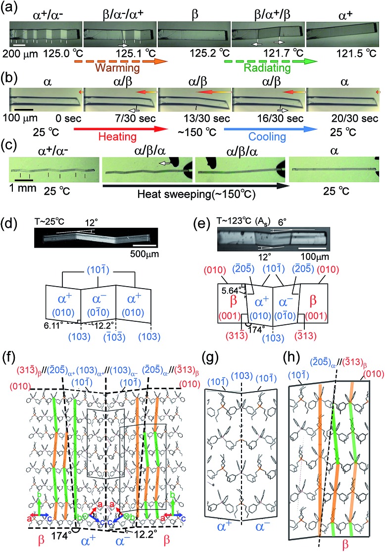
The compound is tetrabutyl-n-phosphonium tetraphenylborate ((PnBu4)+(BPh4)– (1)). Its single-crystals were prepared via recrystallization from an acetone solution of crude 1, which was first obtained as a precipitate from a mixed aqueous solution of PBu4Cl and NaBPh4. While the crystal 1 is soft with a 0.88 GPa Young’s modulus at room temperature, similar to high-density polyethylene, 1 exhibits a martensitic transformation rather than plastic deformation (Fig. 1). Through application of shear force at room temperature, a colorless rod-shaped crystal (α phase) underwent a stress-induced martensitic transformation in growing a twin (α+/α– state) with mobile planar phase boundaries across the crystal rod keeping an invariant bending angle of 12°. Sequential displacement of the shear position on the crystal rod can form zigzag crystals through the use of tweezers under a microscope. Upon homogeneous warming, the deformed crystal regained its straight shape, showing the thermal shape recovery of 1 (Fig. 1a). In contrast, applying heat to the straight rod-shaped crystal with a longitudinally thermal gradient bent the crystal by generating a high-temperature phase (β) from the original phase (α). This was done in a quick shifting bending position by regulating the applied heat with a definite bending angle of 6° at the boundary (Fig. 1b). The practical shape-memory effect of 1 was clearly confirmed via heat sweeping of the deformed crystal specimen with the partial generation of the β phase through the α/β/α transient state (Fig. 1c).
Fig. 1. Thermal shaping recovered the deformed zigzag α+/α– prepared at room temperature to the “remembered” straight rod β: around 125.0 °C by warming (a); thermal actuation for cyclic α ⇄ β/α transformation via heat fluctuation with an iron at 150 °C (b); and shape recovery via a heat-sweep over the deformed zigzag pattern of α+/α– (c) (Movie S1†). Crystal morphology (d–h): photographs taken with a polarized microscope with accompanying crystal face indexes caused by shear at room temperature for the α+/α– twin (d) and around 123 °C for the α+/α–/β multiphase (e); and the molecular correspondence at the interface estimated using X-ray results (β/α+/α–/β (f), and magnified for α+/α– (g) and α–/β (h)). Color auxiliary lines in (f) and (h) indicate the molecular alignments.
Single-crystal X-ray diffraction analysis16 gave the crystal connections under the shear-induced bending state. By warming the crystal 1, the crystal system changed from triclinic P1 in the α phase (394 K, V/Z: 960.7 Å3) into monoclinic P21/n in the β phase (403 K, V/Z: 968.5 Å3) with a 0.8% expansion in volume (Table S1†). Crystal face indexing showed the interfaces for shear-induced twinning with α+/α– ((103)α+//(103)α– and (103)α–//(103)α+) and for the heat-induced crystal of α±/β ((205)α+//(313)β and (205)α–//(313)β), respectively (Fig. 1d and e).
Since the neighbouring crystal cells fit exactly at the mirror interface in α+/α–, there is no lattice strain at the interface although a conformational strain can exist in the component molecules on the interface. In contrast, a certain lattice strain did exist at the α/β interface with the rate of facing crystal surfaces of 0.98 for S(205)α+/S(313)β.
Thus, the α and β crystal faces should respectively feel the forces of face extension and contraction, which can generate a certain shear contributing to a reverse transformation. The crossing plane angles related to the unit cells from the X-ray data are estimated at 12.2° and 5.3° for the α+/α– and α±/β (= α+/β or α–/β) connections, respectively, which is in agreement with the crystal bending angles of 12.0° and 6.0° observed under a microscope. This demonstrated how to preserve one-to-one molecular correspondence during transformation to satisfy the martensitic manner (refer to Fig. 1d and e). The α+/α– connection takes a rotary reflection plane regarded as a Type II twin,17 which requires the rotation of the molecules when the boundary moves during the crystal transformation. The α±/β interface has a similar correlation in the α+/α– interface. The density of the molecules at the interface should be unchanged in α+/α– and its waviness changed along the α±/β boundary plane. In the appearance of the α±/β interface, the method of deviation of the molecular density (orange and green lines in Fig. 1f and h) determines the interface of either α+/β or α–/β. Since molecular components have certain complexities in figures unlike the atomic components in SMAs, the molecular correspondence at the interface can be regulated via a change of orientation and conformation as well as their relative position. A minimal molecular rotation with a harmonic conformational change can achieve molecular correspondence in the interface without a break in the crystal.
Thermal transition for 1 from the low temperature phase (α) to the high temperature phase (β) was confirmed via DSC measurements (Table 1 and Fig. S3†). The transition temperatures and thermodynamic parameters were: Tα–β = 122.94 °C; ΔH (ΔS) = 3.01 kJ mol–1 (7.60 JK–1 mol–1) for the transition from the α phase to the β phase; Tm = 230.05 °C; ΔH (ΔS) = 41.0 kJ mol–1 (81.4 JK–1 mol–1) upon melting. Because of the sufficiently large ΔS (>20.9 JK–1 mol–1 (ref. 18)) upon melting, the β phase should not be considered as a plastic mesophase but instead as an ordinal crystal phase. The temperature hysteresis can be defined using four pertinent transition temperatures (Mf (Te for cooling), Ms (T0 for cooling), As (T0 for heating), and Af (Te for heating) were 118.56, 120.46, 123.00, and 124.97 °C, respectively, with respect to the scientific notation for SMAs) with an extremely small separation of 2.5 K between As and Ms for 1. Since interfacial inconsistency increases the separation in a temperature hysteresis, 1 should have good interfacial consistency, which is preferable to the non-diffusional crystal-to-crystal transformation accompanying the crystal phase transition. The α–β thermal structural transition of 1 was confirmed using PXRD measurements (Fig. S4†).
Table 1. Thermodynamic parameters obtained using DSC measurements for 1.
| Phase transition (α to β) |
Melting (fusion of β crystal) |
Index temperature |
||||||
| T α–β/°C | ΔH/kJ mol–1 | ΔS/JK–1 mol–1 | T m/°C | ΔH/kJ mol–1 | ΔS/JK–1 mol–1 | A s (Af)/°C | M s (Mf)/°C | A s–Ms/°C |
| 122.94 | 3.01 | 7.60 | 230.05 | 41.0 | 81.4 | 123.00 (124.97) | 120.46 (118.56) | 2.54 |
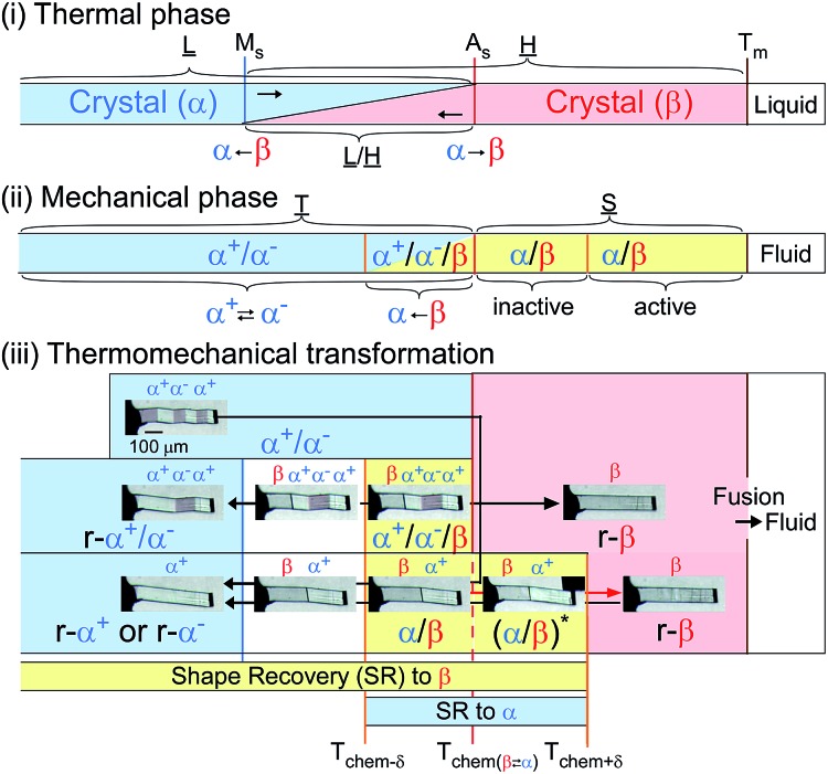
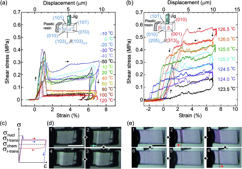
From the thermal perspective of the crystal phase of 1, the crystal phase should be α below Ms (L) and β over As (H) (Fig. 2i). Either phase is allowed between Ms and As (L/H) when the dependence on temperature is going up from α or down from β. We recorded the cyclic strain curves caused by shear on (101)α and (010)β at various temperatures between –50 °C and 130 °C. The conditions of the cyclic shear test on crystal 1 are summarized in Table S2.† The kinetic properties can be divided into the martensitic twinning (T) and superelastic (S) regions. In the shear-induced transformation of 1 under our experimental conditions, T spreads from at least –50 °C to As (123 °C) in L. The superelastic region (S) is located from As up to at least 129 °C in H. In T, the crystal transformed following α+ → α– with a constant amplitude of shear and left a residual strain (Fig. 3a). In contrast, the crystal was spontaneously restored above the As temperature at the beginning of S (Fig. 3b). The shear for the reverse transformation showed cyclic shear–strain curves without residual strain. With a typical plateau, the cyclic curves demonstrated superelasticity (organosuperelasticity9,10) during the progress of the transformation. The superelastic transformation of 1 was reproduced in 100 cycles of measurements at 124.5 °C (Fig. S10†).
Fig. 2. Phase diagram for 1: thermal transition (upper), kinetic phase diagram for force-induced mechanical phase (middle), and shape-recovery diagram for thermomechanical transformation (bottom) (Ms, 120.46 °C; As, 123.00 °C; Tm, 230.05 °C. SR, r-α or r-β mean shape recovery and crystal phase restored into the original shape. *Shear is needed to conserve the deformation).
Fig. 3. Shear–strain curves for single crystal 1 at various temperatures: martensitic transformation of twinning α (a) and superelastic β (b) caused by pushing the top surface of the crystal specimen fixed on a hot and cold stage. The experimental conditions are summarized in Table S2,† and all stress–strain curves are shown in Fig. S8.† In the current shear direction, based on the crystal data, the maximum strain (εmax) is expected for α+/α– at 0.217 and for β/α at 0.107 according to the combination of cells. The schematic curve in the lower left shows typical traces for twinning (blue) and superelasticity (red) with the designations of shear used in this paper (c). Photographs with a polarized microscope at –10 °C (d) and 126.5 °C (e) (Movie S2†).
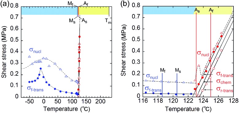
From the shear–strain curves in Fig. 3a and b, the notation in the shear tests pointed to the typical curve for σ#(mother → daughter) (#: nucleation, forward-transformation, reverse-transformation, and chemical) (Fig. 3c). The critical shear for the transformation, σf-trans, exhibited a slight decrease with a rather constant amplitude with an elevation of the temperature from –50 °C up to As, at which point σf-trans(α+ → α–) was replaced with σf-trans(β → α) along the thermal change of the mother crystal phase from α to β (Fig. 4 & S9†).
Fig. 4. Temperature dependence of the index shears (σnucl (triangle), σf-trans (solid circle), and σr-trans (circle) (σchem is depicted as the mean line of σf-trans and σr-trans)): general drawing (a) and extended graph around As (b) (blue and red plots indicate the stressed crystal phase for α and β, respectively. The chart upper limb has a color band for indicating the phase according to the phase diagram in Fig. 2(ii).) (Mf: 118.56 °C; Ms: 120.46 °C; As: 123.00 °C; Af: 124.97 °C).
The amplitude of σf-trans showed a sharp peak of 0.25 MPa around –10 °C, which immediately decreased to 0.11 MPa at 20 °C, and then decreased slightly, approaching 0.02 MPa below As. Across As, σf-trans increased linearly in temperature with a gradient of 0.135 MPa °C–1. The gradient is known to be related to the enthalpy change and rate of strain in the transformation (4.11 MPa °C–1 for the Ti–Ni alloy)19 (the estimated transformation enthalpy is –3.26 kJ mol–1 for 1 using the Clausius–Clapeyron equation20). The amplitude of σnucl followed the temperature course of σf-trans(α+ → α–) in a moderate manner and eventually became undetectable after showing a peak after immediately passing As. After reaching the S region, superelasticity takes place. The vertical (shear stress) width in the shear–strain hysteresis was regarded as being constant at 0.123 MPa to depict the parallel lines for σf-trans(β → α) and σr-trans(β ← α). The linear increase of σf-trans(β → α) and σr-trans(β ← α) was launched from an almost negligible shear. This means that the indexes for a superelastic transformation change along with the temperature (refer to Table S3 & Fig. S11†). For the definition of S, the chemical shear (σchem(β ⇄ α)) should be considered, which is located between σf-trans(β → α) and σr-trans(β ← α). The mean line can be the chemical shear (σchem) because the width of the two lines seems to be sufficiently narrow although the position of σchem should be shifted due to the relationship between the difference in the thermodynamic energy of the crystal phase and, in addition, the loss of energy depending on the way of deformation.
The σchem(β ⇄ α) just intercepts As at which Tchem(β ⇄ α) can be defined. This is reasonable since the phase change should cause the chemical evocation of the reverse transformation. As is the temperature in the crossing of the Gibbs free energies of the α and β phases while σf-trans and σr-trans are expected to intercept at the Ms and As temperatures,21,22 respectively, if the common kinetics correlation is considered, which was proposed for thermomechanical pseudoelasticity in SMAs.23 From a general view, the observed thermomechanical diagram for 1 is similar to the thermoelastic martensitic transformation for SMAs proposed by Otsuka and Shimizu in 1986.24
A more detailed definition is required for the thermomechanical transformation of the shape recovery of 1. In the temperature range between Tf-trans(β → α) and Tr-trans(β ← α), which includes a temperature region even lower than As, an applied force can induce β → α transformation to lead to an α/β crystal state without a spontaneously reversing transformation.
Considering the allowance of α+ → α– twinning caused by shear, the static deformed state should be categorized into three temperature parts: α+/α– below Tchem–δ, α+/α–/β between Tchem–δ and Tchem, and β/α between Tchem and Tchem+δ (refer to Fig. 2(iii)). Thus, the shape-memory region (mechanically deformed state) can take α+/α– below As (Tchem). The α+/α–/β deformation can be prepared between Tchem–δ and Tchem and superelastically regain the β solid shape if crossing over Tchem+δ with elevating temperature. The superelastic recovery of the deformed crystal needs a δ rise in temperature against the thermal transition temperature of As (Tchem). The shape-recovery velocity (vr-trans) in the spontaneously superelastic reverse transformation increases in proportion to the square of the temperature as the strength of the induced shear increases in relation to vr-trans ∝ σr-trans2 (∵ σr-trans ∝ (T–Tchem+δ)), which is suggestive of the conversion of the potential energy to kinetic energy (Fig. S5†). In the heat-induced reversible transformation, the crystal of 1 thermally transforms across the transition temperatures of Ms (β → α) and As (α → β) in the manner of an isothermal martensitic transformation. Due to the ease in the interface shuttle in 1, a mere thermal transition can recover the shape upon generating a slight shear of 0.03 MPa at Ms and less than 0.01 MPa at As (Fig. S9†).
The temperature part between Tchem–δ and Tchem+δ, which depends on the shear–strain hysteresis, takes the two-way shape-memory region25 since the mechanical deformation in this temperature range is capable of recovering the α → β and β → α thermal transformations for heating and cooling, respectively.
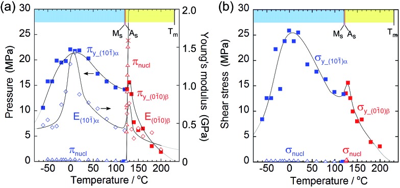
In order to investigate the thermal replacement of the martensitic transformation with crystal breaking under stress, a unidirectional compression test was performed on the (101)α and (010)β crystal faces, the same direction as in the shear tests (Fig. 5). The plastic deformation derived from the events of easy dislocation and a slide could occur despite organic molecular solids with weak intermolecular interaction. For example, simple ionic crystals such as sodium chloride are known to be typical solids that undergo plastic deformation.26
Fig. 5. Comparison of yield stress (#y) and nucleation stress (#nucl) with respect to pressure (π) on the surface (a) and shear (σ) (b). Young's modulus (E) is added in the left figure to understand the similarity of E to πy.
As the temperature increased, Young's modulus (E), which concerns the elastic hardness of a solid, changed from 0.5 GPa at –30 °C to a peak of 1.43 GPa at 10 °C, decreased almost linearly to the Ms point with 0.4 MPa, jumped around As to show a sudden peak at 130 °C with 0.9 GPa, and finally decreased quickly and approached zero at the melting temperature. The yield pressure πy started at 10 MPa and ended at 1 MPa close to the melting point at 230 °C through the highest peak around 10 °C and jumped around 130 °C in the same manner as the Young modulus but in a rather moderate fashion. At the narrow region over As just after the thermal phase changed from the α to the β crystal phase, the Young modulus and the yield pressure suddenly jumped, resulting in getting a tentative hardness of the β phase crystal with an increase in the tolerance toward crystal compression against stress.
From the viewpoint of crystal breaks caused by stress, some deformation can occur if a solid yields plastically before the martensitic transformation begins. The yielding process should match the compression pressure πy at the contact area of the jig (Fig. 3a and b, and Fig. 5a). The crossing point of πy and the nucleation pressure (πnucl) is around 125 °C. Consequently, the crystal breaking of 1 is triggered by local compression on the jig, which determines the border temperature in H. An effective measurement configuration will practically save the wider temperature region of S with a larger jig contact area.
Although the crossing of nucleation stress and yield stress in terms of pressure and shear was not observed in L, the crystal seemed to break due to dislocation generation because it broke into a mosaic form at around –60 °C whereas it broke in a cleavage manner at around 130 °C.
The thermomechanical characteristics of 1 measured on microcrystals showed an easy deformation, less than with SMPs (polyurethane27), with a thermal increase in the directional recovery shear (σr-trans) up to 10 MPa with 5 × 10² times more force back against the twinning shear (σf-trans) of 0.02 MPa below As, which is beyond SMAs (Ti–Ni alloy19) with 2.6 times that in width, as shown in Fig. 6.
Fig. 6. Comparison of the yield stress (or critical shear) of 1 (Ms: 120.46 °C; As: 123.00 °C; Tm: 230.05 °C) with a representative SMP (polyurethane;27Tg: 32 °C) and SMA (Ti–Ni alloy;19Ms: 75 °C, As: 89 °C).
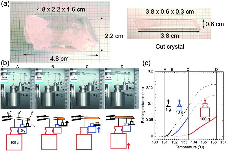
A single crystal of 1 with a 1 cm2 cross-sectional area is expected to lift a 100 kg weight horizontally with 10 MPa recovery shear generation around 200 °C if σf-trans linearly increases in temperature with a gradient of 0.135 MPa °C–1 from the As temperature. In order to visually observe the lifting work, we prepared a large single crystal and cleaved it into a 3.8 cm long specimen of 0.6 g in self-weight with a 0.18 cm2 (0.6 × 0.3 cm) cross-sectional area, which had a 1.8 kg lift capability with a 1 MPa recovery shear around 130 °C. Considering the current experimental configuration, we hung SUS weights of 1, 10, and 100 g (more than 102 times heavier than the specimen's own weight) with a SUS filament on the single-crystal specimen after the specimen was manually deformed below As. After the experimental system was warmed in an oven, the specimen regained its default straight shape via sequential lifting as the recovery shear increased during the rise in temperature, demonstrating the practical and feasible work capability of the shape-memory effect of 1, (Fig. 7) although the lifting started at 131.0 (1 g), 131.8 (10 g), and 133.4 (100 g) °C, which are higher by 5.9 (131.0–125.1)–8.2 (133.4–125.2) °C than the expected starting temperatures from the microcrystal experiments depicted in Fig. 1a, probably due to the non-ideal strain in a large crystal specimen hanging heavy weights. This demonstrates the desired characteristics of shape-memory materials for miniaturization and conversion of heat into a practical work output within a narrow temperature cycle. It should be noted that 1 exhibits a high Af point of 124.97 °C, which is higher than 110 °C known as the highest limit for binary Ni–Ti alloys without any additive.
Fig. 7. Photographs of a large single-crystal and a cut crystal for the lifting experiment (a). Snapshots extracted from Movie S3† during the lifting work of 1 hung by 1, 10, 100 g SUS weights in an oven with a schematic diagram for the explanation (b) and a sequential lifting course for each weight with temperature rise (c).
Conclusions
In conclusion, we demonstrated a transcendent shape-memory effect in an organic crystal, which can thermally generate a large recovery force in an SMA-like thermal manner with easier deformability than that of SMPs. The thermomechanical properties concealed in the organic crystal will at least contribute to the development of new shape-memory (recovery) materials and provide novel strategies for dealing with the current problems in handling conventional SMPs and SMAs for miniaturization, hybridization, biocompatibility, effective thermal work efficiency, and so on. The integrated understanding of shape-memory materials would achieve the augmentation of future applications and material types without being limited to the sciences of polymer chemistry and metal physics.
Experimental
Preparation of the materials
Tetrabutyl-n-phosphonium tetraphenylborate ((PnBu4)+(BPh4)– (1)): two separately prepared 0.15 M aqueous solutions of NaBPh4 and PBu4Br were mixed at the same volume ratios (equivalent in stoichiometry), immediately precipitating into a colorless crystalline powder, which was collected by filtration. After being washed several times with the necessary minimum volume of water, vacuum drying at 25 °C gave a colorless crude powder, which was then recrystallized from acetone or acetonitrile to form colorless crystals in 82.6% yield. Well-formed colorless rod crystals were obtained via recrystallization from acetone and used for the experiments after vacuum drying.
X-ray structural analysis
Single-crystal X-ray structural analysis of 1 was performed at 183, 298, 394, and 403 K using a Bruker Smart APEX CCD area diffractometer (Bruker AXS K.K.) with a nitrogen-flow temperature controller using graphite-monochromated Mo Kα radiation (λ = 0.71073 Å). Empirical absorption corrections were applied using the SADABS program. The structure was solved using direct methods (SHELXS-97) and refined with full-matrix least-squares calculations on F2 (SHELXL-97) using the SHELX-TL program package. Non-hydrogen atoms were refined anisotropically; hydrogen atoms were fixed at calculated positions using the riding model approximation. Crystallographic data of the structure are summarized in Table S1.† Crystal face indexing was carried out using SMART in a SHELXTL Ver. 6.12 program package with a twin resolution program.
Thermal analysis
TG-DTA and DSC measurements were carried out using Shimadzu DTG-60 and DSC-60.
Powder X-ray diffraction measurement
PXRD measurements were performed using Bruker D8 Advance (Bruker AXS K.K.) with a heat controller using Cu Kα radiation (λ = 1.5406 Å).
Stress–strain test
Stress tests were carried out using a universal testing machine (Tensilon RTG-1210, A&D Co. Ltd.) equipped with a microscope and a hot & cold stage (Fig. S7†). After one end of a single crystal was fixed on the metal stage by using a plastic resin, a blade-shaped metal jig (5 or 95 μm wide) was pushed across the (101)α or (010)β surface of the crystal specimen at a constant speed of 200 or 500 μm min–1 (Table S2†).
Preparation of the bent crystals
The bent crystal specimens were prepared by applying shear stress using tweezers for small crystals under a microscope, and using fingers for large crystals (Fig. S13†).
Supplementary Material
Acknowledgments
This work was partially supported by a Research Grant, SUZUKI Foundation, IKETANI Science & Technology Foundation, and Hitachi Metals Materials Science Foundation (in memory of Kakunosuke Miyashita) for S.T.
Footnotes
†Electronic supplementary information (ESI) available: Experimental details and crystallographic data. CCDC 1422938 and 986256–986258. For ESI and crystallographic data in CIF or other electronic format see DOI: 10.1039/c5sc04057d
References
- Lendlein A., Shape-Memory Polymers, Springer-Verlag, Heidelberg, Germany, 2010. [Google Scholar]
- Otsuka K. and Wayman C. M., Shape Memory Materials, Cambridge University Press, Cambridge, 1998. [Google Scholar]
- Buehler W. J., Gilfrich J. W., Wiley R. C. J. Appl. Phys. 1963;34:1475–1477. [Google Scholar]
- Chang L. C., Read T. A. Transactions of the AIME. 1951;189:47–52. [Google Scholar]
- Ölander A. J. Am. Chem. Soc. 1932;54:3819–3833. [Google Scholar]
- Wei G. Z., Sandstrom R., Miyazaki S. J. Mater. Sci. 1998;33:3743–3762. [Google Scholar]
- Otsuka K., Shimizu K. Int. Met. Rev. 1986;31:93–114. [Google Scholar]
- (a) Kimura H., Teraoka F. J. Osaka Univ. Dent. Sch. 1986;26:59–65. [PubMed] [Google Scholar]; (b) Liu C., Qin H., Mather P. T. J. Mater. Chem. 2007;17:1543–1558. [Google Scholar]
- Takamizawa S., Miyamoto Y. Angew. Chem., Int. Ed. 2014;53:6970–6973. doi: 10.1002/anie.201311014. [DOI] [PubMed] [Google Scholar]
- Takamizawa S., Takasaki Y. Angew. Chem., Int. Ed. 2015;54:4815–4817. doi: 10.1002/anie.201411447. [DOI] [PubMed] [Google Scholar]
- Schwenk H., Andres K., Wudl F., Aharon-Shalom E. J. Phys., Colloq. 1983;44(C3):1041–1045. [Google Scholar]
- Ishiguro T., Ukachi T., Kato K., Murata K., Kajimura K., Tokumoto M., Tokumoto H., Anzai H., Saito G. J. Phys. Soc. Jpn. 1983;52:1585–1592. [Google Scholar]
- Mukoujima M., Kawabata K., Sambongi T. Solid State Commun. 1996;98:283–286. [Google Scholar]
- Kaneko F., Kobayashi M. J. Phys. Chem. B. 1997;101:285–292. [Google Scholar]
- Some tetra-n-alkylammonium salts are known as plastic crystals and are described in Xenopoulos A., Cheng J., Yasuniwa M., Wunderlich B., Mol. Cryst. Liq. Cryst. Sci. Technol., Sect. A, 1991, 214 , 63 –79 . [Google Scholar]
- Crystal data of 1 for the α phase at 183 K (CCDC-; 1422938): triclinic, P1, a = 10.1868 (7) Å, b = 18.7141 (13) Å, c = 20.7566 (15) Å, α = 70.748(2)°, β = 86.972 (2)°, γ = 76.006 (2)°, V = 3623.3 (4) Å3, Z = 4, Dcalc = 1.061 Mg m–3, R1 = 0.0888 (0.2179), wR2 = 0.1966 (0.2639) for 5053 reflections with I > 2σ(I) (for 12760 reflections (21308 total measured)), goodness-of-fit on F2 = 1.004, largest diff. peak (hole) = 0.724 (–0.349) e Å–3. The α phase at 298 K (CCDC-; 986256): triclinic, P1, a = 10.311 (3) Å, b = 18.895 (5) Å, c = 20.770 (6) Å, α = 69.618 (7)°, β = 85.946 (7)°, γ = 76.898 (6)°, V = 3694.1 (18) Å3, Z = 4, Dcalc = 1.040 Mg m–3, R1 = 0.1120 (0.2319), wR2 = 0.3496 (0.4207) for 4884 reflections with I > 2σ(I) (for 12972 reflections (21495 total measured)), goodness-of-fit on F2 = 1.120, largest diff. peak (hole) = 0.443 (–0.336) e Å–3. The α phase at 394 K (CCDC-; 986257): triclinic, P1, a = 10.5582 (11) Å, b = 19.131 (2) Å, c = 20.915 (2) Å, α = 68.892 (2)°, β = 85.501 (3)°, γ = 77.175 (2)°, V = 3842.7 (7) Å3, Z = 4, Dcalc = 1.000 Mg m–3, R1 = 0.0960 (0.2774), wR2 = 0.2660 (0.3982) for 3496 reflections with I > 2σ(I) (for 13522 reflections (22471 total measured)), goodness-of-fit on F2 = 0.894, largest diff. peak (hole) = 0.421 (–0.264) e Å–3. The β phase at 403 K (CCDC-; 986258): monoclinic, P21/n, a = 12.1401 (14) Å, b = 36.975 (4) Å, c = 17.688 (2) Å, α = 90.00°, β = 102.611 (2)°, γ = 90.00°, V = 7748.1 (15) Å3, Z = 8, Dcalc = 0.992 Mg m–3, R1 = 0.1668 (0.4430), wR2 = 0.4463 (0.5654) for 3231 reflections with I > 2σ(I) (for 19194 reflections (57189 total measured)), goodness-of-fit on F2 = 1.123, largest diff. peak (hole) = 0.476 (–0.265) e Å–3. CCDC-; 1422938, ; 986256–986258 contain the supplementary crystallographic data for this paper
- Murakami Y., Otsuka K., Hanada S., Watanabe S. Mater. Sci. Eng., A. 1994;189:191–199. [Google Scholar]
- Timmermans J. J. Phys. Chem. Solids. 1961;18:1–8. [Google Scholar]
- Benafan O., Noebe R. D., Padula II S. A., Gaydosh D. J., Lerch B. A., Garg A., Bigelow G. S., An K., Vaidyanathan R. Scr. Mater. 2013;68:571–574. [Google Scholar]
- The estimated activated enthalpy for transformation is –3.26 kJ mol–1 for 1 using a Clausius–Clapeyron equation (ΔH* = –Tavε (dσ/dT)) with the values: dσ/dT = 0.135 × 10⁶ Pa K–1; Tav = (393.5 + 396.0)/2 = 394.8 K; ε = tan(6.11°) × 0.98 (=Vα/Vβ) = 0.105; density in β = 0.992 × 10⁶ g m–3; and formula weight = 578.63 g mol–1
- Otsuka K., Wayman C. M., Nakai K., Sakamoto H., Shimizu K. Acta Metall. 1976;24:207–226. [Google Scholar]
- Krishnan R. V., Brown L. C. Metall. Trans. 1973;4:423–429. [Google Scholar]
- Tanaka K., Kobayashi S., Sato Y. Int. J. Plast. 1986;2:59–72. [Google Scholar]
- Otsuka K., Shimizu K. Int. Met. Rev. 1986;31:93–114. [Google Scholar]
- The history and terminology for SMAs: Wayman C. M., Harrison J. D., J. Met., 1989, 41 , 26 –28 . [Google Scholar]
- Davidge R. W., Pratt P. L. Phys. Status Solidi B. 1964;6:759–776. [Google Scholar]
- Farzaneh S., Fitoussi J., Lucas A., Bocquet M., Tcharkhtchi A. J. Appl. Polym. Sci. 2013;128(5):3240–3249. [Google Scholar]
Associated Data
This section collects any data citations, data availability statements, or supplementary materials included in this article.


