

Abstract
We present a handheld skin printer that enables the in-situ formation of biomaterial and skin tissue sheets of different homogeneous and architected compositions. When manually positioned above a target surface, the compact instrument (weight <0.8kg) conformally deposits a biomaterial or tissue sheet from a microfluidic cartridge. Consistent sheet formation is achieved by coordinating the flow rates at which bioink and cross-linker solution are delivered, with the speed at which a pair of rollers actively translate the cartridge along the surface. We demonstrate compatibility with dermal and epidermal cells embedded in ionically cross-linkable biomaterials (e.g., alginate), and enzymatically cross-linkable proteins (e.g., fibrin), as well as their mixtures with collagen type I and hyaluronic acid. Upon rapid crosslinking, biomaterial and skin cell-laden sheets of consistent thickness, width and composition were obtained. Sheets deposited onto horizontal, agarose-coated surfaces were used for physical and in-vitro characterization. Proof-of-principle demonstrations for the in-situ formation of biomaterial sheets in murine and porcine excisional wound models illustrate the capacity of depositing onto inclined and compliant wound surfaces that are subject to respiratory motion. We expect the presented work will enable the in-situ delivery of a wide range of different cells, biomaterials, and tissue adhesives, as well as the in-situ fabrication of spatially organized biomaterials, tissues, and biohybrid structures.
Keywords: bioprinting, skin substitutes, regenerative medicine, microfluidics, 3D printing
Graphical Abstract
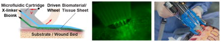
We demonstrate in situ formation of biomaterial and skin tissue sheets for application in vitro, and in murine and porcine wound models.
Introduction
Skin is the largest organ that provides a barrier to the total body surface area (TBSA), 1.6–2.0m2 in adults,1 and possesses a unique layered organization of cells and extracellular matrix (ECM) constituents.2 The viable epidermis is the thin (thickness δ~ 95μm, elastic modulus E~1.5MPa3) outermost cellular layer that consists of densely packed keratinocytes and provides a barrier against water loss and bacterial transport. Beneath it is the dermis (δ~ 1.4mm, E~0.02MPa3), populated by fibroblasts along with various other cell types and a dense extracellular matrix containing collagen,4 and the hypodermis (δ~ 0.8mm, E~0.002MPa3).
Patients with acute and complex full-thickness wounds are particularly vulnerable to opportunistic infections and dehydration. Full-thickness wounds where the dermis, epidermis, and hypodermis are all destroyed do not heal or take a long time to heal by reconstitution of dermis followed by re-epithelialization progressing from the wound edge.5 The current preferred treatment for full thickness wounds is split-thickness autografting.5, 6 In a first step of the procedure, an acellular scaffold may be applied to aid the reconstitution of the dermis and a temporary barrier is established against bacterial and water loss. In a second step that is often performed at a later time point, the temporary barrier is removed. Skin, usually 0.3mm in thickness, containing the epidermis and the upper part of the dermis is then harvested from healthy regions of the body using a handheld instrument, a dermatome, and redistributed onto the wound area as a sheet or meshed graft. In large wounds, the available healthy donor skin is often insufficient for autografting, leaving a large portion of the wounded area either ungrafted, allografted, or uncovered, resulting in poor outcomes.
A large number of acellular skin substitutes based upon biological or synthetic biomaterials have been introduced to improve wound healing in acute and chronic wounds.6, 7 An acellular dressing based on chemically cross-linked and freeze-dried collagen8 remains the ‘gold standard’ for clinical use. When covered with a split-thickness autograft it reduces wound contraction while promoting the migration of residual healthy cells and leads to the reconstitution of a new dermal layer within 2–3 weeks. Recent biomaterials options include mats of electrospun nanofibers. A wide range of tissue-engineered skin substitutes have been introduced, including cultured epithelial autografts.5 In addition, spraying cells onto partial-thickness9 and full-thickness10 acute wounds, as well as onto chronic wounds11 was reported to improve wound healing. Accelerated healing in murine wounds was recently reported for an injectable skin substitute composed of microgel particles and cells.12 In spite of the large number of available tissue-engineered skin substitutes, they are not yet widely used in the clinic. Currently, major barriers for routine clinical application of cell-based engineered skin substitutes for large acute wounds include the prohibitively long times for expanding sufficient cell numbers, their high cost, and the inability of tailoring them to specific wound sizes and characteristics. We hypothesize that a number of these barriers can ultimately be overcome by in-situ skin printing and introduce the approach along with its thorough characterization in this paper.
The spatial organization of biopolymers and cells is closely associated with biological organ function in health and disease. Additive manufacturing methods aim to recapitulate aspects of the spatial organization of cells and biopolymers in intact tissues. A shared motivation for many current studies is to elucidate the extent to which the initially provided tissue organization contributes to improving the functional characteristics of tissues after in vitro culture or in vivo application, as well as to accelerating tissue regeneration. Bioprinting approaches have been extended to soft materials13 and tissues.14–19 Different extrusion or ink-jet based bioprinters as well as microfluidic approaches for the formation of biopolymer fibers20–22 and sheets23 offer local control over the delivery of biopolymers and cells. Synthetic and natural biopolymers with different composition and cross-linking mechanisms serve as the ‘bioink’.24, 25 Target bioink properties include shear thinnening rheological behavior, rapid gelation, cell compatibility, and upon gelation a chemical composition and stiffness mimicking the microenvironment in the intact tissue of interest. Protein-based biomaterials including collagen I, the most abundant protein in the dermis, and fibrin, a protein involved in wound healing, make for obvious candidates as they are widely used in 3D cell culture as well as clinical settings.26, 27 Their “printability” however is poor, as the low viscosity of protein-based solutions and their long gelation times (>1 min) significantly exceed characteristic time scales of the bioprinting process.28 To improve printability, rapidly gelling biopolymers are often added.
Several recent examples have demonstrated bioprinted skin tissues in vitro,29–31 or in small animal models.32, 33 Important requirements for the routine in vivo application of bioprinted skin substitutes under conditions that are compatible with use in large animal models and ultimately the clinic are not yet met. They require the formation of routinely handleable larger skin tissues from composite materials while retaining a soft cellular microenvironment. One strategy that was recently demonstrated in other tissues34 and can likely be applied to skin is a sequential multimaterial approach, where the deposition of a backbone support structure from a biocompatible sacrificial material preceded the deposition of a bioink. A second strategy consists of the in-situ formation of organized biomaterial and skin tissue sheets along inclined or curved wound surfaces. This strategy has to the best of our knowledge not yet demonstrated and is the focus of our paper.
Here, we present an approach that enables bioprinting of planar biomaterials and skin tissue sheets compatible with in vivo application in large animals, and ultimately the clinic. Bioink solutions are spatially organized using a microfabricated cartridge and deposited directly onto a planar surface for in-vitro and in-vivo use and characterization. The cartridge deposits enzymatically or ionically cross-linked biopolymer or tissue sheets conformally onto flat or curved surfaces. Homogeneous and architected sheets are consistently formed and characterized in-vitro. Proof-of-concept demonstrations for in situ bioprinting in murine and porcine excisional wound models illustrate the compatibility of the approach with compliant wound surfaces.
Materials and Methods
Figure 1a shows a schematic that introduces the concept of in-situ bioprinting using the handheld Skin Printer. Cells (autologous or allogeneic) are suspended in a hydrogel precursor solution and loaded into one or several separate syringes. Another syringe contains a crosslinking solution that will aid the gelation of the cell-laden biopolymer solution under mild conditions (i.e., natural pH, physiological temperature) and high cell viability. After loading the primed syringes into the handheld bioprinter, the bioink is deposited as a biomaterial or tissue sheet within a culture dish for in-vitro studies, or directly onto a wound bed for in vivo studies. For example, bioink containing human fibroblasts can be homogeneously distributed within the 0.1–0.6mm thick dermal layer. Bioink containing keratinocytes may be deposited within parallel stripe patterns that are separated by cell-free stripes resembling a meshed epithelial skin graft.
Figure 1. Handheld Skin Printer.
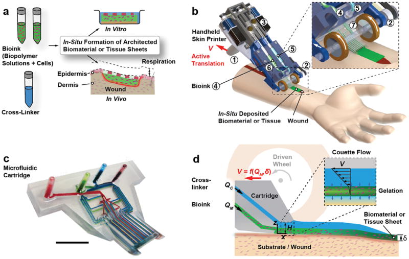
(a) Schematic diagram illustrating working principle of handheld bioprinter. One or several bio-ink solutions (green color), containing premixed biomaterials and cells, and a cross-linker solution (blue color) are prepared. Handheld bioprinter converts bio-inks into homogenous or architected biomaterial sheets or tissues directly within a culture dish or a wound site. (b) Rendered image of handheld bioprinter. A handle ➀ enables positioning above target surface or wound. A stepper motor, pulley and drive mechanism ➁ define the deposition speed, V. Two on-board syringe pump modules ➂ control the dispensing flow rates for bioink ➃ and cross-linker solution ➄. 3D printed microfluidic cartridge ➅ for spatial organization of solutions and sheet formation. (c) Photograph of 3D printed microfluidic cartridge. Scale bar 10 mm. (d) Schematic side-view image showing sheet formation between moving microfluidic cartridge and deposition surface or wound. Inset indicates fluid velocity profiles in bioink (green) and cross-linker layers (blue).
The handheld bioprinter is an integrated, lightweight instrument (weight < 0.8kg including loaded syringes) with a high degree of portability. It is straightforward to operate with only one hand and consists of several key parts that are shown in Fig. 1b. A handle, ➀, allows positioning the Skin Printer manually above a flat surface or wound bed. During deposition, a pair of actively driven rollers with rubber wheels, ➁, translates the instrument along the deposition surface at velocity V, while conformally coating it with a bioink sheet covered with cross-linker solution. Traction between the wheel and the deposition surface, determined by the friction coefficient and contact pressure,35 is important for smooth and definite translation speed and consistent deposition. During in vitro experiments, we deposit sheets horizontally, against agarose coated glass slides. During deposition in large animal models, both wheels are in contact with inclined and compliant surfaces of either intact skin or a wound. Two onboard syringe pumps36, ➂, deliver the bioink at volumetric flow rate QM, ➃, and the cross-linker solution at flow rate QC, ➄, irrespective of the bioink viscosity, the cell density and the instrument orientation. The bioink and cross-linker solutions are supplied to an exchangeable microfluidic cartridge, ➅, via flexible tube connections that have dead volumes less than 20 μl.
Microfluidic Cartridge
The microfluidic cartridge, the central part of the instrument (Fig. 1c, ESI Section S2), was 3D printed37 using an optically semi-transparent resin. Integrating standardized Luer lock connectors and on-chip wells within one 3D printed part allowed us to reduce unwanted dead volumes (~ 65 μl). The cartridge provides uniform lateral distribution of at least two solutions within microchannel networks located in separate planes. Cartridge designs had wo=8mm, 14mm, and 20mm wide exit sections. A H=1 mm tall slit defined between a short overhanging roof section on the top and the deposition surface on the bottom. Figure 1d schematically shows how a bioink layer of thickness δ< H and width w is deposited onto the surface while being covered by the cross-linking solution for cross-linking into a sheet. The position of the cartridge exit aligns in the lateral direction with the contact points between the drive wheels and the deposition surface. In this configuration the thickness of the sheet is only weakly dependent on the operator-selected angle at which the handheld printer is being held relative to the deposition surface. The formed sheet may be homogeneous or heterogeneous in composition. In the latter case, the spatial organization is determined by the microchannel configuration within the cartridge, along with the parameters selected for V, QM and QC.
Control Box
A control box is connected to the handheld Skin Printer via a pneumatic line and an electrical ribbon cable. The control box powers the instrument, controls the deposition velocity V, the flow rates QM and QC, and, in the case of pressure-controlled delivery, the head pressure and the duration of its application. For a detailed description of the design we refer to ESI Section S2.
Preparation of Agarose Substrate
A solution of 2% agarose (UltraPure Agarose, 16500100, Invitrogen) in de-ionized (DI) water was prepared by microwave heating. The solution was allowed to cool to 60˚C prior to being poured into sterile square petri dishes (model Z692344, Sigma Aldrich) and resulted in a 3-mm-thick gel. The gel solidified at room temperature for 30 min prior to use. For preparation of sodium alginate-based sheets, 50 mM calcium chloride (CCL302, BioShop) was added to the agarose solution prior to microwave treatment. For printing of fibrin-based sheets, 2 ml of 50 IU thrombin (T4648, Sigma Aldrich) in PBS (10010023, Gibco) was pipetted to hydrate the agarose substrate prior to sheet deposition.
Bioink Preparation
Bioinks with three different compositions were prepared. For alginate-collagen sheets, sodium alginate (Pronva UPLVG, Novamatrix) was dissolved in DMEM (11965-084, Gibco) and 20 mM HEPES (15630080, Gibco) and filtered using 0.1μm syringe microfilter (Millipore). Collagen type 1 (rat tail, 354249, Corning) was balanced to a pH of 7 using 1 M NaOH in PBS. The two stock solutions were mixed to obtain a final concentration of 5 mg/ml collagen and 2 % alginate. The solution was kept on ice prior to use. To prepare the bioink for the dermal layer 5% fibrinogen (F8630, Sigma) was dissolved at 37˚C in PBS with mild agitation for 2 h. 1% HA (sodium hyaluronate Pharma Grade 80, Novamatrix) was dissolved in PBS. The solutions were mixed at a ratio of 1:1 and then filtered. Collagen type 1 solution was balanced with NaOH to a pH of 7 and mixed with the filtered fibrin/HA solution to obtain a final concentration of 1.25% fibrinogen, 0.25% HA and 0.25% collagen. The solution was kept on ice prior to use. The bioink for the epidermal layer was prepared with a final concentration of 2.5% fibrinogen and 0.25% HA. ESI Table S1 summarizes the composition of materials used for the preparation of the bioinks.
For printing the fibrin-based sheets, a layer of 50 IU thrombin was co-delivered above the fibrinogen based dermal and epidermal bioinks. The rapid enzymatic reaction between fibrinogen and thrombin is mass transfer limited in the considered case. The selected approach allowed the formation of sheets on the site of the deposition which solidified at time scales between tens of seconds and several minutes, depending on the selected thrombin concentration and sheet thickness, δ. The gelation time is directly dependent on the sheet thickness (Fig. 2e). For the dermal bioink consisting of a mixture of collagen and fibrinogen, the gelation of fibrinogen occurs first and is induced by the diffusion of thrombin. As a result, the sheet thickness and composition are maintained while the slower thermally induced gelation of neutral pH collagen progresses.
Figure 2. In-situ Deposition of Homogeneous and Layered Hydrogel Sheets.

(a) Comparison of side view images after manual deposition of 100μl fibrin/HA bioink droplet (left) and sheet deposited using handheld bioprinter (right). Agarose substrates hydrated with cross-linker solution used in both cases. Images acquired at 4˚ angle. (b) Representative optical profilometry image and cross-sectional view of δ=300μm sheet printed with 14mm wide microfluidic cartridge. (c) Measurement and model predictions for dimensionless sheet thickness, δ*=δ/H, as function of dimensionless bioink flow rate, QM*=QM (w0VH)−1. (d) Analytical solution for velocity distribution within confinement. (e) Characterization of gelation kinetics based on measurement of time-dependent changes in normalized turbidity of fibrin-based sheets with different thicknesses. (f) Microstructure characterization using scanning electron microscopy, (g) Young’s modulus and (h) elongation at break, for sheets consisting of fibrin-HA/collagen I, fibrin-HA, collagen I-alginate and alginate. (i) Confocal image of bi-layer sheet prepared by subsequent deposition of 200μm thickness alginate layer containing FITC microparticles (bottom) and 100μm thickness alginate layer containing Nile red microparticles (top). (j) Confocal image of three-layer sheet prepared by subsequent deposition of 500μm (bottom) fibrin-HA layer with blue micropartices, 200μm (middle) alginate-collagen layer with FITC-conjugated collagen and 150μm (top) alginate layer with Nile red microparticles. Scale bars 2mm (a left), 5mm (a right), 2μm, 10μm, 1μm, 1μm (f, from left to right), 100μm (i, j)
The alginate and alginate-collagen based sheets were prepared by co-delivery of 10 mM calcium chloride above the biopolymer layer. Similarly, rapid ionic cross-linking of alginate preceded the slower thermal gelation of neutral pH collagen.
In Vivo Experiments
The animal experiments were reviewed and approved by and performed in accordance with the guidelines and regulations set forth by the Sunnybrook Research Institute and Sunnybrook Health Sciences Animal Policy and Welfare Committee of the University of Toronto, Ontario Canada. All procedures using animals were approved by the Sunnybrook animal care committee, approval #17-503 for murine experiments and #17-600 for the porcine experiments under the auspices of the Canadian Council on Animal Care. For a more detailed description of experimental and characterization methods see ESI Section S1.
Results and Discussion
Single and Multilayered Biomaterial Sheets
Figure 2a shows a bright field image of a sheet with the uniform thickness of δ=300μm produced with the handheld Skin Printer (right) in comparison with a non-uniform thickness pattern obtained by manually pipetting a comparable amount of the same hydrogel precursor (left). Both images were taken at an angle of 4˚ with respect to the flat deposition surface consisting of an agarose layer that was hydrated with the cross-linker solution. In the latter case, the pipetted hydrogel assumed a dome shape. Uniform spreading of the biopolymer solution was prevented by gelation starting along the contact line and then radially progressing inward. In the former case of the printed hydrogel sheet, however, gelation uniformly progressed in the direction normal to the deposition surface. This was achieved by first delivering the hydrogel precursor solution through a bifurcating microchannel network. At each bifurcation point within the 3D printed microchannel network, the hydraulic diameter of the daughter branches decreased in accordance with Murray’s law. For more detail see ESI Section S2. The bifurcated channel network ensures the flow resistance in the smallest daughter channels at the device exit to be high and leads to a constant thickness biopolymer layer to be deposited. A cross-linker layer was co-delivered atop to initiate gelation. Figure 2b shows a profilometer reading that confirms a consistent thickness in the >0.9w center portion of the obtained sheet.
Next, we discuss how the different experimental parameters affected the sheet thickness δ. We consider the laminar flow of a layered fluid between the two surfaces and apply the lubrication approximations.38 Because w0/H > 10 we approximate the hydraulic diameter as 2H. We neglect the pressure gradient in the z-direction as well as inertia effects (see ESI Section S3). The continuity equation and the simplified momentum balance result in a single elliptic differential equation, the Reynolds equation, for the pressure gradient along the film. An analytical model is derived and presented in ESI Section S3. The model allows predicting δ based on the fluid viscosities μM and μC, and the flow rates of the biopolymer and the cross-linker solutions, QC and QM (Fig. 2c). The corresponding dimensionless quantities are and . For given values of the dimensionless sheet thickness, μ*, the dimensionless flow rates QM* and QC* are selected in such a way that the pressure is is invariant along the deposition direction, i.e., . At the selected condition, unwanted bioink back flow or leakage to at the sides of the cartridge are avoided during deposition. The dimensionless bioink and cross-linker flow rates required to obtain a target sheet thickness δ* are
Figure 2d shows the corresponding velocity profiles. In many cases the viscosity of the cross-linker is much lower than the one of the biopolymer solution, μ* ~ 0, leading to the linear relationships and QC* = 0.5(1 − δ*). Note that the relationship is fulfilled even in the case of a very short or absent overhanging roof structure at the cartridge exit section.
The analytically predicted sheet thickness is in excellent agreement with values measured for bioprinted fibrin-based and alginate-based sheets. Sheet thicknesses between δ=100μm and 600μm were reliably obtained using a microfluidic cartridge with H=1mm. Thicker sheets, δ > 600μm, were achieved by sequential deposition of multiple thinner sheets. Sequential deposition is preferred over extruding thicker sheets in a one-step process using a modified cartridge design with H>1mm. The latter would increase the diffusion time, ~δ2/4, and consequently the time required for gelation, and make the sheet thickness dependent on the inclination angle of the deposition surface.
The handheld bioprinter is compatible with different biopolymers. In the presented work we consider the polysaccharide-based biopolymer calcium alginate, and the protein-based biopolymer fibrin. The compositions of the different considered bioinks and cross-linker compositions are summarized in ESI Table S1. Selected bioink choices are highly biocompatible, biodegradable, provide a cellular microenvironment conducive to cell proliferation and attachment, and do not require secondary washing steps prior to in-vitro culture or direct in-vivo application.
Understanding the kinetics of gelation within the deposited bioink layers is crucial for the in-situ deposition of tissues. In the considered cases, gelation is a diffusion-limited process that is initiated at the interface between the bioink and cross-linker layers and propagates throughout the former. For alginate-based sheets, gelation is induced via rapid ionic cross-linking by diffusion of Ca2+-ions from above.39 Gelation of fibrinogen is induced by an enzymatic reaction with thrombin. Gelation is slower in this case because the process is diffusion limited, and the diffusivity of thrombin is at a comparable viscosity approximately ten times smaller than the one of Ca2+-ions. In order to retain the deposited layer thickness and sheet architecture while gelation progresses, we increased the viscosity of the fibrinogen-based bioink by adding hyaluronic acid. We assessed the kinetics of gelation by performing systematic turbidity measurements. Figure 2e shows data from time-resolved turbidity measurements performed on in-situ deposited fibrin-HA sheets with thicknesses of δ = 100 μm, 200 μm, 400 μm and 600 μm. Gelation was induced by inter-diffusion of thrombin and calcium chloride contained in the cross-linker stream above, and in the agarose-coated deposition surface below. The in-situ turbidity measurements reveal the gelation times (Estimated as the inflection point on the turbidity graph) is tg ~ 44 s, 64 s, 110 s and 160 s for sheet thicknesses of δ=100 μm, 200 μm, 400 μm and 600 μm. As we will discuss in more detail below, rapid enough gelation is an important requirement for in-situ formation of sheets on inclined or compliant surfaces.
Figure 2f shows representative scanning electron microscopic (SEM) images to characterize the surface microstructure of sheets that were obtained from the different bioinks. As the sheets are small in thickness (100 – 600 μm), we don’t expect large non-homogeneities in pore size and microstructure across the sheet thickness.40 Figures 2g–h show the Young’s moduli and elongations at break of in-situ formed sheets, respectively. Tensile properties were evaluated for the hydrated sheets along the direction of deposition, x. At the selected processing conditions, alginate-based sheets exhibited higher Young’s moduli, compared with fibrin-based ones. The latter has a higher elasticity and a 2.6 times higher elongation at break (at constant strain).
To obtain multilayered sheets of controllable thickness, multiple sheets may be consecutively deposited using the handheld Skin Printer. In addition to depositing multiple sheets of the same composition, the stepwise approach enables the biopolymer or the cellular composition to be altered between layers. Figures 2i–j show confocal micrographs of multilayered sheets that were sequentially obtained. To achieve the three-layered sheet shown in Fig. 2j the following three layers were deposited from bottom to top: a 500μm layer of fibrin containing 0.1μm polystyrene particles (blue color); after 5 min a 200μm layer of alginate containing FITC conjugated collagen type 1; and after another 30min a 150μm layer of alginate containing 0.2μm polystyrene particles (conjugated with Nile red).
Architected Biomaterial and Tissue Sheets
We now consider microfluidic bioprinter cartridges that aid the formation of single-layered biomaterial or tissue sheets with a composition that varies along either the lateral or the extrusion direction. As schematically shown in Fig. 3a and Video ESI S1, architected sheets were obtained by independently controlling the flow rates of a primary bioink, QM1 (indicated by green color), and a secondary bioink, QM2 (indicated by red color) as delivered from the two on board syringe pumps. The cross-linker was supplied from an external syringe pump. The design of the microfluidic cartridge was adapted from one that we had previously used for the formation of stripe-patterned sheets without substrate support.23 We incorporated four equidistant stripes of a secondary biopolymer within the primary biopolymer. As shown in Figs. 3b and 3c we decreased the relative stripe width, w2/w0, by increasing the relative rate at which the secondary bioink was supplied compared with the primary one, QM2/QM1, while keeping the total bioink flow rate, QM2 + QM1, unchanged. Stripes narrower than the width of the smallest channel features of the microfabricated cartridge were obtained by hydrodynamically focusing41 the secondary bio-ink within the biopolymer feature layer of the microfluidic cartridge. In the examples presented so far, the primary and secondary bioink solutions shared the same composition but differed in their payload. However, primary and secondary bioink solutions with different composition may also be used as long as their cross-linking mechanisms are compatible. For example, single-layered sheets with alternating composition were obtained by co-flowing two different bioink solutions in-plane. Figure 3d shows a representative sheet with alternating alginate and fibrin-HA stripes deposited on an agarose substrate coated with calcium chloride and thrombin.
Figure 3. In-situ 3D Bioprinting of Architected Sheets.

(a) Schematic of biomaterials and cells organized into stripe patterns using microfluidic cartridge. (b) Representative confocal image of stripe-patterned monolayer. (c) Relative stripe width wstripe/w0 as function of flow rate ratio. (d) Representative multi-material organization of sheets with alternating fibrin-HA (red color) and alginate (green color) stripes. (e) Schematic of biomaterials and cells organized into spotted patterns using pressure-controlled reservoir. (f) Representative images for pressure-controlled spotting. (g) Spot volume as function of reservoir head pressure during 0.2s actuation. (h) Estimated nominal in-plane resolution for forming fibrin-HA sheet onto flat but inclined surfaces, (inclination angle θ). Initial stripe resolution as obtained from 3D printed cartridge without (*) and with flow focusing feature (**) (i) Schematic of biomaterials and cells organized into undulated sheets or parallel fibers using microfluidic cartridge. (j) Representative bright-field image of undulated sheet with 8 peaks. Image captured at 4 degrees. Insert shows enlarged image of two neighboring peaks at 2 degrees. (k) Confocal image of cross-section of an undulated sheet with 4 peeks. (l) Representative reconstructed confocal image of bi-layered sheet cross-section. Bottom layer (green color) homogenous, top layer consists of 4 parallel stripes (red color). (m) Meshed pattern formed by successive deposition of 8 parallel stripes perpendicular to one another. Scale bars 2mm (b), 500μm (d), 6mm (f), 5mm (j), 200μm (k, l), 4mm (m).
In addition, we formed sheets where spots of the secondary bioink were incorporated within the primary bioink. The secondary bioink was delivered from a well that was incorporated at the inlet of the 3D printed microfluidic cartridge, where a time-dependent head pressure was applied (Fig. 3e). We delivered the primary bioink at a flow rate, QM1, and applied a square-wave pressure signal. The frequency and the duty cycle of the pressure affected the spot volumes, as well as the distance between spots. For a fixed QM1, frequency and duty cycle, increasing the amplitude of the head pressure decreased the distance between subsequent spots and increased the spot volume (Fig. 3f and 3g). We analytically estimated the attainable resolution of the deposition process (Fig. 3h, ESI Section S5) depending on the inclination of the deposition surface, and the gelation kinetics. As the sheet thickness increases, the permitted drainage time scale for in situ formation of sheets with a desired spatial resolution decreases, and the gelation time increases. The permitted drainage time decreases with increasing inclination angle.
The in-situ formation of substrate-adhesive undulated sheets or arrays of parallel stripe filaments is schematically shown in Fig. 3i and extends the attainable sheet morphologies. One cross-linker solution serves as the flow-confining fluid and is referred to as the primary cross-linker solution and delivered to the microfluidic cartridge from an external syringe pump. The bioink is delivered by one of the on-board syringe pumps. A secondary cross-linker solution is delivered from the other on-board syringe pump, and distributed within the biopolymer feature layer. As a result, stripes of the secondary bioink and the cross-linker solutions are deposited in alternating fashion along the lateral direction. For slow gelation or a low viscosity of the cross-linker solution, the stripe-patterned bioink spreads laterally until gelation is completed, producing undulated sheets (Figs. 3j–k). For more rapid gelation, or an increased viscosity of the cross-linker solution, the relaxation time due to the density difference between the biopolymer and cross-linker solutions is shorter than the gelation time. An array of parallel substrate-attached biopolymer filaments is obtained. Figure 3l shows an array of such stripe-filaments that was deposited in a single pass on top of a homogeneous sheet. The filaments are disconnected in the lateral direction. A mesh pattern as shown in Fig. 3m was obtained in a case when another stripe array was deposited in a second pass perpendicularly to a previously deposited one.
In-vitro Application of Handheld Skin Printer
The bioink used for in vitro experiments contained hyaluronic acid, fibrinogen, and type-I collagen. Gelation of the fibrinogen component was induced by the enzymatic activity of thrombin at neutral pH and room temperature. Hyaluronic acid was added to increase the viscosity and “printability” of the bioink, without adversely impacting cell viability. Selected deposition conditions are characterized by low shear rates (on the order of 1 s−1) that are not expected to affect cell viability or function. Figures 4a–b show that human dermal fibroblasts (FB) embedded in the fibrin-based sheets exhibited >90% viability based on a live/dead assay performed after 10 days in culture. At day 0, we investigated five different cell concentrations that ranged from 0.1 to 10 million/ml, and found the original cell seeding density in the bioink to be consistent with the cell density assessed within the planar tissue, based on Hoechst nuclear staining and confocal microscopy (for more detail see ESI Section S1). No cell or biomaterials clumps or aggregates were observed immediately after sheet formation, indicating the delivered cells to remain uniformly dispersed within the planar tissue (ESI Figure S12). Cell numbers were quantified using a Hoechst nuclear stain and confocal microscopy and demonstrated the increase in total cell numbers over a three-day culture period, suggesting continued cell growth and proliferation (Fig. 4c).
Figure 4. In-vitro Characterization of in-situ Bioprinted Tissues.

(a) Homogenous printed sheet contains human dermal fibroblasts (FBs). Live cells indicated by calcein stain (green). Dead cells indicated by fluorescent ethidium homodimer-1 (red). (b) Quantitative assessment of FB viability in printed fibrin/HA/collagen-I bioink with >90% cell viability during 10-day culture. (c) Quantitative assessment of FB and KC cell numbers as an indication of cells proliferation over 3 days of in-vitro culture. (d) FBs deposited within the bioink containing 1.25% fibrin, 0.25%collagen I, 0.25% HA and stained with Hoechst (blue) and phalloidin (green) show excellent attachment and elongation during 12 hr. (e) Comparison between day 0 and day 3 of human keratinocytes (KCs) deposited in fibrin gel using immunofluorescent staining for cell nucleus (blue), actin (green), and keratin-14 (red) indicating cell grouping and clustering by day 3. (f) Deposited monolayer sheet containing KCs in stripe patterns as visualized using phalloidin immunostaining on day 0. (g) Bilayer construct printed in stepwise fashion Keratinocytes (k14 & phalloidin co-stain, red) sequentially deposited on top of FBs (phalloidin, green) resembling bi-layered structure of skin. Scale bars 200 μm (a,g), 100 μm (d, e), 2 mm (f).
To assess FB attachment and morphology, we selected a bioink containing human dermal FBs in a fibrinogen-collagen-HA solution. At time points 0, 3, 6 and 12 hr post printing, sheets were fixed and stained for nuclei and cytoskeleton. The results suggest the cells are adapting to the 3D scaffold without impacting morphology, as they exhibit elongation and attachment within the first few hours after sheet formation (Fig. 4d).
Keratinocytes (KCs) are the essential cell component of the skin epidermal layer. A bioink consisting of 1.25 million human KC/ml in a mixture of fibrinogen and HA was used to form a 200μm thick sheet. Collagen-I was not added to better mimic the epidermal layer undergoing wound repair, to accelerate the degradation of the biomaterial matrix, and thereby reduce cell-cell distances and aid KC cluster formation. On day 0, the cells were dispersed individually and homogeneously distributed within the sheet (Fig. 4e, top row). Within three days of 3D culture, KCs formed clusters as shown in confocal micrographs, suggesting adhesion of KCs and the formation of colonies, characteristics of a normal epithelial activity42 (Fig. 4e, bottom row).
We obtained cell-laden stripe patterns in vitro, by adding KCs to the secondary bioink as shown in Fig. 4f. The width and distance of the stripes is governed by tuning the volumetric flow rates of the secondary bioink, QM2, and the cross-linker, QM1. The w0=8mm wide cartridge produced equidistant stripes of width w2=500μm that were imaged by using phalloidin staining.
To mimic the layered architecture of skin, a bi-layered sheet containing both keratinocytes (KCs) and human dermal FBs was deposited (Fig. 4g). First, a 500μm thick layer was formed from a bioink that contained 4×10⁵ FBs/ml in a collagen/fibrinogen precursor solution. Second, a 100μm layer of KCs embedded within a fibrinogen/HA precursor solution was deposited on top. Immunostaining of the bi-layered construct specific for F-actin (Phalloidin green) and keratin-14 (anti-K14, red) to visualize dividing basal keratinocytes revealed cell compartmentalization in a stratified structure with two distinct cell populations (phalloidin green, K14 red).
In-vivo Application of Handheld Skin Printer
We demonstrate the in vivo formation of architected sheets. A murine wound model served as an example of a compliant and curved surface that undergoes periodic respiratory motion. We characterized in-situ sheet deposition by a combination of fluorescence and bright-field imaging during and immediately after deposition. Mice were sacrificed 1 hour after deposition. Figures 5a and 5b show wide-field fluorescence images of in-situ formation of a biopolymer fiber array onto a 8 mm diameter excisional wound, which is particularly challenging because it requires the consistent sheets to be formed at a short distance while deposition onto a curved and compliant wound surface. The deposited stripe-patterned sheets or stripe arrays remained firmly attached to the wound and periodically followed respiratory cycles, or manual tissue deformation (Fig 5c). To improve contrast during imaging, we added green fluorescent microparticles to the secondary bioink. ESI Figure S11 shows images for the synchronous formation of stripe-arrays prepared from either alginate or fibrin-HA onto an excisional wound located at the back of a mouse. Stripe arrays prepared in fibrin-HA are less distinct compared with the alginate case, a difference that we attribute to the slower gelation in the former case (Fig. 5d).
Figure 5. In-vivo Compatibility of in-situ Bioprinting in Small and Large Animal Models.

(a) Fluorescent image of stripe-patterned sheet formation directly onto murine excisional wound. (b) Representative image of 4 stripes in-situ deposited onto 8mm wound model. Dashed circle indicates wound edge and arrow indicates initiation phase. (c) Striped sheets remain adherent to wound bed during respiration or stretching, and the printed geometry retains its shape. 1μm green fluorescent microparticles incorporated as payload (a, b, c). (d) representative normalized fluorescence intensity across striped alginate sheet (solid line) and fibrin sheet (dashed line) in-situ formed on the back of a murine excisional wound. (e) Representative photograph showing in situ deposition of δ=250 μm thick fibrin-HA/collagen sheet on top of a full thickness excisional porcine wound using handheld Skin Printer. (top); Close-up view of sheet formation within wound bed with a 2cm microfluidic cartridge. (bottom) (f) (Control, not printed) on day 0 and Printed 5 min after in-situ formation of biomaterial sheet. (g) Trichrome staining indicating the extent of granulation tissue formation and reepithelialization. Arrows indicate the border between newly formed granulation tissue and intact skin. Arrowheads marks epithelialized area. Arrowhead at the center of treated wound shows complete re-epithelialization, while central arrowhead in control wound shows non re-epithelialized zone at wound center. Scale bars 2mm (a, b, c, g left), 10mm (h), 1mm (g right).
Finally, we selected a porcine wound model in a proof-of-principle demonstration of in-situ depositing a homogenous hemostatic barrier on an excisional wound under clinically relevant conditions. Wounds were marked on the back of the animal before the operation. For pain control, animals received a basic dosage of tramadol (4–6mg/kg) which may escalate when needed on the day of the surgery until euthanization. After the excision, 20mm×40mm full-thickness excisional wounds were covered by direct deposition of a homogenous fibrin-HA sheet (δ=300μm, w=20mm, Figs. 5e). We compared to a contralateral wound without deposited sheet (4 wounds as control on same animal, video ESI S2). Bleeding stopped after approximately 5min in the wounds covered by the in-situ deposited sheets while control wounds achieved hemostasis after tens of minutes (Fig 5f). Microscopic analysis of H&E staining on cross-sectional samples of the harvested healed wounds sacrificed on day 20 revealed that both treated and control wounds formed complete granulation tissue as indicated by the continuous red-stained region connecting the wound edges, and exhibited comparable levels of collagen deposition and cellularity as shown by the underlying purple region populated homogenously by dark blue cell nuclei (Fig. 5g). Only 1 out of the 4 control wounds showed complete re-epithelialization while 3 out of 4 treated wounds exhibited complete re-epithelialization (non-significant parametric test) (ESI Fig. S13). Healed wounds were stained with Keratin 10, an epithelial differentiation marker (ESI Fig. S14a), and with alpha-smooth muscle actin, a transient myofibroblast marker (ESI Fig. S14b), where no significant difference was observed between treated wounds and controls. The selected bioinks did therefore not inhibit granulation tissue formation or re-epithelization.
Summary and Conclusions
We presented a handheld bioprinter for the formation of biomaterial and tissue sheets with local control over biomaterial composition, and colloidal or cellular payload. The approach requires minimal operator training for the in-situ formation of biomaterial and tissue sheets onto either flat surfaces (in-vitro) or wound beds (in-vivo). The approach side steps the washing and incubation steps, scanning of wound surfaces or multi-axis printhead translation that would otherwise be required by many conventional bioprinters. Fragile sheets that correctly mimic the soft microenvironment of many cells can be in situ delivered for in vivo application.
We reported conditions for consistent sheet deposition using bioinks that consisted of alginate, fibrin, collagen and hyaluronic acid. The biopolymer solution was pre-mixed with cells prior to deposition to deliver cells in a controlled and cytocompatible manner and promote cell interaction with the surrounding microenvironment.43 Depending on the selected cartridge width and deposition velocity we rapidly covered deposition surfaces at rates of 0.3–1.6 cm2/s, exceeding characteristics of most extrusion-based bioprinters by at least one order of magnitude. additionally, we demonstrated different sheet morphologies including stripes, spots and meshes. The capacity of bioprinting undulate sheets may in the future allow mimicking the periodic protrusions (wavelength 50–400μm, amplitude 50–200μm) that separates the epidermal layer from the dermal layer of intact skin in the bioprinting process. These protrusions have been shown to increase the contact area, improve adhesion between layers, influence epidermal cell proliferation and migration, and decrease the chance of scar formation.44, 45
A first proof-of-concept experiment was conducted in a murine wound model with the goal of demonstrating the in-situ deposition of an architected sheet in the form of a fiber array onto a small and compliant wound surface. In a second a proof-of-concept study we evaluated in a porcine full thickness wound model the feasibility of using the handheld Skin Printer for in-situ biopolymer sheet deposition in a clinically relevant setting. A hemostatic biopolymer sheet (without cell load) was in-situ fabricated. Wounds where monitored for 20 days and histological end point analysis was performed. The porcine model demonstrated successful in-situ bioprinting to cover full thickness wounds with a homogeneous layer that provided a non-detrimental hemostatic barrier immediately after application where it did not impede normal re-epithelization or wound contraction. Four porcine full thickness wounds with sizes of 2 cm × 4 cm (1.24 in2) were covered with a δ=0.3mm thick and 20mm wide sheet. The current instrument accommodates up 3 ml of bioink solution, which allows at the selected conditions the continuous coverage of ~100 cm2 (15.5 in2) during 0.8–2.1min. Covering significantly larger areas with homogeneous sheets will require the bioink volume per filling to be increased. Comprehensive in-vivo experiments will be required to assess wound healing of in-situ deposited skin tissue sheets.
We expect the presented approach to be widely applicable for the delivery of different natural and synthetic biopolymers solutions as well as differentiated and non-differentiated cells.
Supplementary Material
Acknowledgments
Helen Han Ming and Caiden Chih produced 3D rendered images. Shashi Malladi assisted with the in-vivo experiment and wound dressing changes in the porcine experiment. Kavin Kowsary took bright field photographs of the microfluidic device and the in-vivo experiments and recorded supplementary videos. We acknowledge an NSERC postgraduate fellowship (NH), a Barbara and Frank Milligan graduate fellowship (NH), Weber and Mariano Graduate Scholarship (NH), a MITACS fellowship (RC), a fellowship of the NSERC Training Program Organ-on-a-Chip Engineering & Entrepreneurship (RC), and the endowed Wallace G. Chalmers Chair in Engineering Design (AG). We are grateful for grant support from NSERC DC and DAS (AG), Grand Challenges Canada (AG, MGJ), Medicine by Design (Transition Award, AG; Seed Grant, SAN, MGJ), CIHR (123336, MGJ), NIH RO1 (2R01GM087285-05A1, MGJ), CFI Leader’s Opportunity Fund (25407, MGJ) and a generous donation from Toronto Hydro (MGJ). Device fabrication was performed at the Centre for Microfluidic Systems in Chemistry and Biology. In vitro and animal studies were performed at the Sunnybrook Research Institute.
Footnotes
Author contributions
N.H., L.L., S.A.N., M.G.J and A.G. designed the research. N.H. conducted the experiments and analyzed data. M.S. and N.H. designed, machined, assembled and tested the handheld Skin Printer and control box. N.H. designed the microfluidic cartridge. N.H. and P.Q.B developed analytical models and performed sheet thickness measurements. R.C. performed SEM. S.A.N. and M.G.J supervised in-vivo experiments. R.C. and N.B. assisted with in-vitro and in-vivo experiments. N.B. and S.A.N. analyzed in-vivo results. N.H. and A.G. wrote the manuscript. R.C., L.L, S.A.N., and M.G.J, reviewed the manuscript.
References
- 1.Mosteller RD. N Engl J Med. 1987;317:1098. doi: 10.1056/NEJM198710223171717. [DOI] [PubMed] [Google Scholar]
- 2.Watt FM. Science. 2014;346:937–940. doi: 10.1126/science.1253734. [DOI] [PubMed] [Google Scholar]
- 3.van Kuilenburg J, Masen MA, van der Heide E. P I Mech Eng J-J Eng. 2013;227:349–361. [Google Scholar]
- 4.MacNeil S. Nature. 2007;445:874. doi: 10.1038/nature05664. [DOI] [PubMed] [Google Scholar]
- 5.Shevchenko RV, James SL, James SE. J R Soc Interface. 2010;7:229–258. doi: 10.1098/rsif.2009.0403. [DOI] [PMC free article] [PubMed] [Google Scholar]
- 6.Supp DM, Boyce ST. Clin Dermatol. 2005;23:403–412. doi: 10.1016/j.clindermatol.2004.07.023. [DOI] [PubMed] [Google Scholar]
- 7.Jones I, Currie L, Martin R. Br J Plast Surg. 2002;55:185–193. doi: 10.1054/bjps.2002.3800. [DOI] [PubMed] [Google Scholar]
- 8.Yannas I, Burke J, Orgill D, Skrabut E. Science. 1982;215:174–176. doi: 10.1126/science.7031899. [DOI] [PubMed] [Google Scholar]
- 9.Gerlach JC, Johnen C, Ottomann C, Bräutigam K, Plettig J, Belfekroun C, Münch S, Hartmann B. The International Journal of Artificial Organs. 2011;34:271–279. doi: 10.5301/ijao.2011.6508. [DOI] [PubMed] [Google Scholar]
- 10.Navarro F, Stoner M, Park C, Huertas J, Lee H, Wood F, Orgill D. Journal of Burn Care & Research. 2000;21:513. doi: 10.1097/00004630-200021060-00007. [DOI] [PubMed] [Google Scholar]
- 11.Falanga V, Iwamoto S, Chartier M, Yufit T, Butmarc J, Kouttab N, Shrayer D, Carson P. Tissue engineering. 2007;13:1299–1312. doi: 10.1089/ten.2006.0278. [DOI] [PubMed] [Google Scholar]
- 12.Griffin DR, Weaver WM, Scumpia PO, Di Carlo D, Segura T. Nature materials. 2015;14:737–744. doi: 10.1038/nmat4294. [DOI] [PMC free article] [PubMed] [Google Scholar]
- 13.Truby RL, Lewis JA. Nature. 2016;540:371–378. doi: 10.1038/nature21003. [DOI] [PubMed] [Google Scholar]
- 14.Murphy SV, Atala A. Nature Biotechnology. 2014;32:773–785. doi: 10.1038/nbt.2958. [DOI] [PubMed] [Google Scholar]
- 15.Liu WJ, Zhang YS, Heinrich MA, De Ferrari F, Jang HL, Bakht SM, Alvarez MM, Yang JZ, Li YC, Trujillo-de Santiago G, Miri AK, Zhu K, Khoshakhlagh P, Prakash G, Cheng H, Guan XF, Zhong Z, Ju J, Zhu GH, Jin XY, Shin SR, Dokmeci MR, Khademhosseini A. Advanced Materials. 2017:29. doi: 10.1002/adma.201604630. [DOI] [PMC free article] [PubMed] [Google Scholar]
- 16.Colosi C, Shin SR, Manoharan V, Massa S, Costantini M, Barbetta A, Dokmeci MR, Dentini M, Khademhosseini A. Advanced Materials. 2016;28:677–684. doi: 10.1002/adma.201503310. [DOI] [PMC free article] [PubMed] [Google Scholar]
- 17.Norotte C, Marga FS, Niklason LE, Forgacs G. Biomaterials. 2009;30:5910–5917. doi: 10.1016/j.biomaterials.2009.06.034. [DOI] [PMC free article] [PubMed] [Google Scholar]
- 18.Kolesky DB, Homan KA, Skylar-Scott MA, Lewis JA. Proc Natl Acad Sci U S A. 2016;113:3179–3184. doi: 10.1073/pnas.1521342113. [DOI] [PMC free article] [PubMed] [Google Scholar]
- 19.Kolesky DB, Truby RL, Gladman AS, Busbee TA, Homan KA, Lewis JA. Advanced Materials. 2014;26:3124–3130. doi: 10.1002/adma.201305506. [DOI] [PubMed] [Google Scholar]
- 20.Di Bella C, Duchi S, O’Connell CD, Blanchard R, Augustine C, Yue Z, Thompson F, Richards C, Beirne S, Onofrillo C. Journal of Tissue Engineering and Regenerative Medicine. 2017 doi: 10.1002/term.2476. [DOI] [PubMed] [Google Scholar]
- 21.Han YL, Hu J, Genin GM, Lu TJ, Xu F. Scientific reports. 2014:4. doi: 10.1038/srep04872. [DOI] [PMC free article] [PubMed] [Google Scholar]
- 22.Onoe H, Okitsu T, Itou A, Kato-negishi M, Gojo R, Kiriya D, Sato K, Miura S, Iwanaga S, Kuribayashi-Shigetomi K, Matsunaga YT, Shimoyama Y, Takeuchi S. Nature Materials. 2013;12:584–590. doi: 10.1038/nmat3606. [DOI] [PubMed] [Google Scholar]
- 23.Leng L, McAllister A, Zhang B, Radisic M, Günther A. Advanced Materials. 2012;24:3650–3658. doi: 10.1002/adma.201201442. [DOI] [PubMed] [Google Scholar]
- 24.Hospodiuk M, Dey M, Sosnoski D, Ozbolat IT. Biotechnology Advances. 2017;35:217–239. doi: 10.1016/j.biotechadv.2016.12.006. [DOI] [PubMed] [Google Scholar]
- 25.Malda J, Visser J, Melchels FP, Jungst T, Hennink WE, Dhert WJA, Groll J, Hutmacher DW. Advanced Materials. 2013;25:5011–5028. doi: 10.1002/adma.201302042. [DOI] [PubMed] [Google Scholar]
- 26.Balceniuk MD, Wingate NA, Krein H, Curry J, Cognetti D, Heffelfiner R, Luginbuhl A. Otolaryngol Head Neck Surg. 2016;155:76–80. doi: 10.1177/0194599816634616. [DOI] [PubMed] [Google Scholar]
- 27.Yoshida H, Hirozane K, Kamiya A. Biol Pharm Bull. 2000;23:313–317. doi: 10.1248/bpb.23.313. [DOI] [PubMed] [Google Scholar]
- 28.Jin YL, Liu C, Chai W, Compaan A, Huang Y. ACS Appl Mater Interfaces. 2017;9:17456–17465. doi: 10.1021/acsami.7b03613. [DOI] [PubMed] [Google Scholar]
- 29.Cubo N, Garcia M, Del Canizo JF, Velasco D, Jorcano JL. Biofabrication. 2016;9:015006. doi: 10.1088/1758-5090/9/1/015006. [DOI] [PubMed] [Google Scholar]
- 30.Lee V, Singh G, Trasatti JP, Bjornsson C, Xu X, Tran TN, Yoo SS, Dai G, Karande P. Tissue Eng Part C Methods. 2014;20:473–484. doi: 10.1089/ten.tec.2013.0335. [DOI] [PMC free article] [PubMed] [Google Scholar]
- 31.Pourchet LJ, Thepot A, Albouy M, Courtial EJ, Boher A, Blum LJ, Marquette CA. Adv Healthc Mater. 2017:6. doi: 10.1002/adhm.201601101. [DOI] [PubMed] [Google Scholar]
- 32.Koch L, Deiwick A, Schlie S, Michael S, Gruene M, Coger V, Zychlinski D, Schambach A, Reimers K, Vogt PM, Chichkov B. Biotechnol Bioeng. 2012;109:1855–1863. doi: 10.1002/bit.24455. [DOI] [PubMed] [Google Scholar]
- 33.Michael S, Sorg H, Peck CT, Koch L, Deiwick A, Chichkov B, Vogt MP, Reimers K. PLoS One. 2013;8:e57741. doi: 10.1371/journal.pone.0057741. [DOI] [PMC free article] [PubMed] [Google Scholar]
- 34.Kang HW, Lee SJ, Ko IK, Kengla C, Yoo JJ, Atala A. Nature Biotechnology. 2016;34:312. doi: 10.1038/nbt.3413. [DOI] [PubMed] [Google Scholar]
- 35.Derler S, Gerhardt LC. Tribology Letters. 2012;45:1–27. [Google Scholar]
- 36.Wijnen B, Hunt EJ, Anzalone GC, Pearce JM. PloS one. 2014;9:e107216. doi: 10.1371/journal.pone.0107216. [DOI] [PMC free article] [PubMed] [Google Scholar]
- 37.Au AK, Huynh W, Horowitz LF, Folch A. Angewandte Chemie International Edition. 2016 [Google Scholar]
- 38.Batchelor GK. An introduction to fluid dynamics. Cambridge university press; 2000. [Google Scholar]
- 39.Braschler T, Valero A, Colella L, Pataky K, Jr, Brugger, Renaud P. Analytical chemistry. 2011;83:2234–2242. doi: 10.1021/ac103118r. [DOI] [PubMed] [Google Scholar]
- 40.Thu B, Gaserod O, Paus D, Mikkelsen A, Skjak-Braek G, Toffanin R, Vittur F, Rizzo R. Biopolymers. 2000;53:60–71. doi: 10.1002/(SICI)1097-0282(200001)53:1<60::AID-BIP6>3.0.CO;2-F. [DOI] [PubMed] [Google Scholar]
- 41.Knight JB, Vishwanath A, Brody JP, Austin RH. Physical Review Letters. 1998;80:3863. [Google Scholar]
- 42.Roshan A, Murai K, Fowler J, Simons BD, Nikolaidou-Neokosmidou V, Jones PH. Nat Cell Biol. 2016;18:145–156. doi: 10.1038/ncb3282. [DOI] [PMC free article] [PubMed] [Google Scholar]
- 43.Slaughter BV, Khurshid SS, Fisher OZ, Khademhosseini A, Peppas NA. Advanced materials. 2009;21:3307–3329. doi: 10.1002/adma.200802106. [DOI] [PMC free article] [PubMed] [Google Scholar]
- 44.Odland GF. The Anatomical Record. 1950;108:399–413. doi: 10.1002/ar.1091080305. [DOI] [PubMed] [Google Scholar]
- 45.Downing BR, Cornwell K, Toner M, Pins GD. Journal of Biomedical Materials Research Part A. 2005;72:47–56. doi: 10.1002/jbm.a.30210. [DOI] [PubMed] [Google Scholar]
Associated Data
This section collects any data citations, data availability statements, or supplementary materials included in this article.