Abstract
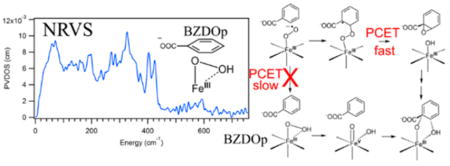
The Rieske dioxygenases are a major subclass of mononuclear nonheme iron enzymes that play an important role in bioremediation. Recently, a high-spin FeIII–(hydro)-peroxy intermediate (BZDOp) has been trapped in the peroxide shunt reaction of benzoate 1,2-dioxygenase. Defining the structure of this intermediate is essential to understanding the reactivity of these enzymes. Nuclear resonance vibrational spectroscopy (NRVS) is a recently developed synchrotron technique that is ideal for obtaining vibrational, and thus structural, information on Fe sites, as it gives complete information on all vibrational normal modes containing Fe displacement. In this study, we present NRVS data on BZDOp and assign its structure using these data coupled to experimentally calibrated density functional theory calculations. From this NRVS structure, we define the mechanism for the peroxide shunt reaction. The relevance of the peroxide shunt to the native FeII/O2 reaction is evaluated. For the native FeII/O2 reaction, an FeIII–superoxo intermediate is found to react directly with substrate. This process, while uphill thermodynamically, is found to be driven by the highly favorable thermodynamics of proton-coupled electron transfer with an electron provided by the Rieske [2Fe-2S] center at a later step in the reaction. These results offer important insight into the relative reactivities of FeIII–superoxo and FeIII–hydroperoxo species in nonheme Fe biochemistry.
Graphical Abstract
1. INTRODUCTION
Mononuclear nonheme iron (NHFe) enzymes are abundant in nature and catalyze a variety of reactions of O2 with organic substrates.1–3 The majority of these enzymes use an FeII site ligated by a facial triad of two His residues and one Glu/Asp carboxylate residue, which remain 6-coordinate (6C) until the substrate and any necessary cofactors are present in the active site.2,4,5 When these are all present, the active site becomes 5- coordinate (5C) through loss of a water ligand, allowing O2 to bind to the FeII site and become activated for reactivity.3 These NHFeII enzymes are divided into subclasses based on the source of the electrons used for the multielectron reduction of O2, the nature of the substrate, and whether a cofactor is required.2 There has been much interest in characterizing the activated O2 intermediates responsible for reacting with substrate. The most well-defined O2 intermediates are S = 2 FeIV=O intermediates,6 which have been trapped in the pter-independent hydroxylases7 and the α-ketoglutarate-dependent enzymes.8 A low-spin FeIII–OOH intermediate that performs H atom abstraction (HAA) has been trapped in the anticancer glycopeptide drug bleomycin,9 and high-spin FeIII–hydroperoxy model complexes have also been shown to exhibit electrophilic reactivities including HAA and sulfoxidation.10,11 An FeIII–superoxo species has been proposed as the reactive intermediate in isopenicillin N-synthase (IPNS).12 The one-electron reduction of O2 to O2•− is unfavorable (−0.16 V),13 but in this enzyme, the thiolate substrate binds directly to the Fe, thereby lowering its FeII/FeIII reduction potential and making the formation of an FeIII–superoxide favorable.14 Indeed, recent experimental data coupled to calculations suggest that an FeIII–superoxo intermediate forms in the reaction IPNS with deuterated variants of its native substrate.15 An S = 2 FeIII–superoxo intermediate has also been trapped in an active site variant of the extradiol dioxygenase homoprotocatechuate 2,3-dioxygenase (HPCD) with a slow substrate; however, in native HPCD, no FeIII is observed during single turnover reactions, so it remains controversial whether a transient FeIII–superoxo is the catalytically relevant intermediate. 16,17
Another important subclass of NHFeII enzymes that is the focus of the present study is the Rieske oxygenases. In these enzymes, a high-spin FeIII–peroxy level intermediate has been trapped in a peroxide shunt reaction,18 while recent single turnover kinetics data potentially implicate an FeIII–superoxo as an active intermediate in the native O2 reaction.19 The Rieske oxygenases catalyze a range of diverse chemistries20 including monooxygenation,21 sulfoxidation,21 and desaturation. 22 Most of the well-studied Rieske oxygenases are dioxygenases (RDOs) that catalyze the cis-dihydroxylation of aromatic rings23 and are important in bioremediation.24,25 In contrast to the NHFeII enzymes described above, the RDOs require an external source of electrons to activate O2. As a result, a reductase and sometimes ferredoxin (fd) protein components are required in addition to the oxygenase component. The catalytically active oxygenase component26,27 consists of an (αβ)3 or α3 trimer, where each α subunit has a mononuclear NHFeII site and a [2Fe-2S] Rieske center.28 The head-to-tail quaternary structure places the NHFeII site of one subunit adjacent to the Rieske center of another subunit, and this combination forms the reactive unit. The Rieske center can exist in either an oxidized, S = 0 FeIII/FeIII form or a reduced, S = 1/2 FeII/FeIII form. O2 activation and reaction with substrate occur at the catalytic mononuclear NHFeII site, and the Rieske center in a neighboring α subunit provides one electron to the NHFeII site during the reaction through a hydrogen bond from a carboxylate residue at the interface of the two subunits.29 At the end of a single turnover cycle, both metal centers are oxidized, indicating that 2 electrons are required for the oxygen activation reaction.30 In order to start the next reaction cycle, the reductase/fd must provide two electrons to reduce the RDO metal centers. From magnetic circular dichroism (MCD) measurements on the RDO naphthalene dioxygenase (NDO), it is known that the NHFeII site becomes 5C only when substrate is present. This opening of a coordination site on the iron in combination with structural changes occurring upon reduction of the Rieske center prime the site for O2 reactivity.31,32 Crystal structures for many members of the RDO family have been solved,27,28,33–37 including some with substrates bound,37–40 which show that substrate does not coordinate to the FeII but binds in its vicinity in a hydrophobic pocket. Two O2-bound crystal structures have been solved, one in NDO with the alternative substrate indole bound37 and the other in carbazole 1,9a-dioxygenase (CARDO) with carbazole bound.39 Both structures show the NHFeII facial triad with one of the carboxylate side chains bound bidentate and the O2 bound side-on. In the case of the CARDO, single-crystal optical spectra showed that the Rieske center is oxidized in this complex. The structural studies were complemented by the single turnover studies described above and by peroxide shunt experiments showing that hydrogen peroxide can provide both the oxygen and the two electrons required for turnover.26,30 Together, these observations led to the proposal that the active intermediate in the RDOs is an FeIII–peroxy or FeIII–hydroperoxy species, where O2 has been reduced by two electrons, one from the NHFeII site and one from the Rieske center.41 The four-electron reduced O2 intermediate, an FeV(O)(OH) species, has also been considered.30
As mentioned above, a solution-phase oxygen intermediate has been trapped in the RDO benzoate 1,2-dioxygenase (BZDO) using the peroxide shunt reaction, where H2O2 is reacted with an FeIII catalytic site and an oxidized Rieske center with the substrate, benzoate, already bound.18 This intermediate, BZDOp, forms the correct cis-dihydroxylated product, 1-carboxy-1,2-cis-dihydroxycyclohexa-3,5-diene (benzoate-cis-diol), but at a much slower rate than in the native O2 reaction with the NHFeII site18,19 (5.8 × 10⁻⁴ s−1 vs 190 s−1, both pseudo first order single-turnover rates). This intermediate has been tentatively assigned as a high-spin FeIII–peroxy species on the basis of Mössbauer spectroscopy, with the binding mode of O2, how this relates to the crystallographic intermediates, and protonation state of the O2 unknown.18 The slow reactivity of BZDOp raises the question of whether it is relevant to the native O2 reaction. Further, recent single-turnover kinetics on the native O2 reaction in BZDO indicate that the O2-bound NHFeII site reacts with the substrate prior to Rieske center oxidation, which implicates an FeIII–superoxy as the reactive intermediate, rather than an FeIII–(hydro)peroxy.19 If an FeIII–superoxy is the active intermediate, this raises the question of what drives its formation, as substrate is not coordinated to the Fe, and from reference 42, O2 binding to an FeII in a facial triad (without substrate bound) is highly endergonic. Accordingly, O2 binding in the absence of substrate is not kinetically relevant for either NDO or BZDO based on the single turnover studies.19,30
To address these issues, it is first necessary to define the structure of BZDOp and determine how this relates to the native reaction of active site FeII with O2. Vibrational spectroscopy is ideal for defining the binding mode and protonation state of the O2. Resonance Raman (rR) would be the traditional method for obtaining vibrational data on the NHFeII active site; however, due to the chromophoric nature of the Rieske center,43 it is not possible to obtain resonance Raman data on the NHFeII site.44 We thus turned to nuclear resonance vibrational spectroscopy (NRVS) to obtain vibrational data on BZDOp. NRVS is a third-generation synchrotron technique where inelastic vibrational sidebands of the 14.4 keV 57Fe Mössbauer transition are observed.45,46 NRVS has the useful property that all normal modes of vibration with 57Fe displacement show intensity, and that intensity is proportional to the amount of Fe displacement in the mode. NRVS thus gives selective vibrational and, therefore, structural information on the Fe active site. For enzyme intermediates with unknown structures, density functional theory (DFT) simulations, where the functional and basis set have been calibrated on well-defined model systems, are used to assign the NRVS spectrum and define the structure. This methodology has previously been applied to the low-spin FeIII hydroperoxy intermediate in bleomycin (BLM),47 the FeIV-oxo intermediate in SyrB248 and the bridged peroxide intermediate P′ in the binuclear Fe site of AurF.49 To calibrate our DFT method for BZDOp and define the binding mode and protonation state of high-spin FeIII–(hydro)peroxy models, we previously analyzed NRVS data on a side-on FeIII–peroxy model10 and an end-on FeIII–hydroperoxy model10 (both high-spin and ligated by the 4-coordinate 1,4,8,11-tetramethyl-1,4,8,11-tetraazacyclotetradecane (TMC) ligand).50
In the present study, we first present the NRVS data of BZDOp and assign its structure based on DFT calculations calibrated to the high-spin FeIII(hydro)peroxy models. We then define its reactivity with substrate, including consideration of whether BZDOp can be in an equilibrium with an FeIII–superoxo reduced Rieske species. We then evaluate the native O2 reaction in BZDO using DFT, including the timing of the electron transfer (ET) from the Rieske center, and based on these experimentally calibrated calculations offer thoughts on how an FeIII–superoxo can be activated for reactivity in the RDOs and how the reactivity of this species compares with that of an FeIII–hydroperoxy intermediate.
2. METHODS
2.1. Preparation of 57Fe BZDOp Samples
57Fe enriched BZDO was heterologously overexpressed, purified, and characterized as previously reported, only changing the growth and overexpression media to a modified Hutner’s mineral base.19,51 The recipe for the defined media was followed as reported except iron was omitted from all media components and 3 mg/L (~60 μM) 57Fe was added to each flask of growth media. Filter sterilized glucose (0.4% w/v) was used as the carbon source and was added from a 20% (w/v) stock. The concentrated 57Fe stock was made by dissolving an isotopically enriched iron powder (Cambridge Isotope Laboratories, ≥ 96% 57Fe) in 4 M HCl overnight. This procedure resulted in 57Fe being ~97% of the total iron present in the Rieske center and the mononuclear Fe as assayed by ICP-MS.
NRVS samples were prepared at 23 °C by concentrating 57Fe-enriched as-purified BZDO to 5 mM. KCN and benzoate were added to the BZDO solution to respective final concentrations of 20 and 50 mM from high concentration stocks to minimize dilution. KCN suppresses background catalase activity preventing degradation of the hydrogen peroxide added during the peroxide shunt.18 KCN was found not to alter the kinetic or spectroscopic features of BZDO. Each NRVS sample was made by mixing 4 parts of the above enzyme solution with 1 part of reaction buffer (50 mM MOPS buffer pH 6.8, 100 mM NaCl) supplemented as described below. BZDOOX samples were prepared by counter mixing with reaction buffer containing 50 mM benzoate. 16O BZDOP samples were prepared by counter mixing with reaction buffer containing 50 mM benzoate and 250 mM H2O2. 18O BZDOP samples were prepared by counter mixing with reaction buffer containing 50 mM benzoate and 250 mM H2 18O2 (Cambridge Isotope Laboratories, 2–2.5% in water, ≥90% H2 18O2). The mixed reactions were then injected into NRVS cells wrapped in Kapton tape and frozen on a liquid nitrogen cooled aluminum block. BZDOP samples were frozen 5 min after addition of the H2O2-containing buffer. ApoBZDO (without mononuclear iron but with full complement of Rieske center) was prepared by overnight dialysis at 4 °C in reaction buffer containing 10 mM EDTA. EDTA was removed by an additional dialysis at 4 °C in reaction buffer. A PD-10 desalting column (GE Healthcare) equilibrated in reaction buffer was used as a final step to remove residual EDTA. ApoBZDO NRVS samples were made with reaction buffer containing 50 mM benzoate.
2.2. NRVS Data Collection and Processing
57Fe NRVS data were collected on BZDO samples at beamline 3-ID-D at the Advanced Photon Source and at BL09XU at SPring-8. The NRVS energy scale was calibrated using [FeIII(Cl4)][NEt4].52 Sample temperatures were maintained at ~60K in copper sample holders mounted in LHe cryostats. Scans of 1 h in measuring time were collected and added together using the PHOENIX software package53 until good signal-to-noise was obtained, and PHOENIX was also used to subtract the elastic peak and generate the final vibrational density of states spectra. To obtain data on the νFe–O in 16O/18O BZDOp, the counting rate in the region from 460–540 cm–1 was increased 10-fold, with the counting rate in the rest of the spectrum (except in an 80 cm−1 range around the elastic peak) decreased to maintain the same measuring time per spectrum. All data, including the isotope-sensitive feature, were reproduced on two replicates of each sample.
2.3. DFT Calculations and NRVS Simulations
DFT calculations were performed using the Gaussian 09 software package, revision D.01.54 The B3LYP functional55–58 and a basis set consisting of 6–311g* on the Fe and 6–311g on all other atoms59–63 was used for all calculations, as this basis set and functional combination has previously been found to perform well in calculating NRVS spectra and reactivities of high-spin FeIII–peroxy species.50,64 Implicit solvation was included in all calculations using the Polarizable Continuum Model (PCM)65 as implemented in Gaussian 09 with ε = 4.0. No crystal structure exists for the oxygenase component of BZDO, but BZDO and NBDO have high sequence similarity (45%) and identity (29%),66 so the crystal structure of nitrobenzene dioxygenase (NBDO) with substrate bound was used as the starting point for the calculations (PDB code 2BMQ).38 Nitrobenzene was modeled as benzoate (protonated to eliminate self-interaction effects), and amino acid residues were truncated to the α-carbons. O2 was added to these structures computationally to generate the NRVS structural models for BZDOp and the initial FeIII–superoxo intermediate in the native reaction coordinate. Bond constraints for calculating a 2D potential energy surface were included using the modredundant keyword in Gaussian 09. For simulating the NRVS spectra, DFT frequency calculations were initially calculated using natural abundance masses, after which the terminal hydrogen atoms on the truncated α-carbons were increased to 100 amu and frequencies were recalculated to remove spurious vibrations associated with the truncation scheme.67 NRVS spectra were simulated from these heavy mass frequency calculations using the gennrvs script.68 Molecular orbital contours were generating using LUMO,69 and Mulliken orbital populations were calculated using QMForge.70
3. RESULTS AND ANALYSIS
3.1. NRVS Definition of BZDOp
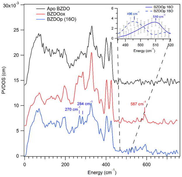
NRVS data were collected on four BZDO samples, all of which had 57Fe loaded into the Rieske center: apo BZDO, where the catalytic site was not loaded with Fe but the oxidized Rieske center is present, ferric resting BZDO (BZDOOX), which is the starting material of the BZDOp formation reaction and has the Rieske center oxidized and 57Fe loaded and oxidized in the catalytic site, and 16O- and 18O-labeled BZDOp, where the peroxy intermediate made up 60% of the catalytic site 57Fe (with 30% due to BZDOOX and 10% due to product complex from EPR, see Figure S1). These data are shown in Figure 1.
Figure 1.
NRVS spectra of BZDO. The Rieske center is loaded with 57Fe in all spectra. Black: NRVS of the Rieske center (apo BZDO, catalytic site not loaded with 57Fe). Red: BZDOOX (catalytic site loaded with 57Fe). Blue: BZDOp generated with H2 16O2 (catalytic site loaded with 57Fe). Inset: NRVS of BZDOp generated with H2 16O2 (blue solid line) and H2 18O2 (blue dashed line) in the region between 485 and 520 cm−1 showing a low-intensity isotope-sensitive feature. These data were collected with a 10× longer measurement time between 460 and 540 cm−1 than the spectrum shown in blue at the bottom of this figure (see the Methods). Error bars (gray) are calculated based on the number of counts in the raw spectrum and were propagated upon baseline subtraction (see Figure S2 for the PVDOS spectra for 16O and 18O BZDOp between 460 and 540 cm−1).
From the NRVS data, there are two major spectral features in BZDOp that are distinct from the Rieske and BZDOOX features. One is the pair of peaks at 270 and 284 cm−1 (blue spectrum), and the other is a peak at 510 cm−1 that shifts to 496 cm−1 with 18O substitution (Figure 1, inset. Note that the data in the inset are in the 485–520 cm−1 range taken with additional scans at 10× the measurement time relative to the blue spectrum to improve the S/N; see Figure S2). (The peak at 587 cm−1 is not isotope sensitive and appears at the same energy in BZDOOX.) Due to its isotope sensitivity, the 510 cm−1 feature can be assigned as the νFe–O. Qualitatively, based on a previous NRVS study on high-spin FeIII–(hydro)peroxy models,50 the peaks centered at 277 cm−1 are equatorial Fe–NHis stretches. This previous study showed that the energy of the νFe–O and the splitting between equatorial Fe–N stretches are sensitive to the coordination mode of O2 and its protonation state. From the model study, the side-on FeIII–peroxo has a symmetric νFe–O of 430 cm−1 and an equatorial Fe–N splitting of 23 cm−1, while for a hypothetical in silico side-on FeIII–hydroperoxo these are 521 and 14 cm−1, respectively, and for the end-on FeIII–hydroperoxo these are 619 and 25 cm−1. Both the νFe–O of 510 cm−1 and the 14 cm−1 splitting between the Fe–N peaks are consistent with BZDOp being a side-on FeIII–hydroperoxy.
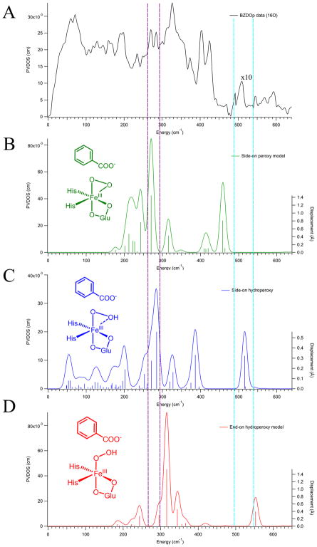
DFT calculations were used to make a rigorous assignment of the structure of BZDOp via the NRVS spectrum. Three primary candidate structures for BZDOp were considered: sideon FeIII–peroxy, side-on FeIII–hydroperoxy, and end-on FeIII–hydroperoxy shown in Figure 2. Attempts to optimize an end-on unprotonated FeIII–peroxy structure resulted in an end-on FeII-superoxy electronic structure inconsistent with the Mössbauer data.18 The cluster model used for these calculations (derived from NBDO as described in section 2.3) included all first-sphere residues and two conserved second-sphere Asn residues, Asn258 and Asn199 (labeled using the NBDO residue numbers), which are involved in hydrogen bonding to the substrate and to the O2, respectively. DFT simulations derived from the three possible structures (in insets, with final DFT structures given in Figure S3) are shown in Figure 2.
Figure 2.
NRVS spectrum of BZDOp (A) compared with three DFT-simulated spectra of possible structures: side-on peroxy (B, green), side-on hydroperoxy (C, blue), and end-on hydroperoxy (D, red). Intensity in the region between 480 and 540 cm−1 (between the cyan lines) has been multiplied by 10 in the BZDOp (A) data to show the Fe–O stretch on the same scale as the rest of the NRVS spectrum. The intensities in the simulations have not been adjusted. The right axis of the simulations depicts the calculated amount of Fe displacement in each normal mode, represented by the vertical sticks, in Å. Regions where BZDOp has features distinct from the Rieske center, and BZDOOX are highlighted between purple and cyan vertical dotted lines. Schematic depictions of the DFT structures are included as insets.
As shown in Figure 2, only the side-on hydroperoxy model (Figure 2 C) is consistent with the NRVS data of BZDOp (Figure 2 A), as this model predicts an νFe–O at 516 cm−1 (510 cm−1 in the data) and a pair of intense Fe-His stretches at 285 and 271 cm−1. These are inequivalent due to the differing Fe–NHis bond lengths of 2.07 and 2.08 Å, respectively, and consistent with the observed 284 and 270 cm−1 peaks in the NRVS data. In the side-on peroxy structure, a symmetric νFe–O2 is calculated at 458 cm−1, and the intense νFe–NHis appear at 270 and 243 cm−1, which are all too low in energy to be consistent with the NRVS data, and the 27 cm−1 splitting between the νFe–NHis is also too large. For the end-on hydroperoxy model (which is 1 kcal/mol higher in free energy than the side-on hydroperoxy), the νFe–O is at 553 cm−1 and the νFe–NHis are at 316 and 296 cm−1, all too high in energy relative to the NRVS data, with the 20 cm−1 splitting between the νFe–NHis again too large relative to the data (though it should be noted that this splitting is within the 8 cm−1 resolution of the experimental value). From the DFT modeling, BZDOp can thus be assigned as a side-on FeIII–hydroperoxy, consistent with the qualitative prediction presented above based on model complexes. The DFT structure of BZDOp is shown in Figure 3, and relevant calculated structural and vibrational parameters for this model, as well as the side-on peroxy and end-on hydroperoxy, are given in Tables S1 and S2.
Figure 3.
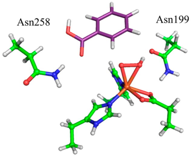
DFT-optimized structure of BZDOp that is consistent with the NRVS data. Protein carbons are shown in green, benzoate carbons in purple, nitrogens in blue, oxygens in red, hydrogens in white, and iron in orange.
3.2. Reaction Coordinate of BZDOp
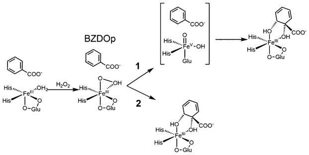
With the structure of BZDOp defined using NRVS spectroscopy, its cis-dihydroxylation reactivity was computationally investigated. Two primary reaction pathways for a side-on FeIII–hydroperoxy have been proposed in the literature: (1) initial heterolytic cleavage of the O–O bond to form an FeV(O)(OH) that then reacts with substrate41,71 and (2) direct attack of the unprotonated O on the substrate concerted with O–O cleavage,72 as shown in Scheme 1.
Scheme 1. Two Possible Reaction Mechanisms for BZDOp Involving an O–O Cleavage Prior to Reaction with Substrate (1) or Direct Attack on the Substrate Concerted with O–O Cleavage (2)a.
aThe Rieske center remains oxidized throughout and does not participate in the shunt reaction.
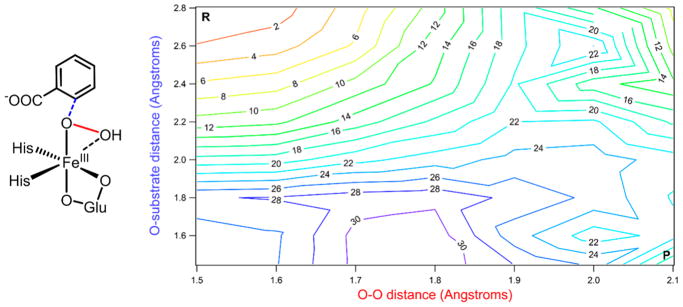
Previous computational studies disagree about which of these mechanisms is more feasible.71–73 To evaluate this reaction coordinate, the NRVS structure of BZDOp was used as a starting point to generate a 2D potential energy surface (PES), where the two coordinates are O–O distance and non-protonated O–substrate (C2) distance, as depicted in Figure 4, left. The results of these calculations are displayed in Figure 4, right.
Figure 4.
Left: Schematic of BZDOp with the O-substrate (carbon 2) coordinate shown in blue and the O–O coordinate shown in red. Right: 2D potential energy surface for BZDOp reacting with substrate, with O–O elongation on the x-axis and O-substrate contraction on the y-axis. The starting point of the surface is at the upper-left corner marked by an R, and the ending point is at the lower-right and marked by a P. Electronic energies are given on the contours in 2 kcal/mol increments, with colors closer to the blue end of the spectrum corresponding to higher energies.
From the PES shown in Figure 4, decreasing the O–substrate distance without increasing the O–O distance is energetically unfavorable and would go through a barrier of ~27 kcal/mol, while cleaving the O–O bond would go through a barrier of ~19 kcal/mol. No transition state for direct attack could be located. This can be rationalized by considering the frontier molecular orbital (FMO) of BZDOp that would participate in the direct electrophilic attack, which is its LUMO, a hydroperoxo σ* orbital oriented along the O–O vector (Figure S4). Due to the positioning of Asn258 (Figure 3), the substrate is unable to orient itself along this O–O vector, and the O–O bond must cleave before attack on the substrate. A recent QM/MM study71 similarly found that steric effects arising from residues in the binding pocket of NBDO prevent the substrate from adopting the position necessary for a concerted TS.
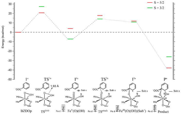
The O–O cleavage mechanism was evaluated on the S = 5/2 and S = 3/2 surfaces. The results of these calculations are shown in Figure 5 and summarized in Table 1.
Figure 5.
Calculated mechanism of cis-dihydroxylation by BZDOp. All energies given are Gibbs free energy. The reaction was calculated on the S = 5/2 surface (red lines) and S = 3/2 surface (green lines). Schematics of the structures along the reaction coordinate are given and labeled at the bottom, with the DFT structures shown in Figure S5 and FMOs given in Figure S6. The electronic structure schemes for the Fe d orbitals, the substrate π orbital involved in the reaction, and the OH group are given at the bottom for the final four structures corresponding to the lowest energy spin state.
Table 1.
Energies, Bond Lengths, and Spin Densities for Structures along the BZDOp cis-Dihydroxylation Reaction Coordinatea
| species | ΔE | ΔH | ΔG | O–O bond | Fe–Oprox bond | Fe–O(H) bond | Fe spin | substrate spin | Oprox spin | OH spin |
|---|---|---|---|---|---|---|---|---|---|---|
| BZDOp (1a) | 0.0 | 0.0 | 0.0 | 1.53 | 1.91 | 2.19 | 4.17 | 0.01 | 0.33 | 0.10 |
| TS1a (5/2) | 20.2 | 17.2 | 21.8 | 1.93 | 1.81 | 1.91 | 3.93 | −0.04 | 0.34 | 0.39 |
| TS1a (3/2)b | 26.2 | 24.9 | 28.6 | 1.93 | 1.81 | 1.91 | 1.74 | 0.00 | 0.89 | 0.47 |
| I1a (5/2) | 5.2 | 4.4 | 5.5 | 2.30 | 1.73 | 1.78 | 3.23 | 0.01 | 0.97 | 0.58 |
| I1a (3/2) | −4.6 | −3.1 | −4.7 | 2.57 | 1.64 | 1.75 | 1.96 | 0.02 | 0.85 | 0.22 |
| TS2a (5/2) | 15.9 | 13.9 | 16.5 | 2.60 | 1.80 | 1.77 | 3.47 | 0.63 | 0.50 | 0.15 |
| TS2a (3/2) | 13.4 | 12.1c | 13.2c | 2.67 | 1.75 | 1.76 | 3.33 | −0.60 | −0.06 | 0.15 |
| I2a (5/2) | 11.5 | 14.7c | 12.8c | 2.65 | 1.91 | 1.78 | 4.05 | 0.32 | 0.12 | 0.21 |
| I2a (3/2) | 10.5 | 7.4 | 10.8 | 2.68 | 1.87 | 1.77 | 2.97 | −0.23 | 0.05 | 0.10 |
| Pa (5/2) | −41.1 | −39.7 | −37.2 | 2.50 | 1.82 | 1.92 | 4.25 | 0.03 | 0.25 | 0.05 |
| Pa (3/2) | −25.3 | −25.0 | −19.6 | 2.49 | 1.82 | 1.92 | 2.82 | −0.01 | 0.06 | 0.01 |
Energies are given in kcal/mol and bond lengths in Å.
A TS for O–O cleavage could not be optimized on the S = 3/2 surface; these parameters come from an S = 3/2 single point energy and frequency calculation on the optimized S = 5/2 TS1a.
These values were obtained from a single-point frequency calculation on the nonoptimized IRC products of TS2a.
BZDOp is a high-spin (S = 5/2) FeIII species.18 The initial step in the reaction is cleavage of the peroxy O–O bond, which goes through a barrier of 21.8 kcal/mol on the S = 5/2 surface (TS1a). On the S = 5/2 surface, this process is best described as a homolytic cleavage where one alpha electron from the Fe and one beta electron from the protonated O (OH) are used to cleave the O–O σ bond, as evidenced by the buildup of spin density on OH at TS1a (Table 1). This process generates an FeIV(O)(•+OH) product, where the S = 2 FeIV and the S = 1/2 •+OH are ferromagnetically coupled. However, the S = 3/2 cleavage product is much lower in energy (−4.6 kcal/mol relative to BZDOp, versus +5.2 kcal/mol for S = 5/2), so there is a spin crossover from the S = 5/2 to the S = 3/2 surface along the O–O cleavage coordinate. The S = 3/2 product is an FeV(O)(OH) species, where there are three α electrons in the Fe d orbitals and the O–O bond has been heterolytically cleaved by two electrons from the Fe, as shown at the bottom of Figure 5. (The S = 1/2 cleavage product was also considered. This is a low-spin FeV(O)(OH) with an energy of 5.2 kcal/mol, higher in energy than the S = 3/2 product. The S = 3/2 FeV being lower in energy here is consistent with computational predictions that an FeV(O) with a cis OH group would have its high-spin configuration lowest in energy.74) This FeV(O)(OH) intermediate is shown as I1a in Figure 5 and Table 1, and the DFT structure is given in Figure S5. The next step in the reaction involves attack on the substrate by the oxo group, as the OH group is not oriented well for attack on the substrate (see Figure S5, upper right). On the S = 3/2 surface, the oxo group attacks C1 of the substrate with a barrier of 13.2 kcal/mol relative to BZDOp, much lower than the barrier for O–O cleavage. At the transition state, TS2a (from the spin densities in Table 1 and the FMOs in Figure S6), one α electron from the substrate π HOMO has been transferred to the Fe, as shown schematically in Figure 5, bottom. The intrinsic reaction coordinate (IRC) product of this transition state, I2a, is best described as an FeIII–O-benzoate+ bridged species, where the second substrate π HOMO electron has been mostly transferred to the Fe (though there is still a small amount of FeIV benzoate• character, as evidenced by the spin densities in Table 1 and FMOs in Figure S6). This species does not correspond to a local energy minimum, and upon geometry optimization, I2a goes directly to the final product Pa, where the OH group on the Fe has transferred to the substrate and there has been a spin crossover back to the S = 5/2 surface to generate an S = 5/2 FeIII product bound complex at −37.2 kcal/mol. From these calculations, the rate limiting step of the BZDOp reaction with substrate is O–O cleavage with a barrier of 21.8 kcal/mol, which is consistent with the experimental slow rate of product formation in the peroxide shunt reaction (5.8 × 10⁻⁴ s−1).18 Note that the slow rate of product formation could also be due to slow peroxide binding; however, there is an immediate shift in the EPR signal of BZDOOX upon addition of H2O2,18 and its binding is thus likely not rate limiting.
Since literature results indicate that an end-on high-spin FeIII hydroperoxide should be capable of electrophilic reactivity, 10,11,64 the possibility that BZDOp can isomerize to end-on hydroperoxide to electrophilically attack the substrate through its protonated O was also evaluated. The end-on hydroperoxo is only 1 kcal/mol higher in free energy than the side-on structure and can attack benzoate at C1, but with a barrier of 30.1 kcal/mol, to form an FeIV(O) and (benzoate•)-(OH) at 22.4 kcal/mol. Interestingly, this barrier is much higher than the 18.8 kcal/mol barrier found for a high-spin end-on FeIII–hydroperoxy-TMC model complex performing H atom abstraction from xanthene.64 This can be attributed to the thermodynamics of the products: if the thermodynamics of the products are removed from the barrier to obtain an approximate estimate of the intrinsic ΔG‡,75,76 the barriers become closer (19.0 kcal/mol for BZDOp, 23.4 kcal/mol for the TMC hydroperoxo model). The high barrier for end-on hydroperoxo attack on benzoate rules out this mechanism for the peroxide shunt reaction relative to the heterolytic O–O cleavage mechanism presented in Figure 5.
3.3. Thermodynamic Correlation of BZDOp with a FeIII–O2•− Rieskered Species
The barrier of 21.8 kcal/mol for cis-dihydroxylation via O–O heterolysis of the hydroperoxo in BZDOp determined above is consistent with the observed slow rate in the peroxide shunt reaction. However, there also exists the possibility that BZDOp could be in an equilibrium with a FeIII–O2 •− Rieskered species (generated by deprotonation and electron transfer back to the Rieske center), which could itself be the reactive intermediate and has recently been invoked as a potential intermediate in the native O2 reaction of BZDO (vide infra).19 To investigate this possibility, the thermodynamics of reducing the Rieske center by one electron and deprotonating and oxidizing BZDOp by one electron were calculated, as shown in Scheme 2.
Scheme 2. Thermodynamics of Conversion between BZDOp (Left) and an S = 2 FeIII–O2 •− Rieskered Species (Right)a.
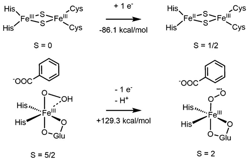
aThe numbers given reflect bulk solvent as the proton acceptor. The net reaction favors BZDOp by 43.2 kcal/mol.
Reducing the Rieskeox site by one electron is worth −86.1 kcal/mol. Converting this to a potential relative to the SHE77 gives a value of −0.54 V. This is more negative than the measured value for naphthalene dioxygenase (−0.15 V), but the 0.39 V (9 kcal/mol) discrepancy is typical of calculations on Rieske centers.78 For BZDOp, conversion to a superoxo species necessitates deprotonation, and it is important to consider the proton acceptor. One potential proton acceptor is bulk solvent, which has a proton solvation free energy of −265 kcal/mol.79 For BZDO, the other reasonable proton source is Arg312, which is 7.9 Å away from the active site in the crystal structure of NBDO and conserved in BZDO.38 The Gibbs free energy of protonating the guanidine group of Arg312 is −275 kcal/mol, 10 kcal/mol more favorable than bulk solvent.80 It was found that deprotonating BZDOp and oxidizing it by one electron to an S = 2 FeIII–O2 •− species (the lowest energy superoxo, vide infra) is unfavorable by 129.3 kcal/mol if the proton goes to solvent, or 119.3 kcal/mol if the proton goes to the guanidine group. The net thermodynamics of converting BZDOp to a superoxo Rieskered species are thus +43.2 kcal/mol (H + from solvent) or +33.2 kcal/mol (H+ from Arg+). If the experimental reduction potential of the Rieske center in NDO ferredoxin (−95.2 kcal/mol81) is used instead of the calculated value, the thermodynamics become +24.1 kcal/mol with H+ from Arg+. Even this lowest value is too large to enable any equilibrium between BZDOp and a superoxo species. Thus, the side-on hydroperoxy–heterolytic cleavage mechanism presented in section 3.2 describes the peroxide shunt reaction in the Rieske dioxygenases but, as shown below, is not relevant to the O2 reaction of the reduced enzyme.
3.4. Reaction Coordinate of FeII BZDO with O2
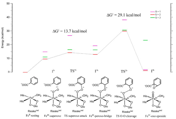
With the peroxide shunt mechanism in the Rieske dioxygenases evaluated based on the structure of BZDOp elucidated by NRVS, it is now important to consider the native FeII/O2/reduced Rieske center/benzoate reaction and understand whether this relates to peroxide shunt reactivity. From single-turnover kinetics measurements of the native reaction of BZDO and O2 with benzoate and several fluorinated derivatives,19 it was determined that the pseudo-first-order rate constant of Rieske oxidation (kobs = 190 s−1, ΔG‡ ~13 kcal/mol) is equal to the pseudo first order rate constant of product formation, meaning that the rate-limiting step either occurs before or is concerted with the electron transfer from the Rieske center. Further, the rate constant of Rieske oxidation was dependent on substrate type. This mechanism would involve an initial FeIII–superoxo intermediate that attacks the substrate before accepting an electron from the Rieske center. To evaluate this hypothesis, a reaction coordinate for BZDO with O2 and a reduced Rieske center was evaluated, as shown in Figure 6 and summarized in Table 2.
Figure 6.
Reaction coordinate for BZDO with O2 without transferring an electron from the Rieske center. The displayed energies are Gibbs free energies. Red lines are the S = 2 surface, green are S = 3, and purple are S = 1. Schematics of the structures are shown at the bottom, with the lowest energy DFT structures shown in Figure S7. The rate-limiting step for this reaction, TS2b, corresponds to cleavage of the peroxo O–O bond and has a barrier of 29.1 kcal/mol, too high to be involved in catalysis; therefore, ET must occur prior to this step.
Table 2.
Energies and Relevant Parameters for Structures along the Computational Reaction Coordinate for BZDO with O2a
| ΔE | ΔH | ΔG | O–O bond | Fe spin | Oprox spin | Odist spin | substrate spin | |
|---|---|---|---|---|---|---|---|---|
| 1b (S = 3) | −0.1 | 1.1 | 13.7 | 1.36 | 4.20 | 0.58 | 0.72 | 0.05 |
| 1b (S = 2) | 0.3 | 2.8 | 9.9 | 1.37 | 4.22 | −0.06 | −0.57 | −0.06 |
| 1b (S = 1) | 2.9 | 6.6 | 16.8 | 1.37 | 1.06 | 0.42 | 0.55 | 0.00 |
| TS1b (S = 3) | 4.4 | 8.3 | 16.9 | 1.45 | 4.22 | 0.34 | 0.35 | 0.67 |
| TS1b (S = 2) | 3.9 | 7.8 | 13.7 | 1.47 | 4.21 | 0.24 | −0.23 | −0.65 |
| TS1b (S = 1) | 12.3 | 16.7 | 26.3 | 1.48 | 0.96 | 0.12 | 0.42 | 0.55 |
| I1b (S = 3) | 3.1 | 6.4 | 15.4 | 1.49 | 4.23 | 0.14 | 0.29 | 0.92 |
| I1b (S = 2) | 2.1 | 4.7 | 11.9 | 1.50 | 4.23 | −0.04 | 0.29 | −0.90 |
| I1b (S = 1) | 5.6 | 10.6 | 19.9 | 1.51 | 2.72 | 0.20 | −0.05 | −0.92 |
| TS2b (S = 3) | 18.2 | 21.6 | 30.0 | 2.01 | 4.09 | 0.57 | 0.26 | 0.72 |
| TS2b (S = 2) | 13.8 | 16.0 | 29.1 | 1.93 | 3.90 | 0.05 | 0.17 | −0.44 |
| TS2b (S = 1) | 22.7 | 23.0 | 38.6 | 1.98 | 2.99 | 0.18 | −0.45 | −0.85 |
| I2b (S = 3) | 12.6 | 17.0 | 23.9 | 2.72 | 4.24 | 1.28 | 0.01 | 0.01 |
| I2b (S = 2) | −10.1 | −5.9 | 3.7 | 4.25 | 3.23 | 0.54 | 0.00 | 0.00 |
| I2b (S = 1) | −10.9 | −4.9 | 4.0 | 4.10 | 1.34 | 0.73 | 0.00 | 0.00 |
All energies are relative to the 5C FeII site + 3O2 in kcal/mol, and bond lengths are given in Å.
The first step in the reaction is binding O2 to the FeII, which has gone 5C upon binding substrate.31 This is an S = 2 FeIII–O2 •− species that is uphill in free energy by 9.9 kcal/mol, consistent with previous calculations on naphthalene dioxygenase and on O2 binding to the 5C facial triad in the extradiol dioxygenases.42,82 This species, 1b (Figure 6), is best described as an S = 5/2 FeIII site antiferromagnetically coupled to an S = 1/2 O2− radical, giving the S = 2 lowest energy spin state. The superoxide structure would be 6C with a bidentate carboxylate, two His, and a water ligand (consistent with pulsed EPR data on the {FeNO}7 substrate bound species in NDO).32 The superoxo, 1b, can attack carbon 2 of benzoate with a total barrier of 13.7 kcal/mol (TS1b) on the S = 2 surface, still consistent with the single-turnover rate, to generate an FeIII–peroxobenzoate radical bridged species, I1b, at 11.9 kcal/mol. This process involves electrophilic attack by the superoxo π*v α-LUMO, perpendicular to the Fe–O–O plane, on the substrate π HOMO, as shown in Figure 7, left.
Figure 7.
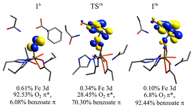
α LUMO FMO of species along the S = 2 superoxo attack on benzoate coordinate, with labels corresponding to Figure 6 at the top and Mulliken populations given at the bottom. The initial attacking superoxo species 1b primarily has a hole in the O2 •− π*v FMO (perpendicular to the O–O plane), and at TS1b this hole character is predominantly shifted to the substrate, generating the FeIII–O2-(benzoate•) intermediate I1b. (Note that these FMOs are taken from calculations where Asn203 has been added to the model, vide infra; this has no significant effect on energetics or orbital populations.).
As the superoxo species attacks benzoate, the radical character shifts from the benzoate π HOMO onto the O2 •−, with the transfer largely complete at the transition state TS1b. This can be seen from the LUMO in Figure 7, middle, which is predominantly benzoate π in character, and from the O–O bond length at the TS (Table 2) of 1.45 Å, significantly lengthened from the 1.37 Å distance of the superoxo reactant. This produces species I1b, which has an FeIII peroxide bridging a benzoate that has been oxidized by one electron. The next step in the reaction would involve homolytic cleavage of the peroxo O–O bond to generate an FeIV-oxo benzoate epoxide species I2b, with the S = 1 and S = 2 FeIV species nearly isoenergetic (Figure 6). While either of these species could plausibly complete the cis-dihydroxylation reaction, the barrier for cleaving the O–O bond (TS2b) is too high; this barrier is 29.1 kcal/mol on the lowest-energy S = 2 surface, relative to the ~13 kcal/mol barrier estimated from the single turnover kinetics. Thus, the Rieske center must provide an electron to drive the reaction at a stage prior to this O–O cleavage step, and this could occur at either the superoxo species 1b or the bridged species I1b in Figure 6. These possibilities are evaluated below.
3.5. Proton-Coupled Electron Transfer to Drive Reactivity
Since the native O2 reaction in BZDO cannot proceed past the FeIII–peroxoaryl radical species I2b without electron transfer from the Rieske center, the kinetics of both an electron transfer (ET) and proton-coupled electron transfer (PCET) to the catalytic site along the reaction coordinate were evaluated at both the peroxo bridged I1b step and the earlier superoxo 1b step. The rate of electron transfer between a donor and acceptor, kET, is given in Marcus theory,83 eq 1.
| (1) |
kET is dependent on HDA, the electronic coupling between the donor and acceptor, ΔG°, the driving force of the reaction, λ, the reorganization energy, and temperature (T). kb is the Boltzmann constant, and ℏ is the reduced Planck’s constant. λ is further divided into inner-sphere (λi) and outer-sphere (λo) components, which reflect the change in the geometry of the ligands and solvent, respectively, upon electron transfer. λo is assumed to be 0.4 eV for both the catalytic Fe and Rieske sites,84 HDA is assumed to be 0.05 cm−1, consistent with previous work,82 ΔG° and λi for the catalytic Fe site were both obtained from DFT calculations85 (see the SI for details on the λi calculation), ΔG° for oxidizing the Rieske center is +95.2 kcal/mol as discussed in section 3.3, and λi for the Rieske center is 0.56 eV as calculated previously.86
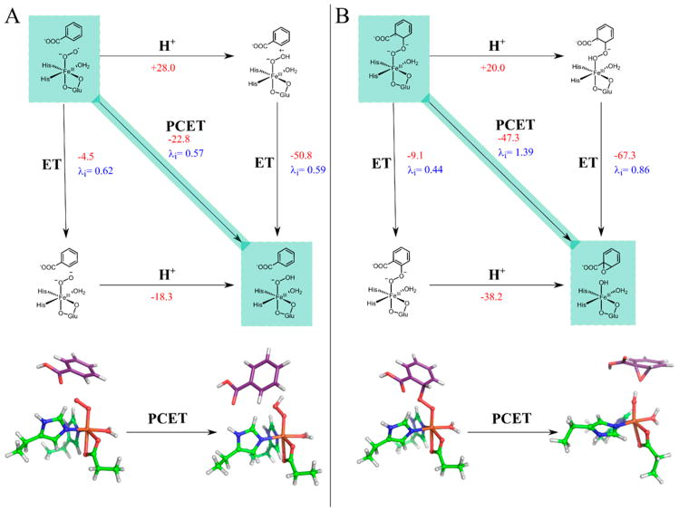
The calculated ΔG° and λi values for PCET, as well as uncoupled ET and proton transfer (PT), to the superoxo species 1b and the peroxo bridged species I1b are shown in parts A and B, respectively, of Figure 8.
Figure 8.
(Top) Diagrams schematically depicting PCET to the superoxo species (A) and the peroxy-bridged species (B), as well as the uncoupled PT → ET and ET → PT processes. The fastest kinetic step (PCET in both cases) is highlighted in green. ΔG° in kcal/mol are shown for all steps in red, with steps involving protonation using guanidinium as the proton source, and λi in eV are given for PCET and ET steps. The bottom of both sides shows the DFT structures for the reactants and products of the PCET process with second-sphere residues hidden for clarity. Substrate carbons are in purple, protein carbons in green, oxygen in red, nitrogen in blue, iron in orange, and hydrogen in white.
For these calculations, Asp203, which bridges between the catalytic and Rieske sites to facilitate ET, was included in the cluster model to neutralize the charge on the site for the uncoupled ET and PT calculations. Both Arg312 (vide supra) and the water coordinated to the Fe were considered as potential proton sources, with the main text focusing on the Arg312 calculations and the coordinated water results, which are similar but give lower rates for both processes as presented in the SI. Note that the solvent cannot be the source of the proton, as the rate of Rieske oxidation in single turnover is pH independent from 6.8 to 8.0 (see the supporting methods, Table S3, and Figure S9 in the SI for details), eliminating PCET to the superoxo as the rate-determining step (vide infra). As shown in Figure 8B, bottom, PCET to the peroxy-bridged species I1b, protonating the oxygen proximal to the Fe, leads to spontaneous heterolytic cleavage of the O–O bond to generate an FeIII–OH benzoate epoxide (I2c). This process is highly favorable, with a ΔG° of –47.3 kcal/mol, though it also has a fairly large λi of 1.39 eV. Adding the λi and the λo for the catalytic and Rieske sites, the total λ for this process is 2.75 eV, and eq 1 gives a kET for this process of 5600 s−1 at 277 K (the temperature at which single turnover kinetics were measured19). This PCET process is thus driven by the highly favorable thermodynamics associated with reductive cleavage of the O–O bond, which compensates for the large reorganization energy. The kET of 5600 s−1 is faster than the 190 s−1 rate limiting step of product formation in single turnover,19 making this step catalytically feasible. As shown in the diagram in Figure 8B, top, PT to I1b prior to ET is unfavorable thermodynamically (ΔG = +20.0 kcal/mol), and performing ET prior to PT is slow relative to the coupled PCET process (kET = 9.6 s−1 versus 5600 s−1).
Figure 8A evaluates the alternative of PCET/ET to the FeIII–superoxo S = 2 species 1b to generate an S = 5/2 FeIII–hydroperoxy or peroxy species. The PCET process has a relatively small λi of 0.57 eV (λtotal = 2.03 eV) but is less thermodynamically favorable with ΔG° = −22.8 kcal/mol (consistent with the results in section 3.3). Using eq 1, these parameters give a kET of 31 s−1. This is slow relative to the 190 s−1 rate-limiting step in single turnover, and PCET at this step can be eliminated. To estimate the error in these calculated kET, we assume an error in λ of ±0.2 eV, an error in ΔG° of ±5 kcal/mol, and an error in HDA of ±0.03 cm−1. These give a wide range of possible rates (22.8–2.4 × 10⁵ s−1 for the kET to the peroxo and (1.9 × 10⁻²) – (9.2 × 10³) s−1 for kET to the superoxo). However, the calculated PCET rate to the superoxo is always at least 2 orders of magnitude slower than that to the peroxo bridge, as any errors in the calculated values would trend in the same direction. Uncoupling the ET and PT at the FeIII–superoxide step further slows this process, with kET = 0.045 s−1 calculated for ET from the values shown in Figure 8A, and PT prior to ET is also disfavored due to highly unfavorable thermodynamics (+28.0 kcal/mol). The slow calculated rate of PCET to the superoxo species and the fast calculated rate of PCET to the peroxy bridged species indicate that the native O2 reaction proceeds through an initial S = 2 FeIII–superoxo intermediate (1b) that attacks benzoate with a total barrier of 13.7 kcal/mol (Figure 6) that is consistent with the experimental rate-limiting step (k = 190 s−1). This generates an S = 2 FeIII–peroxobenzoate radical bridged species (I1b), which accepts an electron from the Rieske center and a proton from guanidinium (or another proton source) to generate an S = 5/2 FeIII–OH benzoate epoxide species (I2c) with a rate of 5600 s−1. Thus, the reaction up to this point would be rate limited by superoxo attack on benzoate, consistent with the substrate dependence of the rate of Rieske oxidation. It should be noted that using bulk solvent as the proton source accelerates both PCET rates, making PCET to the superoxo competitive with the rate of its attack on the substrate. This is inconsistent with the experimental observations that the rate of Rieske oxidation is pH independent and substrate dependent, eliminating bulk solvent as the proton source for PCET. Importantly, the rate of PCET to the peroxo bridge is always calculated to be 2 orders of magnitude greater than the rate of PCET to the superoxo due to the much more favorable ΔG0 for the former process, independent of any assumptions made about proton source, HDA, and λ. Completion of the native O2 cis-dihydroxylation reaction coordinate is evaluated below.
3.6. Completion of the Native O2 Reaction Coordinate
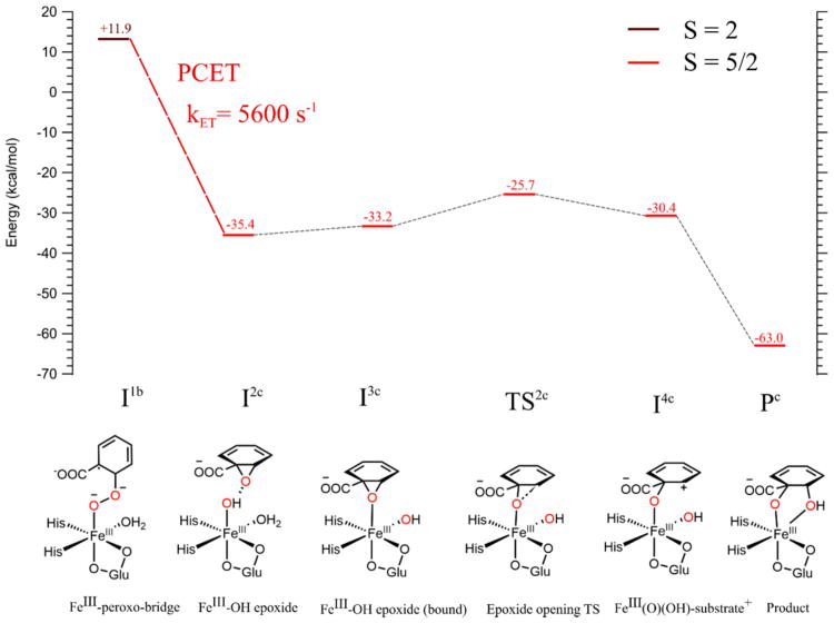
The calculated reaction coordinate for completing cis-dihydroxylation following PCET to I1b is shown in Figure 9.
Figure 9.
Reaction coordinate for completing the native O2 mechanism in BZDO. Oxygen atoms from O2 are shown in red. All energies are in Gibbs free energy relative to the FeII resting starting material (Figure 6), with PCET energetics as in Figure 8. After PCET to the S = 2 peroxy-bridged intermediate (brown line and text), all structures considered were on the S = 5/2 surface (red lines and text). Structural schemes for all species on the reaction coordinate are shown at the bottom, with DFT structures given in the SI (Figure S8). All calculated structures here included Asp303 in the cluster model.
PCET to the peroxy-bridged species I1b generates the FeIII(OH) epoxide species I2c at −35.4 kcal/mol relative to the resting FeII + O2 system. In I2c, the epoxide O is oriented toward the Fe and is hydrogen bonded to the hydroxy H, and thus, it is primed for formation of a cis-diol as rotation of the substrate for formation of a trans-diol would be precluded by the hydrophobic residues lining the substrate cleft.38 We evaluated the possibility of direct attack of the epoxide by the hydroxy. A 1D linear transit calculation found that, while this process would generate the correct cis-dihydroxylated product, it would involve a large barrier of at least ~19 kcal/mol (see Figure S10). We thus investigated the alternative of the epoxide first binding to the Fe. From I2c, binding the epoxide with displacement of the water ligand is uphill by 2.2 kcal/mol (I3c). It is also possible that the solvent water dissociates prior to this step, as this water is labilized by 21.9 kcal/mol in enthalpy (22.7 kcal/mol in free energy) in going from the superoxo species 1b to the peroxo bridge species I1b due to a stronger Fe–O donor bond (1.89 Å in the peroxo vs 1.99 Å in the superoxo). Water dissociation prior to PCET is consistent with the minimal solvent exchange observed in the native O2 reaction of NDO.87 PCET to this peroxo bridged intermediate without a coordinated water occurs at a rate of 1.54 × 10⁴ s−1, generating a 5C FeIII–OH epoxide species similar to I2c; binding of this epoxide to the Fe generates I3c (details on this PCET and subsequent epoxide binding are given in the SI). Note that an ENDOR study32 on NDO found that the substrate moves closer to the Fe (by 0.5 Å) upon oxidation of the Rieske center; this would facilitate binding of the epoxide to the Fe. From the epoxide-bound intermediate, opening of the epoxide occurs with a barrier of 7.5 kcal/mol (TS2c). The IRC for this transition state goes to an FeIII–O–(benzoate+) bridged species (I4c) at −30.4 kcal/mol relative to FeII + O2. Geometry optimization of this species leads to spontaneous transfer of the OH bound to the Fe to C2 of the substrate, generating the final, highly thermodynamically favorable (−63.0 kcal/mol) cis-dihydroxylated product (Pc). The Fe remains high-spin FeIII throughout the reaction coordinate. All steps after the PCET have negative free energy relative to the starting system, indicating that these steps should be rapid and that the PCET mechanism described in section 3.5 is capable of giving the correct final product.
4. DISCUSSION
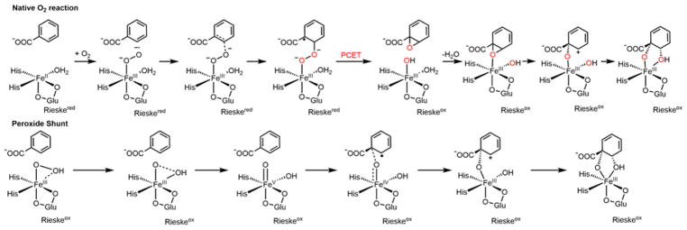
The results presented above give important insights into the reactivity of the RDOs. First, the peroxide shunt reaction, which from NRVS has the side-on FeIII–hydroperoxo BZDOp as an intermediate, uses a different mechanism than the native FeII O2 reaction, as shown in Scheme 3, bottom.
Scheme 3. Mechanisms As Developed in Section 3 for the Native O2 Reaction (Top) and the Peroxide Shunt Reaction (Bottom) in BZDOa.
aIn catalysis on the native O2 coordinate, the FeII resting state is regenerated by reduction of the Rieske and mononuclear sites, which leads to dissociation of the product. See Figure S8 for the stereochemistry of the epoxide species.
In the peroxide shunt, H2O2 binds to the FeIII catalytic site with an oxidized Rieske center to form BZDOp. The O–O bond then undergoes heterolytic cleavage with a barrier of 21.8 kcal/mol, generating an FeV(O)(OH) species that completes the cis-dihydroxylation reaction through electrophilic attack on the substrate. The calculated barrier is consistent with the slow product formation in the peroxide shunt reaction, and this mechanism is consistent with observations that a small amount of 16O exchanged product (10%) is formed when the peroxide shunt reaction is carried out with H218O2 in NDO.41 In contrast, the native FeII O2 reaction (Scheme 3, top) is calculated to proceed through an S = 2 FeIII–superoxo intermediate formed upon binding of O2 to the FeII site, which attacks the substrate to form an FeIII–peroxo bridgedaryl radical intermediate through a barrier of 13.7 kcal/mol. At this point, the reaction is driven by a PCET process, with the electron coming from the Rieske center and the proton from a nearby source. The FeIII–OH epoxide species formed by the PCET process then completes the reaction coordinate. BZDOp and the FeIII–superoxo intermediate are not in an equilibrium with each other, as BZDOp is significantly more stable thermodynamically, and conversion of the FeIII–superoxo to BZDOp is slow; thus, the reaction mechanisms for the peroxide shunt and native O2 reactions are not connected to each other. It should be noted that, as mentioned in the Introduction, side-on O2 intermediates have been trapped in crystals of NDO37 and CARDO39 upon addition of O2 to enzyme with reduced NHFeII and Rieske sites, and that these intermediates have oxidized Rieske centers and structures similar to that defined by NRVS for BZDOp.37,39 If proton transfer is more facile in the crystals, then PCET could occur at the superoxo stage to form a side-on FeIII–hydroperoxy intermediate in the crystal similar to BZDOp; at the crystallographic temperatures (~100 K), the barrier for O–O cleavage for this intermediate to react with substrate would be too high, as it is already high (21.8 kcal/mol) at 277 K. The rate of superoxo attack on the substrate could also be slower in the crystal: in NDO, O2 was added at −17 °C (versus 4 °C for the BZDO single turnover experiments). An alternative, and more likely, possibility is that proton transfer is more restricted in the crystal state. From Figures 6 and 8, the only thermodynamically favorable process after forming the FeIII–superoxo is ET from the Rieske to generate an unprotonated FeIII–peroxo species. From section 3.1, such a side-on FeIII–peroxo is also stable in BZDO, and from model studies a side-on FeIII–peroxo species is unreactive in electrophilic attack.10
Superoxide intermediates such as the one proposed here in the native O2 mechanism have been observed in two other mononuclear nonheme Fe enzyme classes: in IPNS15 and in an active site variant of the extradiol dioxygenase homoprotocatechuate 2,3-dioxygenase (HPCD).16 This provides some support for this intermediate in the RDOs; however, there are important differences between the RDOs and these other enzymes. The fact that a superoxo intermediate has been observed in IPNS and HPCD indicates that formation of this intermediate is thermodynamically favorable in those systems, while it is uphill by ~10 kcal/mol in BZDO. Previous computational studies have indeed found superoxo formation to be favorable in IPNS with its substrate bound to the FeII site and attributed this to substrate binding tuning down the FeII/FeIII reduction potential.14 In BZDO, the substrate does not bind directly to the Fe, making superoxo formation unfavorable. The transient formation of the superoxide intermediate in BZDO is therefore driven by the favorable thermodynamics of the PCET step that occurs upon formation of the peroxo bridge intermediate.
An FeIII–superoxo intermediate as the reactive intermediate in the native O2 reaction in the RDOs is consistent with the single turnover kinetics of BZDO, as discussed above. In addition to electrophilic attack on an aromatic ring, FeIII–superoxo complexes are also capable of performing HAA,88 consistent with other observed reactivities of the Rieske oxygenases that include monooxygenation,21 the radical clock reaction in NDO with norcarane,89 and the oxidative carbocyclization reactions catalyzed by the Rieske enzymes RedG and McpG.22,90 Further, the mechanism developed here for the native BZDO O2 reaction involves O–O cleavage that is not concerted with attack of the second O on the substrate, which is consistent with labeling experiments performed in the native O2 reaction of NDO, which show only a very small amount (~3%) of 16O exchange in the product when the reaction is carried out with 18O2.87
Finally, as described above, the barrier for the peroxide shunt reaction (21.8 kcal/mol, Table 1) is much higher than that of the native O2 reaction (13.7 kcal/mol, Table 2). The hydroperoxy intermediate BZDOp is thus less reactive than the FeIII–superoxo intermediate. However, if PCET were to occur at the FeIII–superoxo stage in the native O2 reaction, this would generate an FeIII–hydroperoxy intermediate at –12.9 kcal/mol (from Figure 8 and Table 2). This species can rearrange to form BZDOp by losing a water ligand with an additional 1 kcal/mol of free energy; the rate limiting O–O cleavage TS for BZDOp would then be at +9.9 kcal/mol relative to the FeII + O2 initial state (−12.9 kcal/mol +1 kcal/mol +21.8 kcal/mol). Thus, PCET to the superoxo species would be capable of giving the correct final product by going through the BZDOp mechanism without an additional barrier; however, this process would be rate limited by the PCET process. While there is a significant thermodynamic driving force for forming a hydroperoxo from a superoxo via PCET that would enable this reactivity, it is not sufficient to overcome the also significant reorganization energy associated with the catalytic and Rieske sites, leading to a slow rate of PCET. In contrast, the superoxo is highly reactive in electrophilic attack on the benzoate substrate, requiring only an additional 3.8 kcal/mol to reach the TS, with the total barrier of 13.7 kcal/mol (Table 2) consistent with the 190 s−1 rate-limiting step in single turnover. The high electrophilic reactivity of the superoxo therefore dominates over its PCET reactivity, which is slowed by the large superoxo to hydroperoxo reorganization energy. PCET later in the reaction coordinate is not rate limiting, as the large reorganization energy for PCET to the peroxo bridge is overcome by the highly favorable thermodynamics associated with reduction and cleavage of the peroxo O–O bond.
5. CONCLUSION
In summary, we have used NRVS spectroscopy to define the structure of the peroxide shunt intermediate in the RDOs and found this to be a high-spin side-on FeIII–hydroperoxy species. This intermediate performs cis-dihydroxylation through an initial heterolytic O–O cleavage through a large barrier, generating an FeV(O)(OH) species that then reacts with substrate. This peroxide shunt intermediate is not in equilibrium with a superoxo species on the native FeII/O2 reaction pathway, and the native pathway instead proceeds through an initial FeIII–superoxo intermediate that directly attacks the substrate through a relatively low total barrier. This process is uphill thermodynamically but driven by a highly favorable, fast PCET process that occurs after superoxo attack on the substrate. We have thus established separate mechanisms for the native O2 and peroxide shunt reactions in the RDOs and demonstrated the high reactivity of FeIII–superoxo relative to FeIII–hydroperoxo species in catalysis.
Supplementary Material
Acknowledgments
Funding for this work was provided by the National Institutes of Health (GM-40392 to E.I.S. and GM 118030 to J.D.L.) and JSPS KAKENHI (Grant No. 24221005 to M.S.). Synchrotron experiments at SPring-8 were performed with the approval of the Japan Synchrotron Radiation Research Institute (JASRI; proposal no. 2013B0105) and use of the Advanced Photon Source was supported by the Department of Energy, Office of Science, contract DE-AC-02-06CH11357.
Footnotes
Notes
The authors declare no competing financial interest.
ASSOCIATED CONTENT
The Supporting Information is available free of charge on the ACS Publications website at DOI: 10.1021/jacs.8b01822.
Methods for measuring pH dependence of native O2 reaction in BZDO; computational method for calculation of inner-sphere reorganization energy; analysis of PCET using the coordinated water as a proton source; analysis of PCET to a 5C peroxy-bridged intermediate followed by epoxide binding; EPR spectra of BZDOOX and BZDOp NRVS samples; 16O and 18O BZDOp NRVS data comparison; DFT structures of BZDOp candidates; LUMO of BZDOp; DFT structures of species along the BZDOp reaction coordinate; FMOs of intermediates in the BZDOp reaction coordinate; DFT structures of species along the superoxo attack coordinate; DFT structures of species along the epoxide formation and opening coordinate; 1D transit for direct attack of hydroxide on the epoxide; stopped flow traces of single turnover reactions of reduced BZDO with O2 in the presence of benzoate at pH 6.8 and 8.0; DFT structures of 5C peroxy bridge and Fe(OH) epoxide species; 1D transit for epoxide binding to Fe; table of NRVS and DFT vibrational parameters; table of DFT structural parameters for BZDOp candidate species (PDF)
References
- 1.Solomon EI, Brunold TC, Davis MI, Kemsley JN, Lee SK, Lehnert N, Neese F, Skulan AJ, Yang YS, Zhou J. Chem Rev. 2000;100:235–349. doi: 10.1021/cr9900275. [DOI] [PubMed] [Google Scholar]
- 2.Solomon EI, Light KM, Liu LV, Srnec M, Wong SD. Acc Chem Res. 2013;46:2725–2739. doi: 10.1021/ar400149m. [DOI] [PMC free article] [PubMed] [Google Scholar]
- 3.Solomon EI, Goudarzi S, Sutherlin KD. Biochemistry. 2016;55:6363. doi: 10.1021/acs.biochem.6b00635. [DOI] [PMC free article] [PubMed] [Google Scholar]
- 4.Chow MS, Eser BE, Wilson SA, Hodgson KO, Hedman B, Fitzpatrick PF, Solomon EI. J Am Chem Soc. 2009;131:7685–7698. doi: 10.1021/ja810080c. [DOI] [PMC free article] [PubMed] [Google Scholar]
- 5.Kovaleva EG, Lipscomb JD. Nat Chem Biol. 2008;4:186–193. doi: 10.1038/nchembio.71. [DOI] [PMC free article] [PubMed] [Google Scholar]
- 6.McDonald AR, Que L. Coord Chem Rev. 2013;257:414–428. [Google Scholar]
- 7.Eser BE, Barr EW, Frantom PA, Saleh L, Bollinger JM, Jr, Krebs C, Fitzpatrick PF. J Am Chem Soc. 2007;129:11334–11335. doi: 10.1021/ja074446s. [DOI] [PMC free article] [PubMed] [Google Scholar]
- 8.Sinnecker S, Svensen N, Barr EW, Ye S, Bollinger JM, Jr, Neese F, Krebs C. J Am Chem Soc. 2007;129:6168–6179. doi: 10.1021/ja067899q. [DOI] [PubMed] [Google Scholar]
- 9.Burger RM, Peisach J, Horwitz SB. J Biol Chem. 1981;256:1636–1644. [PubMed] [Google Scholar]
- 10.Cho J, Jeon S, Wilson SA, Liu LV, Kang EA, Braymer JJ, Lim MH, Hedman B, Hodgson KO, Valentine JS, Solomon EI, Nam W. Nature. 2011;478:502–505. doi: 10.1038/nature10535. [DOI] [PMC free article] [PubMed] [Google Scholar]
- 11.Kim YM, Cho K, Cho J, Wang B, Li C, Shaik S, Nam W. J Am Chem Soc. 2013;135:8838–8841. doi: 10.1021/ja404152q. [DOI] [PubMed] [Google Scholar]
- 12.Roach PL, Clifton IJ, Hensgens CMH, Shibata N, Schofield CJ, Hajdu J, Baldwin JE. Nature. 1997;387:827–830. doi: 10.1038/42990. [DOI] [PubMed] [Google Scholar]
- 13.Wood PM. Biochem J. 1988;253:287–289. doi: 10.1042/bj2530287. [DOI] [PMC free article] [PubMed] [Google Scholar]
- 14.Brown CD, Neidig ML, Neibergall MB, Lipscomb JD, Solomon EI. J Am Chem Soc. 2007;129:7427–7438. doi: 10.1021/ja071364v. [DOI] [PMC free article] [PubMed] [Google Scholar]
- 15.Tamanaha E, Zhang B, Guo Y, Chang WC, Barr EW, Xing G, StClair J, Ye S, Neese F, Bollinger JM, Jr, Krebs C. J Am Chem Soc. 2016;138:8862–8874. doi: 10.1021/jacs.6b04065. [DOI] [PMC free article] [PubMed] [Google Scholar]
- 16.Mbughuni MM, Chakrabarti M, Hayden JA, Bominaar EL, Hendrich MP, Muenck E, Lipscomb JD. Proc Natl Acad Sci U S A. 2010;107:16788–16793. doi: 10.1073/pnas.1010015107. [DOI] [PMC free article] [PubMed] [Google Scholar]
- 17.Christian GJ, Ye S, Neese F. Chem Sci. 2012;3:1600–1611. [Google Scholar]
- 18.Neibergall MB, Stubna A, Mekmouche Y, Munck E, Lipscomb JD. Biochemistry. 2007;46:8004–8016. doi: 10.1021/bi700120j. [DOI] [PMC free article] [PubMed] [Google Scholar]
- 19.Rivard BS, Rogers MS, Marell DJ, Neibergall MB, Chakrabarty S, Cramer CJ, Lipscomb JD. Biochemistry. 2015;54:4652–4664. doi: 10.1021/acs.biochem.5b00573. [DOI] [PMC free article] [PubMed] [Google Scholar]
- 20.Barry SM, Challis GL. ACS Catal. 2013;3:2362–2370. doi: 10.1021/cs400087p. [DOI] [PMC free article] [PubMed] [Google Scholar]
- 21.Resnick S, Lee K, Gibson D. J Ind Microbiol. 1996;17:438–457. [Google Scholar]
- 22.Sydor PK, Barry SM, Odulate OM, Barona-Gomez F, Haynes SW, Corre C, Song LJ, Challis GL. Nat Chem. 2011;3:388–392. doi: 10.1038/nchem.1024. [DOI] [PMC free article] [PubMed] [Google Scholar]
- 23.Ferraro DJ, Gakhar L, Ramaswamy S. Biochem Biophys Res Commun. 2005;338:175–190. doi: 10.1016/j.bbrc.2005.08.222. [DOI] [PubMed] [Google Scholar]
- 24.Gibson DT, Parales RE. Curr Opin Biotechnol. 2000;11:236–243. doi: 10.1016/s0958-1669(00)00090-2. [DOI] [PubMed] [Google Scholar]
- 25.Furukawa K. Curr Opin Biotechnol. 2000;11:244–249. doi: 10.1016/s0958-1669(00)00091-4. [DOI] [PubMed] [Google Scholar]
- 26.Wolfe MD, Altier DJ, Stubna A, Popescu CV, Munck E, Lipscomb JD. Biochemistry. 2002;41:9611–9626. doi: 10.1021/bi025912n. [DOI] [PubMed] [Google Scholar]
- 27.Martins BM, Svetlitchnaia T, Dobbek H. Structure. 2005;13:817–824. doi: 10.1016/j.str.2005.03.008. [DOI] [PubMed] [Google Scholar]
- 28.Kauppi B, Lee K, Carredano E, Parales RE, Gibson DT, Eklund H, Ramaswamy S. Structure. 1998;6:571–586. doi: 10.1016/s0969-2126(98)00059-8. [DOI] [PubMed] [Google Scholar]
- 29.Parales RE, Parales JV, Gibson DT. J Bacteriol. 1999;181:1831–1837. doi: 10.1128/jb.181.6.1831-1837.1999. [DOI] [PMC free article] [PubMed] [Google Scholar]
- 30.Wolfe MD, Parales JV, Gibson DT, Lipscomb JD. J Biol Chem. 2001;276:1945–1953. doi: 10.1074/jbc.M007795200. [DOI] [PubMed] [Google Scholar]
- 31.Ohta T, Chakrabarty S, Lipscomb JD, Solomon EI. J Am Chem Soc. 2008;130:1601–1610. doi: 10.1021/ja074769o. [DOI] [PMC free article] [PubMed] [Google Scholar]
- 32.Yang TC, Wolfe MD, Neibergall MB, Mekmouche Y, Lipscomb JD, Hoffman BM. J Am Chem Soc. 2003;125:7056–7066. doi: 10.1021/ja0214126. [DOI] [PubMed] [Google Scholar]
- 33.Friemann R, Lee K, Brown EN, Gibson DT, Eklund H, Ramaswamy S. Acta Crystallogr, Sect D: Biol Crystallogr. 2009;65:24–33. doi: 10.1107/S0907444908036524. [DOI] [PMC free article] [PubMed] [Google Scholar]
- 34.Inoue K, Ashikawa Y, Umeda T, Abo M, Katsuki J, Usami Y, Noguchi H, Fujimoto Z, Terada T, Yamane H, Nojiri H. J Mol Biol. 2009;392:436–451. doi: 10.1016/j.jmb.2009.07.029. [DOI] [PubMed] [Google Scholar]
- 35.Jakoncic J, Jouanneau Y, Meyer C, Stojanoff V. Biochem Biophys Res Commun. 2007;352:861–866. doi: 10.1016/j.bbrc.2006.11.117. [DOI] [PMC free article] [PubMed] [Google Scholar]
- 36.(JCSG), Joint Center for Structural Genomics. doi: 10.2210/pdb3N0Q/pdb. To be published. [DOI] [Google Scholar]
- 37.Karlsson A, Parales JV, Parales RE, Gibson DT, Eklund H, Ramaswamy S. Science (Washington, DC, U S) 2003;299:1039–1042. doi: 10.1126/science.1078020. [DOI] [PubMed] [Google Scholar]
- 38.Friemann R, Ivkovic-Jensen MM, Lessner DJ, Yu C, Gibson DT, Parales RE, Eklund H, Ramaswamy S. J Mol Biol. 2005;348:1139–1151. doi: 10.1016/j.jmb.2005.03.052. [DOI] [PubMed] [Google Scholar]
- 39.Ashikawa Y, Fujimoto Z, Usami Y, Inoue K, Noguchi H, Yamane H, Nojiri H. BMC Struct Biol. 2012;12:15. doi: 10.1186/1472-6807-12-15. [DOI] [PMC free article] [PubMed] [Google Scholar]
- 40.Ferraro DJ, Okerlund A, Brown E, Ramaswamy S. IUCrJ. 2017;4:648–656. doi: 10.1107/S2052252517008223. [DOI] [PMC free article] [PubMed] [Google Scholar]
- 41.Wolfe MD, Lipscomb JD. J Biol Chem. 2003;278:829–835. doi: 10.1074/jbc.M209604200. [DOI] [PubMed] [Google Scholar]
- 42.Davis MI, Wasinger EC, Decker A, Pau MYM, Vaillancourt FH, Bolin JT, Eltis LD, Hedman B, Hodgson KO, Solomon EI. J Am Chem Soc. 2003;125:11214–11227. doi: 10.1021/ja029746i. [DOI] [PubMed] [Google Scholar]
- 43.Rieske JS, MacLennan DH, Coleman R. Biochem Biophys Res Commun. 1964;15:338–344. [Google Scholar]
- 44.Ohta T, Lipscomb JD, Solomon EI. Unpublished results. [Google Scholar]
- 45.Seto M, Yoda Y, Kikuta S, Zhang XW, Ando M. Phys Rev Lett. 1995;74:3828–3831. doi: 10.1103/PhysRevLett.74.3828. [DOI] [PubMed] [Google Scholar]
- 46.Sturhahn W, Toellner TS, Alp EE, Zhang X, Ando M, Yoda Y, Kikuta S, Seto M, Kimball CW, Dabrowski B. Phys Rev Lett. 1995;74:3832–3835. doi: 10.1103/PhysRevLett.74.3832. [DOI] [PubMed] [Google Scholar]
- 47.Liu LV, Bell CB, III, Wong SD, Wilson SA, Kwak Y, Chow MS, Zhao J, Hodgson KO, Hedman B, Solomon EI. Proc Natl Acad Sci U S A. 2010;107:22419–22424. doi: 10.1073/pnas.1016323107. [DOI] [PMC free article] [PubMed] [Google Scholar]
- 48.Wong SD, Srnec M, Matthews ML, Liu LV, Kwak Y, Park K, Bell CB, III, Alp EE, Zhao J, Yoda Y, Kitao S, Seto M, Krebs C, Bollinger JM, Jr, Solomon EI. Nature. 2013;499:320–323. doi: 10.1038/nature12304. [DOI] [PMC free article] [PubMed] [Google Scholar]
- 49.Park K, Li N, Kwak Y, Srnec M, Bell CB, III, Liu LV, Wong SD, Yoda Y, Kitao S, Seto M, Hu M, Zhao J, Krebs C, Bollinger JM, Jr, Solomon EI. J Am Chem Soc. 2017;139:7062–7070. doi: 10.1021/jacs.7b02997. [DOI] [PMC free article] [PubMed] [Google Scholar]
- 50.Sutherlin KD, Liu LV, Lee YM, Kwak Y, Yoda Y, Saito M, Kurokuzu M, Kobayashi Y, Seto M, Que L, Nam W, Solomon EI. J Am Chem Soc. 2016;138:14294. doi: 10.1021/jacs.6b07227. [DOI] [PMC free article] [PubMed] [Google Scholar]
- 51.Cohen-Bazire G, Sistrom WR, Stanier RY. J Cell Comp Physiol. 1957;49:25–68. doi: 10.1002/jcp.1030490104. [DOI] [PubMed] [Google Scholar]
- 52.Smith MC, Xiao Y, Wang H, George SJ, Coucouvanis D, Koutmos M, Sturhahn W, Alp EE, Zhao J, Cramer SP. Inorg Chem. 2005;44:5562–5570. doi: 10.1021/ic0482584. [DOI] [PubMed] [Google Scholar]
- 53.Sturhahn W. Hyperfine Interact. 2000;125:149–172. [Google Scholar]
- 54.Frisch MJ, Trucks GW, Schlegel HB, Scuseria GE, Robb MA, Cheeseman JR, Scalmani G, Barone V, Mennucci B, Petersson GA, Nakatsuji H, Caricato M, Li X, Hratchian HP, Izmaylov AF, Bloino J, Zheng G, Sonnenberg JL, Hada M, Ehara M, Toyota K, Fukuda R, Hasegawa J, Ishida M, Nakajima T, Honda Y, Kitao O, Nakai H, Vreven T, Montgomery JA, Jr, Peralta JE, Ogliaro F, Bearpark M, Heyd JJ, Brothers E, Kudin KN, Staroverov VN, Kobayashi R, Normand J, Raghavachari K, Rendell A, Burant JC, Iyengar SS, Tomasi J, Cossi M, Rega N, Millam NJ, Klene M, Knox JE, Cross JB, Bakken V, Adamo C, Jaramillo J, Gomperts R, Stratmann RE, Yazyev O, Austin AJ, Cammi R, Pomelli C, Ochterski JW, Martin RL, Morokuma K, Zakrzewski VG, Voth GA, Salvador P, Dannenberg JJ, Dapprich S, Daniels AD, Farkas Ö, Foresman JB, Ortiz JV, Cioslowski J, Fox DJ. Gaussian 09, Revision D. 01. Gaussian, Inc; Wallingford, CT: 2009. [Google Scholar]
- 55.Becke AD. J Chem Phys. 1993;98:5648–5652. [Google Scholar]
- 56.Lee CT, Yang WT, Parr RG. Phys Rev B: Condens Matter Mater Phys. 1988;37:785–789. doi: 10.1103/physrevb.37.785. [DOI] [PubMed] [Google Scholar]
- 57.Vosko SH, Wilk L, Nusair M. Can J Phys. 1980;58:1200–1211. [Google Scholar]
- 58.Stephens PJ, Devlin FJ, Chabalowski CF, Frisch MJ. J Phys Chem. 1994;98:11623–11627. [Google Scholar]
- 59.McLean AD, Chandler GS. J Chem Phys. 1980;72:5639–5648. [Google Scholar]
- 60.Krishnan R, Binkley JS, Seeger R, Pople JA. J Chem Phys. 1980;72:650–654. [Google Scholar]
- 61.Hay JP. J Chem Phys. 1977;66:4377–4384. [Google Scholar]
- 62.Roos B, Veillard A, Vinot G. Theor Chim Acta. 1971;20:1–11. [Google Scholar]
- 63.Raghavachari K, Trucks GW, Pople JA, Headgordon M. Chem Phys Lett. 1989;157:479–483. [Google Scholar]
- 64.Liu LV, Hong S, Cho J, Nam W, Solomon EI. J Am Chem Soc. 2013;135:3286–3299. doi: 10.1021/ja400183g. [DOI] [PMC free article] [PubMed] [Google Scholar]
- 65.Cramer CJ, Truhlar DG. Chem Rev. 1999;99:2161–2200. doi: 10.1021/cr960149m. [DOI] [PubMed] [Google Scholar]
- 66.Johnson M, Zaretskaya I, Raytselis Y, Merezhuk Y, McGinnis S, Madden TL. Nucleic Acids Res. 2008;36:5–9. doi: 10.1093/nar/gkn201. [DOI] [PMC free article] [PubMed] [Google Scholar]
- 67.Park K, Solomon EI. Can J Chem. 2014;92:975. doi: 10.1139/cjc-2014-0067. [DOI] [PMC free article] [PubMed] [Google Scholar]
- 68.Tenderholt A. gennrvs, Python script Version 28. 2009 Available at http://www.stanford.edu/group/solomon/gennrvs/gennrvs.py.txt.
- 69.Kieber-Emmons MT. Lumo, Version 1.0.1. 2012. [Google Scholar]
- 70.Tenderholt AT. QMForge, Version 2.1. 2007. [Google Scholar]
- 71.Geronimo I, Paneth P. Phys Chem Chem Phys. 2014;16:13889–13899. doi: 10.1039/c4cp01030b. [DOI] [PubMed] [Google Scholar]
- 72.Bassan A, Blomberg MRA, Siegbahn PEM. JBIC, J Biol Inorg Chem. 2004;9:439–452. doi: 10.1007/s00775-004-0537-0. [DOI] [PubMed] [Google Scholar]
- 73.Pabis A, Geronimo I, Paneth P. J Phys Chem B. 2014;118:3245–3256. doi: 10.1021/jp4076299. [DOI] [PMC free article] [PubMed] [Google Scholar]
- 74.Chen H, Lai W, Yao J, Shaik S. J Chem Theory Comput. 2011;7:3049–3053. doi: 10.1021/ct200614g. [DOI] [PubMed] [Google Scholar]
- 75.Marcus RA. J Phys Chem. 1968;72:891–899. [Google Scholar]
- 76.Gilmore K, Alabugin IV. Chem Rev. 2011;111:6513–6556. doi: 10.1021/cr200164y. [DOI] [PubMed] [Google Scholar]
- 77.Kuznetsov AM, Zueva EM, Masliy AN, Krishtalik LI. Biochim Biophys Acta, Bioenerg. 2010;1797:347–359. doi: 10.1016/j.bbabio.2009.12.004. [DOI] [PubMed] [Google Scholar]
- 78.Ullmann GM, Noodleman L, Case DA. JBIC, J Biol Inorg Chem. 2002;7:632–639. doi: 10.1007/s00775-002-0342-6. [DOI] [PubMed] [Google Scholar]
- 79.Donald WA, Leib RD, O’Brien JT, Williams ER. Chem - Eur J. 2009;15:5926–5934. doi: 10.1002/chem.200900334. [DOI] [PMC free article] [PubMed] [Google Scholar]
- 80.Schaefer AW, Kieber-Emmons MT, Adam SM, Karlin KD, Solomon EI. J Am Chem Soc. 2017;139:7958–7973. doi: 10.1021/jacs.7b03292. [DOI] [PMC free article] [PubMed] [Google Scholar]
- 81.Brown EN, Friemann R, Karlsson A, Parales JV, Couture MMJ, Eltis LD, Ramaswamy S. JBIC, J Biol Inorg Chem. 2008;13:1301–1313. doi: 10.1007/s00775-008-0413-4. [DOI] [PubMed] [Google Scholar]
- 82.Bassan A, Blomberg MRA, Borowski T, Siegbahn PEM. J Phys Chem B. 2004;108:13031–13041. [Google Scholar]
- 83.Marcus RA. J Chem Phys. 1956;24:966–978. [Google Scholar]
- 84.Cowley RE, Tian L, Solomon EI. Proc Natl Acad Sci U S A. 2016;113:12035–12040. doi: 10.1073/pnas.1614807113. [DOI] [PMC free article] [PubMed] [Google Scholar]
- 85.Auer B, Fernandez LE, Hammes-Schiffer S. J Am Chem Soc. 2011;133:8282–8292. doi: 10.1021/ja201560v. [DOI] [PubMed] [Google Scholar]
- 86.Sigfridsson E, Olsson MHM, Ryde U. Inorg Chem. 2001;40:2509–2519. doi: 10.1021/ic000752u. [DOI] [PubMed] [Google Scholar]
- 87.Jeffrey AM, Yeh HJC, Jerina DM, Patel TR, Davey JF, Gibson DT. Biochemistry. 1975;14:575–584. doi: 10.1021/bi00674a018. [DOI] [PubMed] [Google Scholar]
- 88.Chiang CW, Kleespies ST, Stout HD, Meier KK, Li PY, Bominaar EL, Que L, Münck E, Lee WZ. J Am Chem Soc. 2014;136:10846–10849. doi: 10.1021/ja504410s. [DOI] [PMC free article] [PubMed] [Google Scholar]
- 89.Chakrabarty S, Austin RN, Deng D, Groves JT, Lipscomb JD. J Am Chem Soc. 2007;129:3514–3515. doi: 10.1021/ja068188v. [DOI] [PMC free article] [PubMed] [Google Scholar]
- 90.Zhou J, Kelly WL, Bachmann BO, Gunsior M, Townsend CA, Solomon EI. J Am Chem Soc. 2001;123:7388–7398. doi: 10.1021/ja004025+. [DOI] [PubMed] [Google Scholar]
Associated Data
This section collects any data citations, data availability statements, or supplementary materials included in this article.


