Abstract
Carbon fiber (CF) ankle-foot orthoses (AFOs) can improve gait by increasing ankle plantar-flexor power and improving plantar-flexor ankle joint moment and energy efficiency compared with posterior leaf spring AFOs made of thermoplastic. However, fabricating a CF AFO to optimize the performance of the individual user may require multiple AFOs and expensive fabrication costs. Finite element analysis (FEA) models were developed to predict the mechanical behavior of AFOs in this study. Three AFOs, two made of CF composite material and one made of thermoplastic material, were fabricated and then mechanically tested to produce force-displacement data. The FEA models were validated by comparing model predictions with mechanical testing data performed under the same loading and boundary conditions. The actual mechanical testing demonstrated that CF performs better than thermoplastic. The simulation results showed that FEA models produced accurate predictions for both types of orthoses. The relative error of the energy return ratio predicted by the CF AFO FEA model developed in this study is less than 3%. We conclude that highly accurate FEA models will allow orthotists to improve CF AFO fabrication without wasting resources (time and money) on trial and error fabrications that are expensive and do not consistently improve AFO and user performance.
Keywords: ankle-foot orthosis, boundary condition, carbon fiber, computed tomography, energy return, finite element analysis, fracture, mechanical property, posterior leaf spring, thermoplastic
INTRODUCTION
In the United States, approximately 866,000 people use a lower-limb orthosis to assist them in daily activities [1]. Ankle-foot orthoses (AFOs) mechanically assist patients with gait impairments by improving limb control and joint positioning. Posterior leaf spring (PLS) AFOs have been made of thermoplastics due to easy molding and rapid fabrication, but these orthoses have very low energy storage and energy return capabilities and thus are unable to assist with propulsion during walking. Composite materials, such as carbon fiber (CF), have been suggested as an alternative to thermoplastics. Studies have shown that CF AFOs improve ankle plantar-flexor power, plantar-flexor ankle joint moment, walking speed, and stride length and decrease energy cost compared with AFOs [2–4]. However, CF AFOs are difficult and expensive to fabricate. Multiple design modifications are often required to produce an AFO that is comfortable and results in improved gait performance. Unlike thermoplastic AFOs, CF AFOs cannot be remolded if modifications are required. Often, lack of knowledge about the interaction between CF AFO material properties, orthosis design, and patient-specific characteristics prevent some patients from experiencing the full benefits of the power restoration potential without design modifications requiring refabrication. In order to reduce the CF AFO refabrication rate and optimize user performance, both computational modeling and validation with experimental testing are needed to allow orthotists and researchers to design and optimally fabricate proper CF AFOs for their patients.
Recently, researchers have used finite element analysis (FEA) modeling to simulate and optimize novel AFO designs [5–8]. A fully parameterized computer-aided design (CAD) model uses a discrete set of parameters to fully describe and control a model’s design [9]. FEA of CAD models enables prediction of in situ stresses and strains through the application of boundary conditions that mimic real-world conditions. In the field of prosthetics and orthotics, FEA has been used to evaluate and design a variety of devices [10–13]. FEA can also predict stress distribution and material deformation patterns [5–6,8,14] and can determine the orthosis dimensions needed to mimic design characteristics of commercial orthoses [15]. FEA of fully parameterized CAD models may hold great potential for rapidly identifying optimal PLS AFO functional characteristics, such as bending stiffness.
CF technology and design features used in prosthetic feet have recently been incorporated into AFOs. The limited evidence available has found that the CF AFO, compared with the traditional AFO, improves ankle plantar-flexor power by 15 to 97 percent [16]; increases plantar-flexor ankle moment by 7 to 27 percent [2], walking speed by 6 to 30 percent [4], and stride length by 4 to 9 percent [3]; and decreases energy cost by 12 percent [17]. These findings are exciting and speak to the promise of improved function when CF is incorporated into AFO design. However, the variability in the improvement of plantar-flexor power and walking speed across studies mirror the mixed individual patient reports of CF AFO performance.
By creating a tool to predict energy storage and release based on a patient’s physical characteristics and gait parameters, AFO prescription could be more standardized and the function of AFOs increased for many individuals. Although it would be possible to create this tool through the gathering of empirical data, utilizing software capable of modeling the complex stress and stains occurring within the AFO is more efficient. After validating the model, computer simulations can determine optimal configurations for AFOs. Moreover, instead of costly experimental testing, FEA modeling allows for a cost-efficient alternative to investigate design parameters (fiber orientation, thickness, number of plies, type of CF plies) to improve AFO performance and reduce manufacturing costs. The main purpose of this study is to begin model validation by comparing stress concentrations measured in bench-top testing with what is predicted by FEA modeling. These FEA models will help predict orthosis performance under different loading conditions, such as walking or running, and possible failure and fatigue life before the fabrication process.
METHODS
Background of Mechanical Properties
Materials are commonly classified based on their force-displacement (F-D) curves. The F-D curve is created by experimental testing. The relationship between force and displacement can then be used to calculate elastic energy (E) using Equation 1:
| (1) |
where F = force and d = perpendicular distance.
Ankle-Foot Orthosis Design
High-temperature thermoplastic (e.g., polypropylene) AFOs are often prescribed to improve patient safety and stability. AFOs are most often used in individuals with ankle dorsiflexor muscle weakness to prevent foot drop during the swing phase of gait and to hold the foot in an optimal position for contacting the ground. The polypropylene homopolymer material used in fabrication has poor energy storage and return capabilities. The AFO provides minimal restoration of the ankle power needed to propel the body forward at the end of the stance phase of walking, thereby limiting walking speed and higher levels of activities [18–20]. CF technology and rear-support design features have recently been incorporated into AFOs. The CF composite is a lightweight material that is flexible, strong, and able to be easily manipulated to change its loading capacity and stiffness. CF AFOs are fabricated by layering sheets of CF cloth over a mold with epoxy preimpregnated into the CF. The thermoplastic and CF AFOs were fabricated by Orthotic & Prosthetic Design (St. Louis, Missouri).
Properties and Structure of Ankle-Foot Orthoses
Carbon Fiber Ankle-Foot Orthosis Properties
CF composites are constructed by laying fibers out in sheets, or plies, then impregnating them with a resin that is later cured at high temperatures. These plies are stacked in order to get the desired material properties for the application. Because of the CF’s material properties, a single ply layer of a composite material will respond differently and have a different stiffness when loaded in the fiber direction, transverse direction, or angled between these two. The AFO’s geometric complexity and stacking sequence made it impractical to define the anisotropic properties of the material at this early stage of the project; instead, the material was treated as a homogeneous isotropic material. The CF used to construct the test AFOs used DA 4090/DA 4092 (APCM LLC; Plainfield, Connecticut). Table 1 defines the density and Poisson ratio [21]. A Poisson ratio of 0.5 was used to treat the AFO as an incompressible material. The true Poisson ratio would depend on the construction of the laminate, but the assumption to treat it as incompressible was made because the stresses experienced were less than yield stress, an assumption confirmed because reaching yield stress would cause delamination of plies and failure of the material.
Table 1.
Finite element analysis (FEA) model material properties used based on DA 4090/DA 4092 (APCM LLC; Plainfield, Connecticut).
| Property | FEA Model |
|---|---|
| Carbon Fiber Material | DA 4090/4092 SI (mm) |
| Density (g/mm3) | 1.44 (DA 409 U/G35 150) |
| Poisson Ratio | 0.5 |
| Tensile Strength (MPa) | 437 |
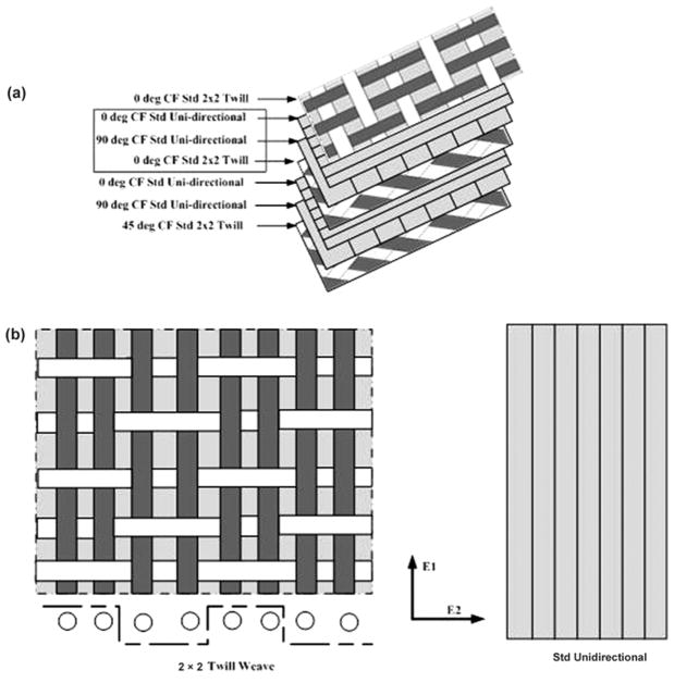
In this study, the CF AFO was assumed to be a single section (shell, composite) composed of different layers with alternating orientations. Figure 1(a) shows the orientation angles of layers. The outermost layer is the CF Standard (Std) 2 × 2 Twill (Figure 1(b)), and the underlying layers are composed of CF Std Unidirectional (Figure 1(b)) and CF Std 2 × 2 Twill with various orientation angles; the minimum repeat section is given by the red rectangle in Figure 1(a). Each layer has a thickness of 0.2 mm, and the 0.2 mm fibers are arranged in a symmetrical weave pattern and have an equal number of identical yarns per centimeter. The long fibers (warp) are oriented symmetrically. Each ply’s warp is +45° from the long axis of the warp of the ply below. This symmetry helps avoid thermal twisting during cooldown after the cure cycle. The layup is also balanced with the same number of fibers in each direction. This arrangement helps avoid twisting under an applied load. Table 2 lists the mechanical properties of CF used to fabricate the sample AFOs [21].
Figure 1.
Structure of carbon fiber (CF) ankle-foot orthosis (AFO) used for design. (a) Layers and orientation of CF AFO. (b) Fiber structures of Std 2 × 2 Twill Weave and Std Unidirectional layer. Std = standard.
Table 2.
Mechanical properties of carbon fiber (CF) composite materials.
| Property | CF Std Unidirectional | CF Std 2 × 2 Twill |
|---|---|---|
| Longitudinal Modulus (GPa) E1 | 70 | 17 |
| Transverse Modulus (GPa) E2 | 70 | 17 |
| In-Plane Shear Modulus (GPa) G12 | 5 | 33 |
| In-Plane Shear Strength (MPa) S | 90 | 260 |
Std = standard.
Polypropylene Ankle-Foot Orthosis Properties
The orthosis used for testing is a PLS. This orthosis stabilizes ankle and subtalar motion and also minimizes knee flexion. It is made of polypropylene that was 1/4 in. before being molded to fit the patient’s limb. The trim lines at the ankle are anterior to the ankle. This orthosis’s greater stability is due to the thickness of the plastic and the fact that the plastic wraps around the foot as much as is possible while still allowing the wearer to get his or her foot into the orthosis. The amount of plastic used to achieve this stability requires a larger shoe size. A ductile polymer such as polypropylene exhibits hyperelastic and viscoelastic properties. The material is nonlinear both in the loading and unloading directions and as the maximum strain is increased. The density of the material used for the thermoplastic brace in this study is 0.9 g/m3, and the Young modulus, Poission ratio, and tensile strength are 2,400 MPa, 0.43, and 30 MPa, respectively.
Structure of Ankle-Foot Orthoses
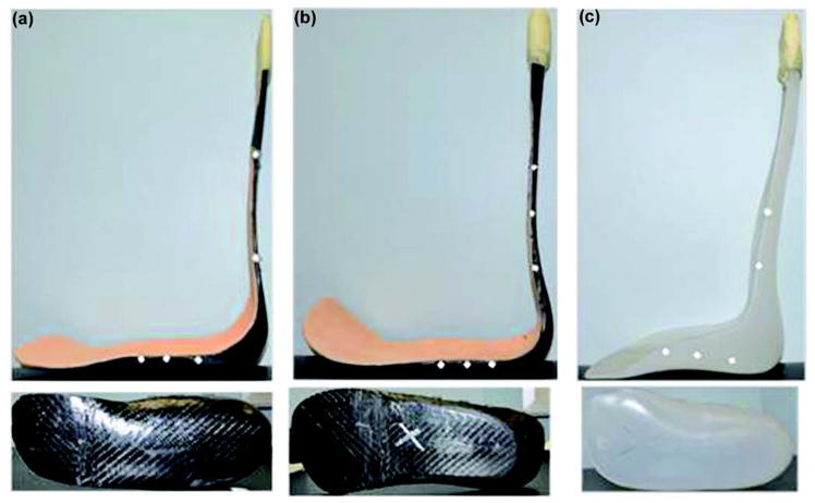
Three AFOs, two CF and one polypropylene, were fabricated and mechanically tested in this study (Figure 2). AFO1 is a CF AFO (Figure 2(a)): the shank is 18 layers, the mid-foot is 9 layers, and the toe is 4 layers; AFO2 is another CF AFO (Figure 2(b)): the shank is 24 layers, the mid-foot is 9 layers, and the toe is 4 layers; and AFO3 is a polypropylene AFO (Figure 2(c)). Model simulations were then created using FEA software (SIMULIA Abaqus version 6.12, Dassault Systèmes Americas Corp; Waltham, Massachusetts).
Figure 2.
Ankle-foot orthoses (AFOs) used in current study. (a) AFO1, (b) AFO2, and (c) AFO3.
Mechanical Testing and Finite Element Analysis Modeling
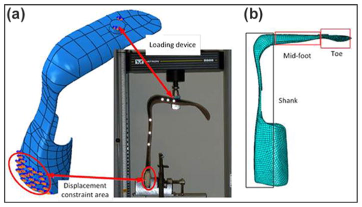
The thermoplastic and CF AFOs were tested using an Instron 5866 electromechanical materials testing system (Instron; Norwood, Massachusetts). Figure 3(a) shows the testing setup of a CF AFO. All bench-top tests were run in triplicate to ensure accuracy and repeatability. One reflective marker was placed on the Instron system to provide a recordable reference point. The reflective marker was tracked in three-dimensional (3D) space and recorded by a motion capture system (Qualisys AB; Gothenburg, Sweden) at 60 Hz. Due to the different material properties, the CF AFO was loaded to 1,000 N while the thermoplastic AFO was loaded to 150 N during testing. Multiple trials were run on each AFO with loading rates of 8 mm/s. The Instron and Qualysis systems were used to collect both load and displacement data, and the energy return of the orthosis was determined by calculating the area under the unloading curve of the F-D data.
Figure 3.
(a) Bench-top testing setup and (b) finite element analysis modeling setting.
Computed tomography (CT) scans were performed to acquire the geometry data for two CF AFOs and one thermoplastic AFO using a research-dedicated 64-slice CT scanner (SOMATOM Sensation 64 eco; Siemens Medical Solutions USA; Malvern, Pennsylvania). Conversion of AFO CT image data to triangulated surface models was performed using Mimics version 13.1 (Materialize; Leuven, Belgium). The data were filtered using a median filter with a radius of 1 to reduce nonstructured image noise, then were output in stereolithography (STL) standard format. These CT scans, in STL file format, were imported into SIMULIA Abaqus version 6.12 FEA software for creating the volumetric model, meshing, and applying boundary conditions. Figure 3(b) shows the 3D FEA model. The CF AFO was divided into three parts (shank, mid-foot, and toe) according to the number of CF plies. To model the mesh necessary to run the simulation, the CF plies were assumed to act uniformly at any given cross section. This was acceptable because a significant variance between plies would result in delamination and failure of the material. A tet (tetrahedral) element shape was used to best fit the shape. The element type used a quadratic geometric order with the improved surface stress formulation setting on looking for 3D stress. The 276 faces of the geometry were seeded by 74,568 elements during the meshing process before simulations were run.
For the CF AFOs, the FEA model was assumed to be a shell composite composed of CF and resin with material properties affected by lamina-type and fiber orientation. When a CF-composite AFO is loaded, all loads are distributed between the fibers and resin. This means that the stress in the composite is equal to the sum of all stresses in the fibers and resin (Equation 2):
| (2) |
where σt = total stress in the composite material; σr and σf = resin and fiber stress tensors, respectively; ρ = volume fraction; f = fiber; r = resin; i = ith direction; and n = total number of fibers. The thermoplastic AFO model was assumed to be a homogeneous solid of elastic, isotropic, and plastic material properties.
Boundary conditions were imposed to simulate the dynamic loads that occurred during bench-top testing and from experimental sessions of subjects during gait (Figure 3(a)). The simulation was designed to replicate the bench-top testing performed on the sample AFOs. This test was intended to replicate the stress and strains experienced by the AFO when being worn by a patient; however, limitations with testing equipment inhibit a perfect match. Stationary boundary conditions were placed on a posterior face of the AFO approximately centered behind where the calf straps are located (Figure 3(a)). This replicated both where the AFO’s motion is inhibited by being strapped to the patient and where the bench-top tests held the sample AFOs. For the simulation to accurately match the bench-top testing, a load ~1.3× the patient weight was chosen. The force was concentrated on the loading device (shown in Figure 3(a), set as rigid during simulation), and the contact friction coefficient between the force cylinder and the AFO sole was set as 0.1 [22]. The initial simulation step had the AFO constrained with the boundary conditions but experiencing no load, which was seen by its undeformed shape. The initial contact location was approximately where the force was applied in the laboratory tests. The loading device only had y-direction displacement during simulation. Adding the displacement of the loading device through the contact force between the device and AFO sole, the reaction forces could be determined during compression. During the AFO Instron system bench-top testing, the load transferred to the sole of the foot (approximately below the middle of the third metatarsal) through a cylindrical load cell. Therefore, we added a rigid cylinder to the FEA model at that location and applied force superiorly through the sole to replicate the reaction forces during compression that were experienced during the Instron system bench-top testing. The loading rates were 8 mm/s to replicate those applied in the bench-top test. The contact loading force and displacement of the AFO were outputted and compared with bench-top testing results.
PREDICTION AND RESULTS
The FEA models were analyzed by an Intel core i5–3210M processor at 2.5 GHz computer with 4 GB of RAM (Intel; Santa Clara, California). The material properties of the AFOs are set by the CF and polypropylene given previously. The FEA simulation replicated the bench-top testing of the three AFOs used in this study. Stationary boundary conditions were placed on the posterior face of an AFO approximately centered behind where the calf straps were located. This was done to replicate both where the AFO’s motion is inhibited by being strapped to the patient and to match where the bench-top tests held the sample AFOs. Experimental mechanical testing was performed to determine the force versus displacement relationship of each brace to validate FEA results.
Bench-Top Test and Finite Element Analysis Comparison
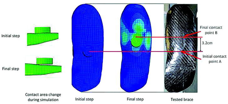
To validate the FE model, we conducted a comparative study between the F-D relationship obtained by bench-top testing and from the FEA of AFO1 (Figure 4). The initial step of the simulation has the AFO constrained with the boundary conditions but experiencing no load, which is seen by its undeformed shape, shown in the initial step of Figure 5. The final step of this FEA has the same constraint and boundary conditions. However, the load applied to the loading device is 1,000 N. Figure 4 shows that the predicted results of AFO1 match well (nominal root mean square is 3.1%) with the experimental results. Due to deformation in the AFO, the contact point between the orthosis and the applied load changed during the test (Figure 5). The FEA predicted that this displacement in applied load would be 3 cm. This was very close to the experimental results that showed 3.2 cm displacement.
Figure 4.
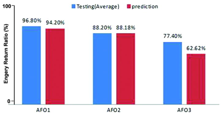
Energy return ratio comparison between testing and prediction (relative errors for ankle-foot orthosis [AFO] 1, AFO2, and AFO3 are 2.68%, 0.02%, and 19.09%, respectively).
Figure 5.
Contact point moving comparison between testing and finite element analysis.
Energy Return Analysis
The F-D curves of the FEA model matched well with experimental testing. It is therefore possible to accurately calculate the energy return ratio of the orthosis using FEA by calculating the area under the loading and unloading curves. Figure 6 shows the loading and unloading curves of different AFOs given by bench-top testing and FEA. The F-D behavior for the CF and thermoplastic AFOs were very different. The CF AFO had a relatively linear F-D loading curve with high stiffness, while the thermoplastic AFO shows viscoelastic behavior with low stiffness. Besides nonlinearity, the thermoplastic AFO only reached approximately 150 N during the bench-top testing before undergoing significant deformation. The CF AFO was able to reach a much higher loading, 1,000 N, with little deformation. Figure 4 shows the predicted energy return ratios of different braces. The FEA models accurately predicted the energy return ratio of CF AFOs measured during testing (relative error was 2.68% for AFO1 and 0.02% for AFO2); however, the thermoplastic prediction was inaccurate (relative error reached 19.87%) due to the complexity of plasticity and the rough approximation used to predict the huge displacements in the orthosis at higher loads. The thermoplastic FEA model was able to predict the elastic and early plastic regions of AFO3 with better accuracy (relative error was 5.31%).
Figure 6.
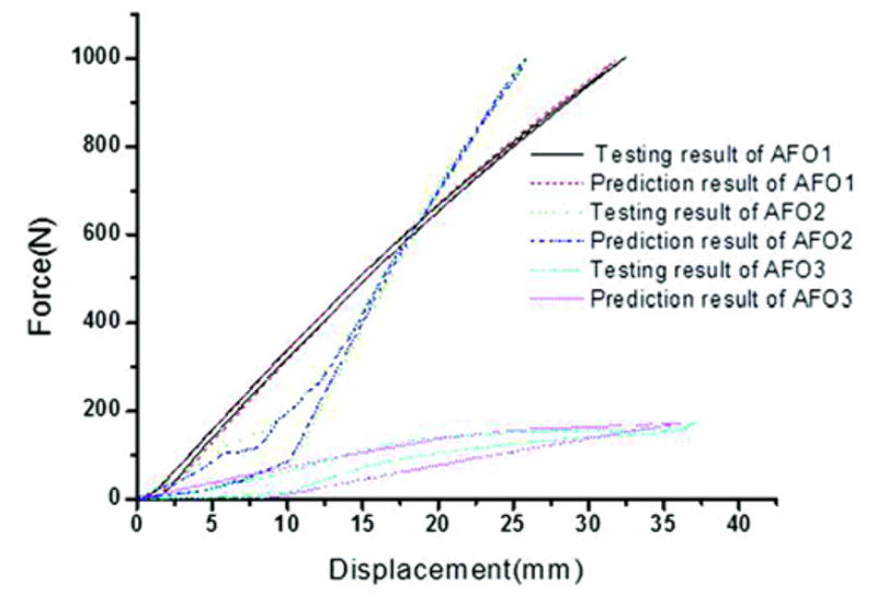
Loading and unloading curves of different ankle-foot orthoses (AFOs) given by bench-top testing and finite element analysis.
Fracture Analysis
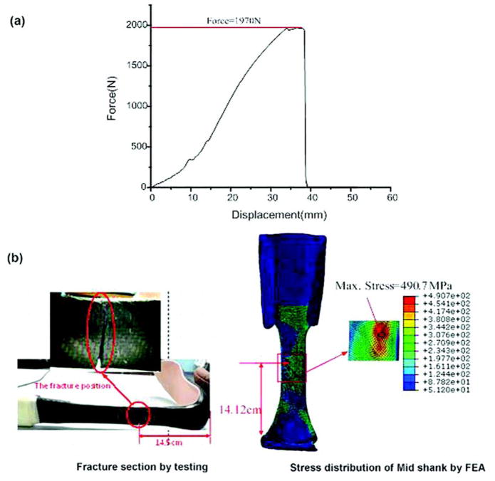
After completion of the mechanical testing, CF AFO2 was loaded until structural failure occurred. This fracture analysis was performed to determine the maximum load the AFO can bear and to validate the FEA model in this study. Figure 7(a) shows the F-D curve. Fracture occurred at a load of 1,970 N, and the fracture area was located at the mid-shank (Figure 7(b)). Based on this mechanical testing result, the load was increased to 1,970 N during the FEA model simulation. Figure 7(b) shows the Mises stress distribution of mid-shank determined from the FEA result. The stress in the mid-shank area exceeded 437 MPa, which is the yield stress of the CF. The maximum stress reached 490.7 MPa, and the predicted fracture distance from the soles of the CF AFOs was 14.2 cm, very close to the 14.5 cm given by the experimental result.
Figure 7.
Fracture testing and simulation. (a) Force versus displacement curve of ankle-foot orthosis (AFO) 2 during destructive testing. (b) Fracture area of AFO2. FEA = finite element analysis, Max = maximum.
DISCUSSION
The bench-top mechanical testing demonstrated that thermoplastic and CF AFOs behave very differently. The CF AFO was able to support loading in excess of 1,000 N, which is the approximate amount of force on the AFO during walking for a 225 lb man. The thermoplastic AFO behaved very nonlinearly, due to the viscoelastic and plastic properties of thermoplastics, and was unable to support loads above 150 N without undergoing major deformations. Syngellakis et al. stated that material nonlinearity exists in polypropylene when it is loaded beyond a certain range [23]. This phenomenon was shown clearly in this study (Figure 6).
A passive dynamic and energy storage orthosis are of interest to further improve gait [8]. These devices use their material properties (component thickness, AFO shape, springs, and fluid pressure dynamics) to provide support and mechanical energy return during gait [24]. Hafner et al. reviewed the literature on energy storage prosthetic devices (feet), highlighting nomenclature confusion and variations in measuring energy storage and energy return features [17]. A prosthetic foot consists of a compressible heel and a flexible keel spring that acts as an elastic spring and returns energy to the patient. Considered to be more advanced, CF shank prosthetic feet with a heel spring were introduced in 1987. Both of these prosthetic feet designs are considered passive devices. Like these prosthetics, energy storage orthotics store energy during weight-bearing in the stance phase and release it as the foot unloads for swing initiation [25]. The peak power produced by the prosthetic foot can be 15 to 20 percent of normal push-off, reducing the energy (as measured by oxygen consumption) expended by the patient [24]. The CF AFOs used in this study were able to return more than 88 percent of energy from a 1,000 N load. The thermoplastic AFO returned 77.4 percent of a 150 N load, deformed more than CF AFOs, and increased energy cost 19.4 percent (AFO1 – AFO3 = 96.8% – 77.4%) and 10.8 percent (AFO2 – AFO3 = 88.2% – 77.4%) (Figure 4). The CF AFO is an energy storage device that may be well suited to assist in the push-off phase of walking as well as preventing foot drop during the swing phase. It was not possible to calculate the unloading curve using static linear analysis because time cannot be used as a factor. In this study, the nonlinear model was used and the time factor was also taken into consideration. Compared with the FEA model developed by Hawkins [25], the model developed in this study also considered the contact point moving between the loading device and brace. This consideration helped to enhance accuracy of the FEA model, which was verified by the comparison between testing and prediction (Figure 5). The FEA model accurately predicted behavior of the CF AFO and has the potential to help optimize AFO technology.
The thermoplastic FEA model was inaccurate in predicting the F-D relationship for several reasons. There may be problems with the FEA material model because the brace acts like a plastic being deformed (viscoelastic), and therefore the material model may need to include more higher-order terms. Additionally, there might be problems associated with the testing apparatus. During testing, the AFO is loaded by a vertical force but the loading location changes during testing. This loading location movement may cause torsion of the AFO’s sole. The accuracy of thermal treatment during the simulation in the FEA model could be improved. Moreover, the FEA model’s inaccuracy was also due to the complexity of plasticity and the rough approximation used to predict huge displacements in the AFO at higher loads. However, the thermoplastic FEA model was able to predict the elastic and early plastic regions with sufficient accuracy.
The greatest limitation of this study’s modeling is the inaccuracy in predicting mechanical properties of the thermoplastic AFO at high loads. A second limitation is related to AFO mechanical testing. The loading method used in bench-top testing does not accurately represent how the AFO is used during gait. Loading and unloading of the brace is drawn out during testing. During actual walking, unloading occurs very rapidly. The different loading levels will cause different outcomes during simulation. Moreover, the fracture analysis is only used to estimate the maximum load the AFO can bear and validate the model in the present study. Future work is needed to give a more detailed fracture and fatigue prediction based on structure design and materials selection. The prediction results will guide designing and optimizing AFOs for patients.
The CF AFO FEA model predicted the results of bench-top testing with high accuracy (the relative error of energy return ratio is less than 3%). Future CF AFO research should examine the use of FEA modeling to guide patient-specific CF AFO design with the goal of maximizing power return and comfort. FEA provides an efficient way to change the AFO variables and determine the effect on overall performance. It can be used to determine whether the performance is a function of the material or the geometry. It also allowed calculation of the AFO’s energy return properties. Based on the predicted results of AFOs, future work will focus on the structure optimization to improve the mechanical properties further, such as adjusting the orientation fiber matrix or changing the number of layers depending on patient-specific factors (i.e., weight, height, activity level). In addition, an accurate FEA model for a polypropylene AFO is needed in the future.
CONCLUSIONS
Overall, the CF AFO was able to return more than 88 percent of energy from a 1,000 N load compared with the thermoplastic AFO, which returned 77.4 percent of a 150 N load. The FEA model accurately predicted the behavior of the CF AFO and has the potential to help optimize AFO technology.
Acknowledgments
Funding/Support: This material was based on work supported by the Program in Physical Therapy, Washington University School of Medicine.
Abbreviations
- 3D
three-dimensional
- AFO
ankle-foot orthosis
- CAD
computer-aided design
- CF
carbon fiber
- CT
computed tomography
- F-D
force-displacement
- FEA
finite element analysis
- PLS
posterior leaf spring
- Std
standard
- STL
stereolithography
Footnotes
Financial Disclosures: Mr. Dailey works for Orthotic & Prosthetic Design, St. Louis, Missouri.
Additional Contributions: The authors greatly thank Melanie Koleini, Darrah Snozek, and Kyle Abrahamson for their assistance and Michael Brodt and Tarpit Patel from the Structure and Strength Core of Musculoskeletal Research Center for their assistance.
Author Contributions:
Study concept and design: D. Zou, T. He, D. R. Sinacore, M. J. Mueller, M. K. Hastings, M. Dailey.
Acquisition of data: D. Zou, T. He, M. Dailey, M. K. Hastings, K. E. Smith.
Analysis and interpretation of data: D. Zou, T. He.
Critical revision of manuscript for important intellectual content: D. Zou, T. He, M. K. Hastings, M. J. Silva, D. R. Sinacore, M. J. Mueller, K. E. Smith, M. Dailey.
Statistical analysis: D. Zou, T. He.
Obtained funding: D. Zou, M. K. Hastings, M. J. Mueller, D. R. Sinacore.
Administrative, technical, or material support: D. Zou, M. K. Hastings, M. Dailey.
Study supervision: D. Zou, M. K. Hastings.
References
- 1.Blaya JA. Force-controllable ankle foot orthosis (AFO) to assist drop foot gait [thesis] Cambridge, MA: Department of Mechanical Engineering, Massachusetts Institute of Technology; 2002. [Google Scholar]
- 2.Bartonek A, Eriksson M, Gutierrez-Farewik EM. A new carbon fibre spring orthosis for children with plantarflexor weakness. Gait Posture. 2007;25(4):652–56. doi: 10.1016/j.gaitpost.2006.07.013. http://dx.doi.org/10.1016/j.gaitpost.2006.07.013. [DOI] [PubMed] [Google Scholar]
- 3.Bartonek A, Eriksson M, Gutierrez-Farewik EM. Effects of carbon fibre spring orthoses on gait in ambulatory children with motor disorders and plantarflexor weakness. Dev Med Child Neurol. 2007;49(8):615–20. doi: 10.1111/j.1469-8749.2007.00615.x. http://dx.doi.org/10.1111/j.1469-8749.2007.00615.x. [DOI] [PubMed] [Google Scholar]
- 4.Danielsson A, Sunnerhagen KS. Energy expenditure in stroke subjects walking with a carbon composite ankle foot orthosis. J Rehabil Med. 2004;36(4):165–68. doi: 10.1080/16501970410025126. http://dx.doi.org/10.1080/16501970410025126. [DOI] [PubMed] [Google Scholar]
- 5.Chu TM, Reddy NP. Stress distribution in the ankle-foot orthosis used to correct pathological gait. J Rehabil Res Dev. 1995;32(4):349–60. [PubMed] [Google Scholar]
- 6.Chu TM, Reddy NP, Padovan J. Three-dimensional finite element stress analysis of the polypropylene, ankle-foot orthosis: Static analysis. Med Eng Phys. 1995;17(5):372–79. doi: 10.1016/1350-4533(95)97317-i. http://dx.doi.org/10.1016/1350-4533(95)97317-I. [DOI] [PubMed] [Google Scholar]
- 7.Mikkelsen LP, Skorini RI, Andersen TL. Biomechanical study of a drop foot brace. Proceedings of the 2011 SIMULIA Customer Conference; 2011 May 16–19; Barcelona, Spain. [Google Scholar]
- 8.Faustini MC, Neptune RR, Crawford RH, Stanhope SJ. Manufacture of passive dynamic ankle-foot orthoses using selective laser sintering. IEEE Trans Biomed Eng. 2008;55(2 Pt 1):784–90. doi: 10.1109/TBME.2007.912638. http://dx.doi.org/10.1109/TBME.2007.912638. [DOI] [PubMed] [Google Scholar]
- 9.Schrank ES, Stanhope SJ. Dimensional accuracy of ankle-foot orthoses constructed by rapid customization and manufacturing framework. J Rehabil Res Dev. 2011;48(1):31–42. doi: 10.1682/jrrd.2009.12.0195. http://dx.doi.org/10.1682/JRRD.2009.12.0195. [DOI] [PubMed] [Google Scholar]
- 10.Goh JC, Lee PV, Toh SL, Ooi CK. Development of an integrated CAD-FEA process for below-knee prosthetic sockets. Clin Biomech (Bristol, Avon) 2005;20(6):623–29. doi: 10.1016/j.clinbiomech.2005.02.005. http://dx.doi.org/10.1016/j.clinbiomech.2005.02.005. [DOI] [PubMed] [Google Scholar]
- 11.Portnoy S, Yarnitzky G, Yizhar Z, Kristal A, Oppenheim U, Siev-Ner I, Gefen A. Real-time patient-specific finite element analysis of internal stresses in the soft tissues of a residual limb: A new tool for prosthetic fitting. Ann Biomed Eng. 2007;35(1):120–35. doi: 10.1007/s10439-006-9208-3. [DOI] [PubMed] [Google Scholar]
- 12.Montgomery JT, Vaughan MR, Crawford RH. Design of an actively actuated prosthetic socket. Rapid Prototyp J. 2010;16(3):194–201. http://dx.doi.org/10.1108/13552541011034861. [Google Scholar]
- 13.Cheung JT, Zhang M. A 3-dimensional finite element model of the human foot and ankle for insole design. Arch Phys Med Rehabil. 2005;86(2):353–58. doi: 10.1016/j.apmr.2004.03.031. http://dx.doi.org/10.1016/j.apmr.2004.03.031. [DOI] [PubMed] [Google Scholar]
- 14.Syngellakis S, Arnold MA, Rassoulian H. Assessment of the non-linear behaviour of plastic ankle foot orthoses by the finite element method. Proc Inst Mech Eng H. 2000;214(5):527–39. doi: 10.1243/0954411001535561. http://dx.doi.org/10.1243/0954411001535561. [DOI] [PubMed] [Google Scholar]
- 15.Schrank ES, Hitch L, Wallace K, Moore R, Stanhope SJ. Assessment of a virtual functional prototyping process for the rapid manufacture of passive-dynamic ankle-foot orthoses. J Biomech Eng. 2013;135(10):101011–17. doi: 10.1115/1.4024825. http://dx.doi.org/10.1115/1.4024825. [DOI] [PubMed] [Google Scholar]
- 16.Desloovere K, Molenaers G, Van Gestel L, Huenaerts C, Van Campenhout A, Callewaert B, Van de Walle P, Seyler J. How can push-off be preserved during use of an ankle foot orthosis in children with hemiplegia? A prospective controlled study. Gait Posture. 2006;24(2):142–51. doi: 10.1016/j.gaitpost.2006.08.003. http://dx.doi.org/10.1016/j.gaitpost.2006.08.003. [DOI] [PubMed] [Google Scholar]
- 17.Hafner BJ, Sanders JE, Czerniecki JM, Fergason J. Transtibial energy-storage-and-return prosthetic devices: A review of energy concepts and a proposed nomenclature. J Rehabil Res Dev. 2002;39(1):1–11. [PubMed] [Google Scholar]
- 18.Juvinall RC, Marshek KM. Fundamentals of machine component design. 3. New York (NY): Wiley; 2000. [Google Scholar]
- 19.Ounpuu S, Bell KJ, Davis RB, 3rd, DeLuca PA. An evaluation of the posterior leaf spring orthosis using joint kinematics and kinetics. J Pediatr Orthop. 1996;16(3):378–84. doi: 10.1097/00004694-199605000-00017. http://dx.doi.org/10.1097/01241398-199605000-00017. [DOI] [PubMed] [Google Scholar]
- 20.Nolan KJ, Savalia KK, Lequerica AH, Elovic EP. Objective assessment of functional ambulation in adults with hemiplegia using ankle foot orthotics after stroke. PM R. 2009;1(6):524–29. doi: 10.1016/j.pmrj.2009.04.011. http://dx.doi.org/10.1016/j.pmrj.2009.04.011. [DOI] [PubMed] [Google Scholar]
- 21.Mechanical properties of carbon fiber composite materials, fibre/epoxy resin (120°C cure) [Internet] Taunton (Canada): Performance Composites Ltd; 2009. [updated 2009 Jul 1]. Available from: http://www.performance-composites.com/carbonfibre/mechanicalproperties_2.asp. [Google Scholar]
- 22.Luo RY, Qu JW, Ding HY, Xu S. Static friction properties of carbon/carbon composites. Mater Lett. 2004;58(7–8):1251–54. http://dx.doi.org/10.1016/j.matlet.2003.09.016. [Google Scholar]
- 23.Syngellakis S, Arnold MA, Rassoulian J. Assessment of the non-linear behavior of plastic ankle foot orthoses by the finite element method. Proc Inst Mech Eng H. 2000;214(5):527–39. doi: 10.1243/0954411001535561. [DOI] [PubMed] [Google Scholar]
- 24.Hafner BJ, Sanders JE, Czerniecki J, Fergason J. Energy storage and return prostheses: Does patient perception correlate with biomechanical analysis? Clin Biomech (Bristol, Avon) 2002;17(5):325–44. doi: 10.1016/s0268-0033(02)00020-7. http://dx.doi.org/10.1016/S0268-0033(02)00020-7. [DOI] [PubMed] [Google Scholar]
- 25.Hawkins MC. Experimental and computational analysis of an energy storage composite ankle foot orthosis [thesis] Las Vegas, NV: University of Nevada; 2010. [Google Scholar]


