

Abstract
Nuclear magnetic resonance (NMR) is an intrinsically insensitive technique, with Boltzmann distributions of nuclear spin states on the order of parts per million in conventional magnetic fields. To overcome this limitation, dynamic nuclear polarization (DNP) can be used to gain up to three orders of magnitude in signal enhancement, which can decrease experimental time by up to six orders of magnitude. In DNP experiments, nuclear spin polarization is enhanced by transferring the relatively larger electron polarization to NMR active nuclei via microwave irradiation. Here, we describe the design and performance of a quasi-optical system enabling the use of a single 395 GHz gyrotron microwave source to simultaneously perform DNP experiments on two different 14.1 T (1H 600 MHz) NMR spectrometers: one configured for magic angle spinning (MAS) solid state NMR; the other configured for solution state NMR experiments. In particular, we describe how the high power microwave beam is split, transmitted, and manipulated between the two spectrometers. A 13C enhancement of 128 is achieved via the cross effect for alanine, using the nitroxide biradical AMUPol, under MAS-DNP conditions at 110 K, while a 31P enhancement of 160 is achieved via the Overhauser effect for triphenylphosphine using the monoradical BDPA under solution NMR conditions at room temperature. The latter result is the first demonstration of Overhauser DNP in the solution state at a field of 14.1 T (1H 600 MHz). Moreover these results have been produced with large sample volumes (~100 μL, i.e. 3 mm diameter NMR tubes).
Keywords: Dynamic nuclear polarization, DNP, Overhauser DNP, Liquid DNP
1. Introduction
NMR is a ubiquitous analytical technique used to characterize a wide range of solution and solid-state samples. The ability of NMR to aid in structural and dynamical characterization at atomic resolution underlies the universal nature of the technique. Despite its utility, NMR spectroscopy suffers from an inherent insensitivity that stems from the small Boltzmann population difference between nuclear spin states (i.e. polarization), at available magnetic fields, due to the low nuclear gyromagnetic ratio, γn. Dynamic nuclear polarization (DNP) is a technique that aims to alleviate the inherent insensitivity of NMR. Specifically, the relatively large electronic polarization of a paramagnetic dopant is transferred to NMR active nuclei of interest via microwave irradiation. The theoretical maximum achievable signal enhancement is proportional to the ratio of the electron and nuclear gyromagnetic ratios, or γe/γ1H ≈ 660 for protons, where γe and γ1H are the electron and proton gyromagnetic ratios, respectively [1]. However, the mechanism of polarization transfer largely dictates experimentally achievable DNP efficiencies, which becomes of particular importance at high magnetic fields (≥ 5 T) [2]. In this work, the cross effect [3–6] mechanism is exploited for magic-angle-spinning (MAS) DNP experiments, while the Overhauser effect is exploited for DNP enhancement in solution NMR experiments [7,8].
Historically, DNP was performed at relatively low magnetic fields due to limited microwave technologies available for delivering high-power, high-frequency microwaves and due to the unfavorable scaling of DNP enhancements with applied magnetic field via the widely studied solid effect and thermal mixing mechanisms. However, when high power, high-frequency microwave sources became available, Griffin and coworkers demonstrated polarization transfer mechanisms that scale more efficiently with B0, such as the cross effect and the Overhauser effect in insulating solids [9–11]. DNP via the Overhauser effect in liquids involves stochastic interactions between the electron spins of stable radicals and the nuclei of interest that are either dominated by dipolar [12–16] or scalar interactions [7,14,17], and can theoretically enable significant polarization enhancements even at field strengths of interest for solution-state analytical NMR spectroscopy.
Developments pioneered by the groups of Griffin and Temkin also demonstrated that high frequency gyrotrons capable of stable continuous operation [2] can provide significant DNP enhancements at high magnetic fields via the cross effect and Overhauser effect mechanisms. The commercial availability of this instrumentation has led to the wide-spread use of DNP, particularly in magic angle spinning (MAS) solids NMR experiments [18–23]. Nonetheless, DNP applications at temperatures achievable with nitrogen-based cooling (i.e.~100 K), require microwave powers in excess of 10 W. Currently, gyrotrons are the only available microwave sources that can meet these power requirements at the high magnetic fields (9–19 T) of interest to structural and material chemists.
The National High Magnetic Field Laboratory (NHMFL) has undertaken an initiative to develop a high-field DNP user facility. Germane to this work is the development of two 14.1 T DNP systems: one supporting MAS-DNP experiments with a commercially available probe [24,25], and the other aimed at providing DNP enhancement of solution state samples via the Overhauser effect. Commercially available gyrotrons operating at 395 GHz, of the kind developed by Bruker Biospin in collaboration with Communications & Power Industries (CPI), generate microwave beams that are powerful enough to support DNP-enhanced NMR experiments on two 14.1 T NMR systems simultaneously. Therefore, we decided to design a quasi-optical system capable of efficiently splitting the microwave beam for use on the two parallel NHMFL DNP projects. Here we report the design and performance of a mixed quasioptical and waveguided transmission system (Fig. 1), developed in collaboration with Thomas Keating Ltd. (Billingshurst, U.K.), that we constructed for efficient simultaneous use of a single 395 GHz gyrotron source for both DNP systems. First, a conceptual overview of this microwave system and the paths of the beams is described in Section 2. Then, a detailed explanation and characterization of the various components is given in Sections 3 and 4. Finally, experimental NMR data demonstrating achievable DNP enhancements for the two instruments are presented in Sections 5 (MAS-DNP) and 6 (Overhauser DNP).
Fig. 1.
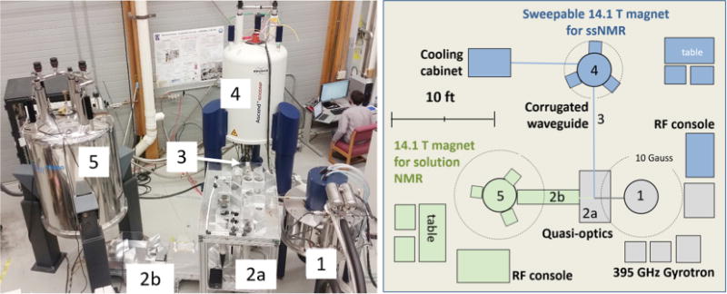
Photograph (left) and schematic (right) of the dual 14.1 T DNP-NMR systems. Components: 395 GHz gyrotron (1), upper quasi-optical table (2a), lower quasi-optical table (2b), corrugated waveguide (3), 14.1 T MAS-DNP magnet (4), and 14.1 T Overhauser DNP magnet (5).
2. Microwave system concept
We designed the microwave propagation system following some of the concepts proposed by Lesurf [26,27] to control the beam (power and polarization), continuously monitor its power, and transmit the microwaves in a nearly loss-free manner. This section describes the design of the microwave handling system, comprised of quasi-optical tables and corrugated waveguides, as well as the characterization of its performance.
Fig. 2 displays schematically the overall concept. Quasi-optical elements (mirrors and polarizating grids) are employed in such a manner that the microwave beam generated by the gyrotron is manipulated via its polarization. The quasi-optical approach provides an extremely efficient means of microwave beam manipulation due to the transmission of microwaves through free-space in a similar fashion to traditional optics. In contrast, waveguides are employed only for beam propagation, albeit with a reduced footprint, allowing transmission in tight spaces such as the bores of superconducting magnets. Here we have designed a microwave handling system which takes advantage of the best properties of both quasi-optics and waveguides without sacrificing flexibility or performance.
Fig. 2.
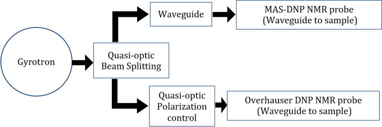
Schematic concept of the single gyrotron supplying microwaves to two DNP-NMR systems. The microwave beam produced by the gyrotron is first split into two components, and each beam is then manipulated and transported to each of the purpose built NMR spectrometers.
3. Microwave components
In this section we describe the components used in the instrument, beginning at the gyrotron and ending at the NMR sample.
3.1. Microwave source: gyrotron
A gyrotron is a high power vacuum tube device [28]. Microwaves are generated by accelerating electrons through a resonant cavity structure located within a strong axial magnetic field, provided in this case by a 7 T cryo-cooled superconducting magnet. The magnetic field causes the electrons to undergo helical trajectories due to the Lorentz force, which induces cyclotron motion perpendicular to the direction of beam propagation. Microwaves are generated via stimulated cyclotron resonance of the electrons within the interaction region, which are then collected by a mode converter [29]. For our DNP applications, the gyrotron operates at the 2nd harmonic of the cyclotron frequency, producing continuous-wave 395 GHz radiation with up to 30 W of output power in the form of a fundamental Gaussian beam mode. The microwaves are then directed through a window into a corrugated waveguide for use in the DNP instruments. In this study, a commercial gyrotron manufactured by CPI and acquired from Bruker Biospin, was utilized.
3.2. Quasi-optical table and mirrors
At the exit of the gyrotron’s waveguide, the microwave beam is transmitted in free space and manipulated via a combination of plane and concave ellipsoidal mirrors [26,27,30], using a breadboard table that allows precise positioning and alignment of all optical elements (see Figs. 1 and 3 for further details). The table is designed such that each mirror is positioned at the diagonal of a square (with 12.5 cm side), perpendicular to the table surface. The concave mirrors have a focal length of 25 cm, and all mirrors are oriented at a 45° angle with respect to the direction of propagation of the microwave beam. The concave ellipsoidal mirrors are used in pairs to correct for distortions that arise from off-axis reflections. Multiple sets of such pairs then allow for periodic refocusing and microwave beam propagation through free space over relatively large distances. Additionally, the breadboard table permits insertion of various microwave components along the propagation axis to control the microwave beam power and polarization.
Fig. 3.
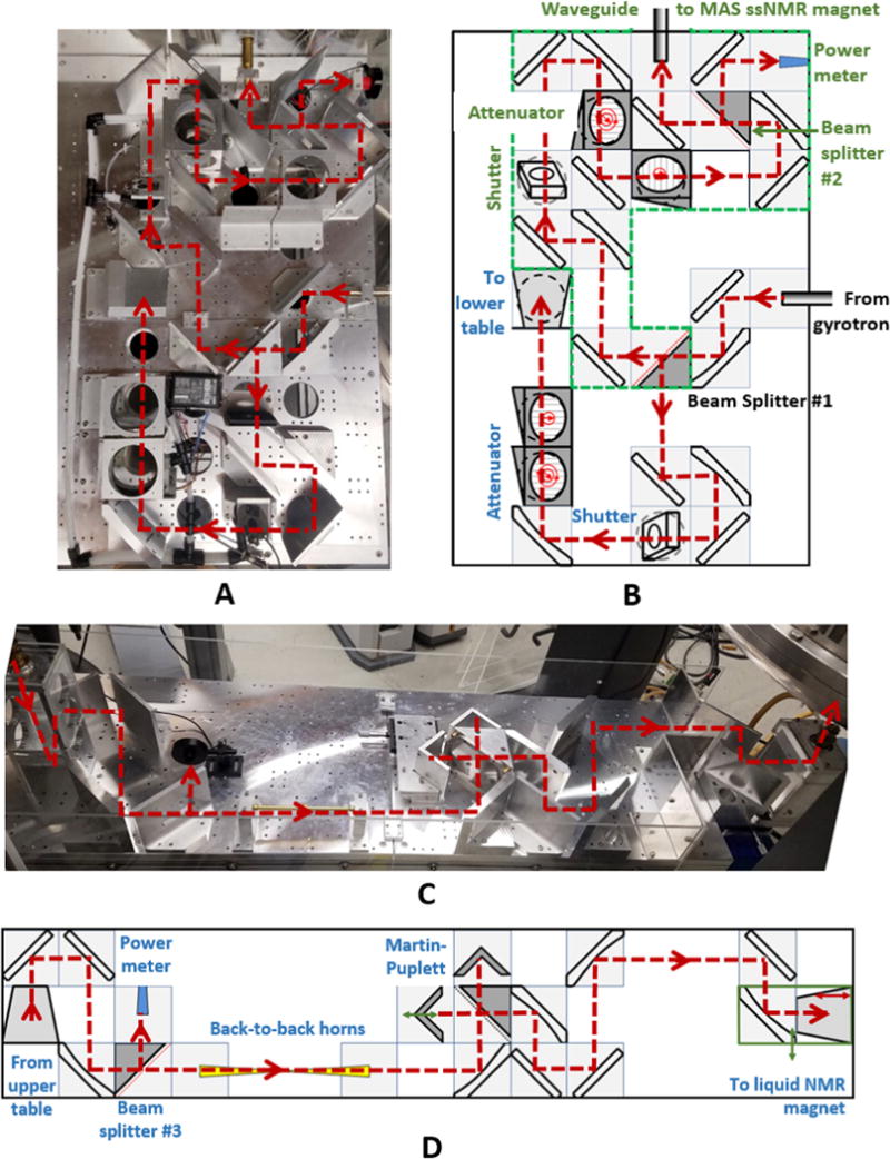
Photographs of the upper (A) and lower (C) quasi-optical tables, together with schematics (B and D, respectively); all components and beam paths are labeled accordingly (see main text for further explanation).
3.3. Wire grids
The wire grids employed in the instrument are made from thin parallel metallic wires stretched across a holder (wires are 10 mm diameter with a spacing of 25 mm, and the grid diameter is 100 mm). Depending on the wire grid orientation, a linearly polarized microwave beam can either reflect from it, transmit through it, or be a combination of the two [31]. Thus, this passive microwave component can be used as a beam splitter. Rotating the grid controls the ratio of transmitted to reflected microwave power (Fig. 4). Both the orientation, θ, of the wires in the grid with respect to the polarization of the microwaves, and the orientation, β, of the plane of the grid holder with respect to the propagation vector of the incident beam, affect the power transmitted and reflected. Here, the grid holders are set at an angle of 45° with respect to the incident beam, such that the reflected portion is 90° from the incident beam. The fractional distribution of power between the transmitted (T) and reflected (R) beams can be written as:
| (1) |
Fig. 4.
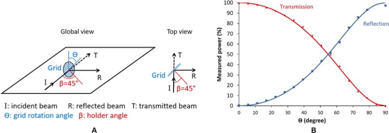
(A) Schematic representation of a wire grid on a quasi-optical table. (B) Measured normalized transmitted and reflected power (data points) as a function of the grid angle, h, with respect to the incident microwave polarization, and a fit to Eq. (1) (solid lines).
In our case, β = 45°. If β was 0°, the transmitted power would simply be proportional to sin2 θ, otherwise known as the Malus law. By rotating the wire grid (i.e. adjusting θ), the ratio of transmitted to reflected microwave power can be controlled (Fig. 4). A pyrometer (Ophir pyrometer 3A-P-THz) in combination with a corrugated horn was employed to measure the microwave power either reflected or transmitted through the grid. The pyrometer was calibrated by comparison with an absorbing water load power meter (provided by Bruker Biospin), and its measurement error was determined as 3%. The gyrotron output power was set to 160 mW to measure the transmitted and reflected microwave power.
3.4. Absorber
In cases where one wants to use only a fraction of the available microwave power, a combination of a grid with an absorber is used. The unwanted microwave power is directed from the grid into an absorbing conical load [32] and converted to heat. To prevent overheating, a stream of air is directed into the conical absorber for cooling: see Fig. 1 (absorbing conical load located below the table).
3.5. Martin-Puplett interferometer
To manipulate the polarization, e.g., from linear to circular, or anything in between, a polarizing Martin-Puplett interferometer [33] has been added to the microwave beam path in the Overhauser DNP NMR system (Fig. 3D). By altering the path length in the interferometer, the transmitted polarization state can be moved on a great circle around the Poincare sphere, giving the user the option to inject vertical linear, horizontal linear, clockwise circular, or counter-clockwise circular polarizations [30,34]. The benefits of polarization control are multiple: by selecting only the circular polarization required for saturating the electron spin transitions, one can reduce the overall power delivered to the typically lossy sample, thereby decreasing NMR sample heating. This, in turn, improves control of the sample temperature. Moreover, reduced power allows for operation at a lower sample temperature, which maximizes the DNP enhancement achievable in MAS NMR experiments. Alternatively, one can use the polarization control simply to vary the useful microwave magnetic field (B1) in the sample.
3.6. Non-polarizing dielectric beam splitter
Wire grids are convenient to generate variable beam splitters when the output polarization direction is not a concern. When using the Martin-Puplett interferometer, the incident beam needs to be vertically or horizontally polarized. The use of a wire grid oriented at an angle different from 0° or 90° would not meet these conditions. A solution involves adding a second grid at either 0° or 90° orientation. The polarization output of the combined grids does meet the requirements of the Martin-Puplett interferometer. However, additional microwave power is diverted into an absorber at the 2nd grid. Thus, in situations where power losses are not acceptable, non-polarizing beam splitters are needed [35]. Dielectric slabs or sheets are the simplest way to create non-polarizing beam splitters. Here we use two different materials for two different applications, as described below.
For the first application, we use a high dielectric material, silicon, which is also transparent in the microwave region of the electromagnetic spectrum. Silicon is the perfect material for such an application since large wafers are readily available in various sizes and specifications, including those with a high dielectric constant. Silicon is known to be a transparent material in the THz region of the electromagnetic spectrum [30]. The linear polarization orientation of the E-field of the microwave beam (called p-polarization) is parallel to the quasi-optical table, allowing a 49/51 split for silicon according to Homes [36]. The microwave power division between the reflected and transmitted beams varies with the angle of incidence, polarization, and wafer specifications. For this application we used the highest resistivity wafer available, i.e., lowest doping, such that it is essentially as transparent as pure silicon. The wafer was manufactured by Siltronic A.G. with the following specifications: 100 mm diameter, 525 μm thick, float zone, orientation 111, n-type with phosphorus dopant, and resistivity between 5000 and 50,000 Ω.cm. When using the silicon wafer as described above, angled at 45° to the incident beam, we obtained a 45/55 ratio for the reflected versus transmitted microwave power. It is important to use thin wafers for such applications to minimize shifts in the optical path, and mis-alignment from the optical axis. A pyrometer (Ophir pyrometer 3A-P-THz) in combination with a corrugated horn was employed to measure the microwave power that was either reflected or transmitted through the silicon wafer. The measurement error of the pyrometer is 3%. The calculated absorption loss of silicon for a 525 μm thick wafer oriented at 45° with respect to the incident beam is just under 2% of the transmitted power. This loss is below the sensitivity limit of the pyrometer used. A loss tangent of 10−3 and an index of refraction of 3.4 was used to calculate the absorption loss [30]. It should be noted that no beam loss was observed using a pyrometer (Ophir pyrometer 3A-P-THz) and, furthermore, no heating of the wafer was observed using a Forward Looking Infra-Red camera (FLIR model E6, with a sensitivity of ±0.06 °C) at 30 W of incident microwave power.
For the second application, a low cost (non-polarizing) beam splitter, made of a thin film of polyethylene (specifically, household plastic wrap), is used to extract a small fraction of the microwave beam which is then directed onto a pyrometer for power measurements. The splitter has a transmission to reflection ratio of about 1000, such that 1 W of incident microwave power results in ~1 mW sent to the pyrometer. This tool enables real-time monitoring of microwave beam powers during NMR experiments. The reflectivity of a thin film of polyethylene should be 0.85% using Fresnel’s law with a p-polarization, index of refraction of 1.5 [30], and a 45° angle of incidence. However, we only observed a value of 0.1%. The difference between the calculated and observed reflectivity cannot be attributed to absorption, since essentially no heat was absorbed by the film due to its very small loss tangent, 3 ×10− 4 [30]. This was confirmed by monitoring the surface temperature of the film with a FLIR camera when up to 30 W of microwave power was allowed to propagate through it. Rather, the large discrepancy in reflectivity is due to destructive interference between the reflections from the front and back surfaces of the thin film. Using the difference between the expected and measured reflectivity one can calculate a 173.2° phase difference between the microwaves reflected from the two surfaces, corresponding to a thickness of 9.5 lm. This is in agreement with the polyethylene thin film manufacturer’s specifications (for example Dow’s Saran® wrap is 12.7 μm thick).
3.7. Shutter
A high speed mechanical shutter (Vincent Associates VS25) in line with the microwave beam path can be remotely operated by the NMR spectrometer. When closed, the shutter diverts the microwave beam into an absorbing load and, when open, allows the beam to pass through unaltered. Two high-speed mechanical shutters have been incorporated, one in each of the two microwave beam paths to the two NMR spectrometers. The shutters can open/close in 3 ms, with a repetition rate up to 33 Hz. The shutters are placed at a 45° angle with respect to the incident microwave beam such that when they are closed their respective beams are reflected down into conical absorbers. The shutters are controlled via a 5 V TTL signal supplied from the NMR consoles. Control of the shutter via the NMR console allows for integration of microwave beam on/off commands into NMR pulse sequences. The shutter opening is 25 mm, angled at 45° with respect of the microwave incident beam. The shutter cross section with respect to the beam is thus elliptical (25 × 17 mm), and is located at a focal point where the microwave beam waist is 10.2 mm. Monitoring of the transmitted beam on a paper screen (using a FLIR camera) demonstrates that it is not affected by passage through the shutter aperture.
3.8. Taper
Tapers are passive microwave components that can be used to change the diameter of a propagating microwave beam. The gyrotron output beam has a 10.2 mm waist (16 mm waveguide internal diameter), which must be reduced to 4.9 mm so that it can be coupled to the narrow waveguide in the Overhauser DNP NMR probes. In order to match these different beam sizes and limit transition losses, a corrugated transition taper was designed and fabricated by Thomas Keating Ltd (the taper flare half-angle is 1°, the input internal diameter is 16 mm and output diameter is 7.67 mm). The taper is essentially lossless, since it employs an HE11 mode with very high coupling efficiency to the Gaussian quasi-optics [37].
3.9. Back-to-back horns
A set of corrugated back-to-back horns were designed and fabricated to serve as a spatial filter for the microwave beam [26]. The horns have input and output internal diameters of 7.67 mm, with a circular taper down to a 1.6 mm internal diameter. These horns collect power from the source side of the quasi-optics and pass it to a single-moded section. Only the fundamental HE11 corrugated mode propagates forward,1 and it is then re-expanded to propagate quasi-optically in free space. The spatial filtering is due to the inability of any higher order HEnm or EHnm (n, m > 1) modes to pass though the fundamental moded section. This ensures that the continuing beam is very well formed, enabling the Martin-Puplett interferometer to generate high quality circularly polarized microwaves.
The Bruker-CPI gyrotron’s output beam is very close to Gaussian, with a fundamental mode content that is greater than 94% according to the manufacturer’s manual. The back-to-back horns function efficiently, with little power loss over and above the filtered component. A power transmission of 91% (−0.4 dB) was measured through the spatial filter using an Ophir 3A-P-THz pyrometer with a measurement error of 3%, confirming the high fundamental Gaussian mode output of the gyrotron. Fig. 5 displays the microwave beam shape before and after filtering. The microwave power distribution was measured by acquiring an infra-red image of the beam via a paper screen placed in the beam propagation path. The gyrotron microwave beam power output was set to 100 mW to avoid burning the paper screen and to prevent signal saturation from the camera sensor. The paper temperature, which was recorded with a FLIR camera, depends on the heat generated by the beam. A slight spatial asymmetry is noticeable before the filter (Fig. 5A), which is corrected by the back-to-back horns (Fig. 5B).
Fig. 5.
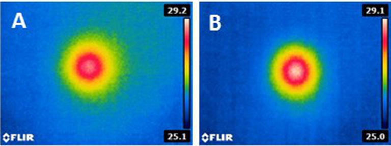
Infrared image of the heat generated by the gyrotron beam on a piece of paper placed transverse to the beam before (A) and after (B) the spatial filter; the color scale is in degrees Celsius. The microwave intensity is highest in the center of the beam and decays radially. However, a slight asymmetry can be seen before the filter (A) – the top right quadrant of the beam is more extended than the bottom left quadrant. After the filter (B), the beam is symmetric. (For interpretation of the references to color in this figure legend, the reader is referred to the web version of this article.)
4. Microwave system
The upper quasi-optical table (2a in Fig. 1) is presented in detail in Fig. 3A & B. It includes components that first split the microwave beam generated by the gyrotron, thus dividing the power between the two DNP instruments. Additional components then allow for power attenuation [38], power measurement, and gating of the two beams. To split the gyrotron output, a non-polarizing beam splitter made from a silicon wafer (beam splitter #1, described above) is used such that 55% of the power is directed to the MAS-DNP instrument. Typically no more than 16 W of microwave power is required to reach the maximum enhancement on the MAS-DNP instrument when the cross effect mechanism is employed at about 110 K. Therefore, since the gyrotron can produce up to 30 W in the fundamental Gaussian mode, this leaves up to 14 W for Overhauser DNP experiments.
The MAS-DNP beam is directed to the NMR probe via a series of concave and flat mirrors and, eventually, a corrugated waveguide. Before reaching the waveguide, the microwave power can be attenuated using grids and a shutter. The grids can be rotated such that only a fraction of the power is transmitted, while the remainder is directed below the support table into conical absorbers. A shutter, controlled by the NMR spectrometer, is also placed in the path of the beam to control sample irradiation on a time scale as short as a few milliseconds. This control allows integration of microwave gating into NMR pulse sequences. Additionally, a non-polarizing beam splitter (#2) is used to divert a very small fraction (1/1000, see Section 3) of the beam onto a pyrometer calibrated to provide a continuous reading of the power going to the MAS-DNP spectrometer. Once adjusted for power and polarization, the microwave beam is transmitted to the MAS-DNP NMR probe via a corrugated waveguide (16 mm diameter, corresponding to a beam waist of 10.2 mm, optimized for 395 GHz transmission). An in-house modified Bruker 1H, 13C, 15N MAS-DNP probe enables NMR measurements for a variety of nuclei, including 2H, 17O, 29Si, and 67Zn.
The remaining ~45% of the gyrotron output beam is directed to the Overhauser DNP instrument along a separate path on the upper table. The power can again be gated via an electronically controlled shutter, triggered from the NMR console (Varian Direct Drive spectrometer), while rotating grids allow for continuous power control. The beam is then directed via a 45° concave mirror into a corrugated taper that reduces the 10.2 mm beam waist (taper input internal diameter of 16 mm) to a 4.9 mm beam waist (taper output internal diameter of 7.67 mm) so that it matches the diameter of the waveguide in the DNP probe. Upon passing through this horn, the beam impinges on another 45° concave mirror, which directs it into the lower quasi-optical table (Fig. 3C & D, also 2b in Fig. 1). The power reaching the lower table is monitored using a non-polarizing beam splitter (#3, Fig. 3D) in combination with a pyrometer. Back-to-back horns are then used to clean up the beam, and a Martin-Puplett interferometer is used to control the polarization of the beam directed into the NMR probe (i.e. circular vs. linear). Finally, the beam is directed into the Overhauser DNP NMR probe waveguide via a 45° flat mirror. The waveguide propagates the microwave beam to the bottom of the NMR sample tube, thus irradiating the sample under study. The sample tube is oriented vertically surrounded by an NMR coil. It should be noted that the microwaves do not interfere with the NMR coil.2
Finally, it should be noted that no ‘‘cross-talk” between the two instruments is observed. That is, no change in the monitored microwave power is observed on the MAS DNP side when the beam polarization or power is adjusted on the Overhauser DNP side. Similarly, MAS DNP microwave power adjustments do not cause any observable changes in the beam on the Overhauser DNP side.
5. DNP enhanced solid state NMR results
To verify efficient microwave transmission to the sample in the MAS-DNP NMR system, NMR spectra with and without microwave irradiation were collected for the model compound alanine, universally labeled with 13C and 15N. The nitroxide biradical AMUPol was used as a polarizing agent. DNP enhancements of ~128 and 90 were observed for 13C (Fig. 6A) and 15N (Fig. 6B) cross polarization experiments, respectively. These enhancement values are typical for this model compound at 600 MHz [11].
Fig. 6.
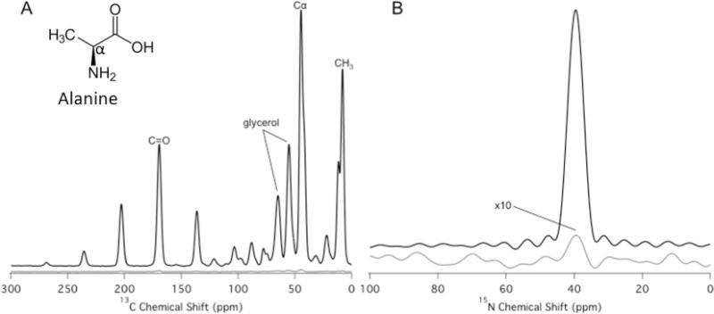
13C (A) and 15N (B) cross polarization spectra with microwaves on (black) and off (grey). The spectra were obtained for a frozen glass containing 0.2 M U-13C, 15N alanine and 10 mM AMUPol dissolved in 60:30:10 glycerol-d8:D2O:H2O. Enhancements of εon/off = 128 (13C) and εon/off = 90 (15N) were obtained. The 15N spectrum with microwaves off is magnified 10 × Resonances at the isotropic chemical shifts of glycerol and the Cα, carbonyl (C=O), and methyl (CH3) groups of alanine are labeled in the 13C spectrum; all other resonances are spinning sidebands. The enhancements were measured by taking the ratio of cross polarization (1H-13C or 1H-15N) signal intensities with and without microwave irradiation. The spectra were collected at a MAS rate of 5 kHz, a cross polarization time of 1.5 ms and a temperature of 110 K.
The buildup of the DNP enhanced signal was measured for the three 13C resonances of alanine (methyl, Ca, and carbonyl) as a function of microwave beam exposure time. These measurements demonstrate the utility of the shutter described in Section 3. The shutter was held open for a variable time, tMW, during the nuclear relaxation delay (see Fig. 7A), and was closed for the remainder of the NMR pulse sequence. A variable delay, tD, before microwave irradiation, was used to keep the timing of the NMR sequence constant. In this way, the DNP enhancement could be recorded as a function of microwave irradiation time, as shown in Fig. 7B. A build up time constant of ~5 s was determined from these measurements. Fig. 8 displays the enhancement for the 13C resonance of urea as a function of microwave power. Full saturation is reached using a microwave power of 17 W, with an enhancement of 131 achieved at a temperature of 110 K and a MAS spinning speed of 8 kHz.
Fig. 7.
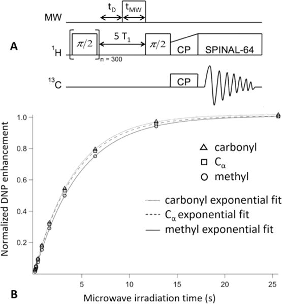
(A) Pulse sequence used to measure the DNP enhancement buildup. The 1H spin bath was first equilibrated by applying 300 π/2 pulses followed by a delay, tD; the shutter was then opened for a variable amount of time, tMW, during the nuclear relaxation delay period, and then closed for the rest of the pulse sequence. A cross polarization scheme was then applied to measure the 13C signal. (B) DNP enhancement of the 13C cross polarization signal as a function of microwave irradiation time. The enhancements were measured by taking the ratio of cross polarization signal intensities (1H-13C) with and without microwave irradiation. The data were collected at a MAS rate of 5 kHz, a cross polarization time of 1.5 ms and a temperature of 110 K.
Fig. 8.
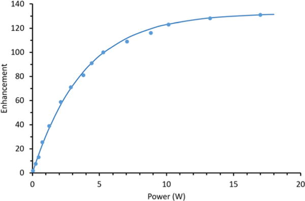
Enhancement for 13C-urea in glycerol-d8/D2O/H2O (6/3/1) containing 10 mM AMUPol, as a function of the microwave power (dots). An exponential fit (solid line) indicates a maximum saturation of 131. The temperature was maintained at 110 K, the cross polarization time was 1 ms and the spinning speed was set at 8 kHz for these experiments.
6. DNP enhanced liquid state NMR
The Overhauser DNP effect is demonstrated here for the first time in a liquid at 14.1 T. An enhancement of 160 is observed for the 31P signal in triphenylphosphine (Fig. 9A), using the BDPA radical (1,3-bis(diphenylene)-2-phenylallyl) in deuterated benzene, with a sample volume of 50 μL (3 mm outer diameter sample tube). This enhancement is essentially the same as the one observed by Loening et al. at 5 T (140 GHz) [7]. The 31P nuclear spin of triphenylphosphine couples to the unpaired electron of BDPA owing to a strong scalar interaction when they form an adduct by making an association in the solution [7]. It has been shown that the scalar Overhauser effect should be field independent [39] but, in practice, competing relaxation mechanisms make the effect field dependent [40]. Here we use 31P in triphenylphosphine as a model compound to demonstrate that an optimized microwave transmission system enables large DNP enhancements for large sample volumes at high magnetic fields.
Fig. 9.
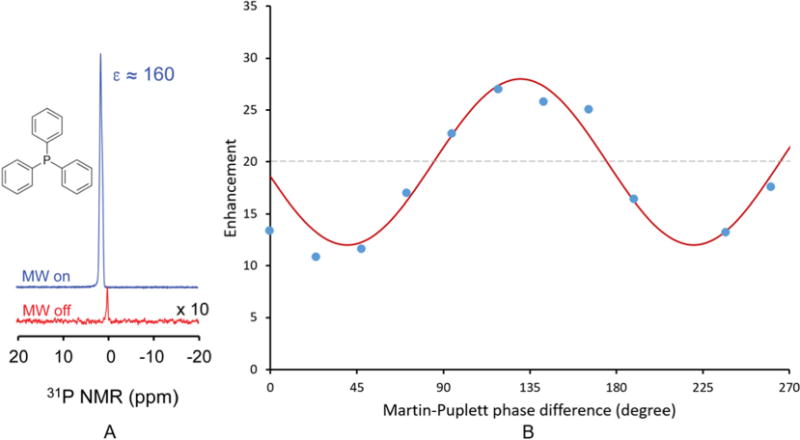
(A) 14.1 T NMR spectra of 31P for triphenylphosphine (850 mM) co-dissolved with the BDPA radical (100 mM) in deuterated benzene at room temperature, with microwaves on (blue) and off (red). The microwave power was set to 2 W at a frequency of 395.18 GHz. The observed enhancement is 160 for a sample volume of 50 μL. (B) 31P enhancement as function of the Martin-Puplett interferometer phase difference (experimental data points in blue and, sine squared fit in solid red); In this case the sample is triphenylphosphine (700 mM) co-dissolved with the galvinoxyl radical (50 mM) in deuterated benzene with a 60 μL sample volume and 2 W of microwave irradiation at room temperature. The simulated curve fits the data when we account for some depolarization of the beam occurring in the NMR probe. Dashed line: expected enhancement for a linearly polarized beam, i.e. equivalent to no Martin-Puplett interferometer regulation of the beam polarization. (For interpretation of the references to color in this figure legend, the reader is referred to the web version of this article.)
Our large sample volume is possible due to the high power microwave output of the gyrotron and the optimized microwave-sample coupling design, while keeping sample heating to a minimum. In the past [15,17,41,42], the lack of power available from microwave sources at high magnetic fields and frequencies resulted in the use of resonant cavities to provide sufficient microwave B1 field to polarize the electron spins. This reliance on resonators has therefore limited the observation of Overhauser DNP in liquids to significantly smaller samples volumes. For example, at a frequency of 260 GHz (corresponding to 9.2 T), a sample volume of 10 nL was irradiated using a 250 mW microwave beam to demonstrate the Overhauser DNP effect [43].
The Overhauser DNP NMR signal enhancement is essentially proportional to a coupling factor, ρ, a leakage factor, f, a saturation factor, s, and the ratio between the gyromagnetic ratios of the electron and nucleus of interest (γe/γn ≈ 1600 for 31P) [17]:
In this case, scalar coupling with 31P gives a positive enhancement. The leakage factor was calculated from measurements of the nuclear T1n, in the presence and absence of radicals, to be about 0.9 which is consistent with previously observed values [41]. Finally the saturation factor is defined as:
where B1 is the magnetic field generated by the microwave beam, and T1e and T2e are the electron relaxation times characteristic of the radical used at the selected magnetic field, temperature and concentration. Organic radical relaxation times are typically in the range of hundreds of nanoseconds and a few tens of nanoseconds for radicals in liquids at room temperature in magnetic fields of 3.4 T [17] and 9.2 T, respectively [44]. At a fixed radical concentration, temperature and field, the saturation coefficient, and, consequently, the Overhauser DNP enhancement varies linearly with microwave power To maximize the saturation coefficient, the microwave beam needs to be circularly polarized with a handedness (clockwise or anti-clockwise) that matches the direction of the B0 field of the NMR magnet. Here we take advantage of the installed Martin-Puplett interferometer to find the microwave polarization which maximizes the saturation coefficient and, therefore, the enhancement. Fig. 9B displays the enhancement obtained for 31P triphenylphosphine mixed with the radical galvinoxyl in deuterated benzene as a function of the Martin-Puplett phase difference, i.e., the polarization state. When the enhancement is at its extremes, the microwaves are polarized circularly, either clockwise or anti-clockwise, leading to an increase or decrease in electron polarization. For an ideal system, the lowest enhancement obtained should be unity (i.e. no electron excitation), while the maximum enhancement for the sample employed in Fig. 9B should be close to forty (i.e. twice the enhancement of the linearly polarized microwave beam). In these measurements, the correct circularly polarized beam gives a 40% increase in enhancement over linear polarization. The microwave power was kept constant throughout these measurements. The discrepancy between this value and the ideal case is attributed to a loss of polarization in the probe. Nonetheless, the polarization optimization is larger than the one observed by Thurber et al. [34], where they found an increase in polarization of about 30% for solid samples using a MAS-DNP instrument at 9.4 T (400 MHz 1H, 263 GHz) with a similar quasi-optical Martin-Puplett interferometer. It should also be noted that the enhancement increases with the polarization orientation as long as one is in the linear regime (as opposed to the saturation regime).
7. Conclusions
A quasi-optical and waveguided microwave beam transport system designed to supply high power microwaves to two independent DNP NMR instruments using a single microwave source, a gyrotron operating at 395 GHz, is presented. The developed system allows independent control of the microwave beam (power and gating) for each instrument as well as full control of the beam polarization for the Overhauser DNP instrument. A MAS-DNP experiment is demonstrated with an enhancement of 128 for a 13C cross polarization spectrum using the model compound alanine with AMUPol as the polarizing agent. An unprecedented Overhauser liquid DNP experiment is demonstrated for the first time at 14.1 T with an enhancement of 160 for a 31P spectrum using the model compound triphenylphosphine with BDPA as the polarizing agent. It should be noted that the 50 μL sample volume, is much larger than those employed up to now in setups that rely on a resonant cavity, demonstrating that, with sufficient microwave power, more conventional NMR sample sizes can be utilized.
There is a clear benefit to developing this hardware: quasioptical transmission lines bring flexibility, gating, and more instrument time by supplying sufficiently high power microwaves to two independent DNP NMR systems at a much lower cost than would be realized by utilizing two separate gyrotrons. Beam shaping and polarizing capabilities enable new DNP approaches that are not possible with traditional DNP NMR systems based on waveguides alone. Future plans involve installation of a quasi-optical table in-lieu of the current waveguide connection to the MAS-DNP NMR probe. This will allow for addition of a Martin-Puplett interferometer for this instrument, thus providing control of the microwave polarization going into the probe. The circularly polarized microwaves should allow the saturation of the electron spins at a lower microwave power, enabling a reduction in microwave heating and a subsequent further increase in the observed enhancements on the MAS-DNP NMR instrument (these enhancements are inversely proportional to temperature in this regime). In addition, we have designed and will install a high sensitivity in-situ EPR spectrometer with a phase coherent (and high dynamic range) source/detector combination. This will allow the detection of EPR spectra for radicals present in the NMR samples, as prepared for DNP experiments and at the field of interest (14.1 T). Finally, various radicals and sample preparations will be tested to demonstrate the Overhauser DNP effect in liquids for large sample volumes via dipolar coupling.
Acknowledgments
The facility development was supported by the National Science Foundation grants CHE-1229170 and the National Institute of Health grant P41 GM122698 and S10 OD108519. A portion of this work was performed at the National High Magnetic Field Laboratory, which is supported by National Science Foundation Cooperative Agreements No. DMR-1644779, DMR-1157490 and the State of Florida. The authors would like to thank Robert Griffin, Melanie Rosay, and Jagadishwar Sirigiri for useful suggestions, David Morris for the design and manufacturing of the sweep coil for the Overhauser DNP instrument, Bailey Trzcinski for the microwave power calibration measurements and Jim Rocca and Malathy Elumalai for their assistance with VnmrJ 4.2 training, software and firmware upgrades.
Footnotes
The use of back-to-back horns as THz spatial mode filters came out of the astronomical community in the 1980’s and has had notable uses in cosmic microwave background anisotropy measurements, most notably the Planck mission [45].
The complete design and performance of the in-house developed Overhauser DNP probe will be presented elsewhere.
References
- 1.Carver TR, Slichter CP. Phys Rev. 1956;102:975–980. [Google Scholar]
- 2.Becerra LR, Gerfen GJ, Temkin RJ, Singel DJ, Griffin RG. Phys Rev Lett. 1993;71:3561–3564. doi: 10.1103/PhysRevLett.71.3561. [DOI] [PubMed] [Google Scholar]
- 3.Thurber KR, Tycko R. J Chem Phys. 2012;137:84508. doi: 10.1063/1.4747449. [DOI] [PMC free article] [PubMed] [Google Scholar]
- 4.Mentink-Vigier F, Akbey Ü, Hovav Y, Vega S, Oschkinat H, Feintuch A. J Magn Reson. 2012;224:13–21. doi: 10.1016/j.jmr.2012.08.013. [DOI] [PubMed] [Google Scholar]
- 5.Mentink-Vigier F, Akbey Ü, Oschkinat H, Vega S, Feintuch A. J Magn Reson. 2015;258:102–120. doi: 10.1016/j.jmr.2015.07.001. [DOI] [PubMed] [Google Scholar]
- 6.Mance D, Gast P, Huber M, Baldus M, Ivanov KL. J Chem Phys. 2015;142:234201. doi: 10.1063/1.4922219. [DOI] [PubMed] [Google Scholar]
- 7.Loening NM, Rosay M, Weis V, Griffin RG. J Am Chem Soc. 2002;124:8808–8809. doi: 10.1021/ja026660g. [DOI] [PubMed] [Google Scholar]
- 8.Dorn HC, Gitti R, Tsai KH, Glass TE. Chem Phys Lett. 1989;155:227–232. [Google Scholar]
- 9.Can TV, Caporini Ma, Mentink-Vigier F, Corzilius B, Walish JJ, Rosay M, Maas WE, Baldus M, Vega S, Swager TM, Griffin RG. J Chem Phys. 2014;141:64202. doi: 10.1063/1.4891866. [DOI] [PMC free article] [PubMed] [Google Scholar]
- 10.Maly T, Debelouchina GT, Bajaj VS, Hu KN, Joo CG, Mak-Jurkauskas ML, Sirigiri JR, van der Wel PCA, Herzfeld J, Temkin RJ, Griffin RG. J Chem Phys. 2008;128:52211. doi: 10.1063/1.2833582. [DOI] [PMC free article] [PubMed] [Google Scholar]
- 11.Sauvée C, Rosay M, Casano G, Aussenac F, Weber RT, Ouari O, Tordo P. Angew Chem Int Ed. 2013;52:10858–10861. doi: 10.1002/anie.201304657. [DOI] [PubMed] [Google Scholar]
- 12.Bennati M, Hardy MI, Karoui H, Lucarini M, Mezzina E, Ouari O, Smirnov AI, Stoll S, Tkach I, Tordo P, Turke M-T, Voinov MA. Electron Paramagnetic Resonance. Royal Soc, RSC Publishing; Cambridge, UK: 2010. [Google Scholar]
- 13.Neugebauer P, Krummenacker JG, Denysenkov VP, Helmling C, Luchinat C, Parigi G, Prisner TF. Phys Chem Chem Phys. 2014;16:18781–18787. doi: 10.1039/c4cp02451f. [DOI] [PubMed] [Google Scholar]
- 14.George C, Chandrakumar N. Angew Chem. 2014;53:8441–8444. doi: 10.1002/anie.201402320. [DOI] [PubMed] [Google Scholar]
- 15.van der Heijden GHA, Kentgens APM, van Bentum PJM. Phys Chem Chem Phys. 2014;16:8493–8502. doi: 10.1039/c3cp55254c. [DOI] [PubMed] [Google Scholar]
- 16.Kryukov EV, Newton ME, Pike KJ, Bolton DR, Kowalczyk RM, Howes AP, Smith ME, Dupree R. Phys Chem Chem Phys. 2010;12:5757. doi: 10.1039/c003189e. [DOI] [PubMed] [Google Scholar]
- 17.Liu G, Levien M, Karschin N, Parigi G, Luchinat C, Bennati M. Nat Chem. 2017;9:676–680. doi: 10.1038/nchem.2723. [DOI] [PubMed] [Google Scholar]
- 18.Lee D, Takahashi H, Thankamony ASL, Dacquin JP, Bardet M, Lafon O, De Paëpe G. J Am Chem Soc. 2012;134:18491–18494. doi: 10.1021/ja307755t. [DOI] [PubMed] [Google Scholar]
- 19.Mathies G, Caporini MA, Michaelis VK, Liu Y, Hu K-N, Mance D, Zweier JL, Rosay M, Baldus M, Griffin RG. Angew Chem. 1940;127(2015):11936–11941. doi: 10.1002/anie.201504292. [DOI] [PMC free article] [PubMed] [Google Scholar]
- 20.Lesage A, Lelli M, Gajan D, Caporini MA, Vitzthum V, Miéville P, Alauzun J, Roussey A, Thieuleux C, Mehdi A, Bodenhausen G, Coperet C, Emsley L. J Am Chem Soc. 2010;132:15459–15461. doi: 10.1021/ja104771z. [DOI] [PubMed] [Google Scholar]
- 21.Akbey U, Franks WT, Linden A, Orwick-Rydmark M, Lange S, Oschkinat H. Top Curr Chem. 2013;338:181–228. doi: 10.1007/128_2013_436. [DOI] [PubMed] [Google Scholar]
- 22.Perras Fa, Kobayashi T, Pruski M. J Am Chem Soc. 2015;137(26):8336–8339. doi: 10.1021/jacs.5b03905. 150622115706000. [DOI] [PubMed] [Google Scholar]
- 23.Thankamony ASL, Wittmann JJ, Kaushik M, Corzilius B. Prog Nucl Magn Reson Spectrosc. 2017 doi: 10.1016/j.pnmrs.2017.06.002. [DOI] [PubMed] [Google Scholar]
- 24.Rosay M, Blank M, Engelke F. J Magn Reson. 2016;264:88–98. doi: 10.1016/j.jmr.2015.12.026. [DOI] [PubMed] [Google Scholar]
- 25.Smith AN, Twahir UT, Dubroca T, Fanucci GE, Long JR. J Phys Chem B. 2016;120(32):7880–7888. doi: 10.1021/acs.jpcb.6b02885. https://doi.org/10.1021/acs.jpcb.6b02885. [DOI] [PMC free article] [PubMed] [Google Scholar]
- 26.Pike KJ, Kemp TF, Takahashi H, Day R, Howes AP, Kryukov EV, MacDonald JF, Collis AEC, Bolton DR, Wylde RJ, Orwick M, Kosuga K, Clark AJ, Idehara T, Watts A, Smith GM, Newton ME, Dupree R, Smith ME. J Magn Reson. 2012;215:1–9. doi: 10.1016/j.jmr.2011.12.006. [DOI] [PubMed] [Google Scholar]
- 27.Lesurf JCG. Millimetre-Wave Optics. CRC Press, Devices and Systems; 1990. [Google Scholar]
- 28.Kartikeyan M, Borie E, Thumm M. Gyrotrons. first. Springer-Verlag; 2004. [Google Scholar]
- 29.Rosay M, Tometich L, Pawsey S, Bader R, Schauwecker R, Blank M, Borchard PM, Cauffman SR, Felch KL, Weber RT, Temkin RJ, Griffin RG, Maas WE. Phys Chem Chem Phys. 2010;12:5850. doi: 10.1039/c003685b. [DOI] [PMC free article] [PubMed] [Google Scholar]
- 30.Goldsmith P. Quasi-Optical Systems. Wiley-IEEE; 1998. [Google Scholar]
- 31.Costley AE, Hursey KH, Neill GF, Ward JM. J Opt Soc Am. 1977;67:979–981. [Google Scholar]
- 32.Murk A, Duric A, Patt F. Proc 19th Int Symp Sp Terahertz Technol. 2008:530–533. [Google Scholar]
- 33.Martin DH, Puplett E. Infrared Phys. 1969;10:105–109. [Google Scholar]
- 34.Thurber KR, Tycko R. J Magn Reson. 2016;264:99–106. doi: 10.1016/j.jmr.2016.01.011. [DOI] [PMC free article] [PubMed] [Google Scholar]
- 35.Woskov PP, Bajaj VS, Hornstein MK, Temkin RJ, Griffin RG. IEEE Trans, Microw Theory Tech. 2005;53:1863–1869. doi: 10.1109/TMTT.2005.848097. [DOI] [PMC free article] [PubMed] [Google Scholar]
- 36.Homes CC, Carr GL, Lobo RPSM, Laveigne JD, Tanner DB. Appl Opt. 2007;46:7884–7888. doi: 10.1364/ao.46.007884. [DOI] [PubMed] [Google Scholar]
- 37.Wylde RJ. IEEE Proc. 1984;131:256–262. [Google Scholar]
- 38.Bogdashov AA, Belousov VI, Chirkov AV, Denisov GG, Korchagin VV, Kornishin SY, Tai EM. J Infrared, Millimeter, Terahertz Waves. 2011;32:823–837. [Google Scholar]
- 39.Overhauser AW. Phys Rev. 1953;92:411–415. [Google Scholar]
- 40.Hausser KH, Stehlik D. Adv Magn Opt Reson. 1968:79–139. [Google Scholar]
- 41.Neugebauer P, Krummenacker JG, Denysenkov VP, Parigi G, Luchinat C, Prisner TF. Phys Chem Chem Phys. 2013;15:6049–6056. doi: 10.1039/c3cp44461a. [DOI] [PubMed] [Google Scholar]
- 42.Torrezan AC, Han Seong-Tae, Mastovsky I, Shapiro MA, Sirigiri JR, Temkin RJ, Barnes AB, Griffin RG. IEEE Trans Plasma Sci. 2010;38:1150–1159. doi: 10.1109/TPS.2010.2046617. [DOI] [PMC free article] [PubMed] [Google Scholar]
- 43.Neugebauer P, Krummenacker JG, Denysenkov VP, Helmling C, Luchinat C, Prisner TF. Phys Chem Chem Phys. 2014;16:18781–18787. doi: 10.1039/c4cp02451f. [DOI] [PubMed] [Google Scholar]
- 44.Krummenacker JG, Denysenkov V, Prisner TF. Appl Magn Reson. 2012;43:1–2. [Google Scholar]
- 45.Murphy JA, Peacocke T, Maffei B, McAuley I, Noviello F, Yurchenko V, Ade PAR, Savini G, Lamarre JM, Brossard J, Colgan R, Gleeson E, Lange AE, Longval Y, Pisano G, Puget JL, Ristorcelli I, Sudiwala R, Wylde RJ. J Instrum. 2010;5:T04001. [Google Scholar]