

Abstract
Organic light‐emitting diodes (OLEDs) are one of the most promising technologies for future displays and lighting. Compared with the blue and green OLEDs that have achieved very high efficiencies by using phosphorescent Ir(III) complexes, the red OLEDs still show relatively low efficiencies because of the lack of high‐performance red‐emitting Ir(III) complexes. Here, three highly efficient asymmetric red‐emitting Ir(III) complexes with two different cyclometalating ligands made by incorporating only one electron‐deficient triarylboron group into the nitrogen heterocyclic ring are reported. These complexes show enhanced photoluminescence quantum yields up to 0.96 and improved electron transporting capacity. In addition, the asymmetric structure can help to improve the solubility of Ir(III) complexes, which is crucial for fabricating OLEDs using the solution method. The photoluminescent and oxidation–reduction properties of these Ir(III) complexes are investigated both experimentally and theoretically. Most importantly, a solution‐processed red OLED achieves extremely high external quantum efficiency, current efficiency, and power efficiency with values of 28.5%, 54.4 cd A−1, and 50.1 lm W−1, respectively, with very low efficiency roll‐off. Additionally, the related device has a significantly extended operating lifetime compared with the reference device. These results demonstrate that the asymmetric diarylboron‐based Ir(III) complexes have great potential for fabricating high‐performance red OLEDs.
Keywords: asymmetric Ir(III) complexes, diarylboron, high efficiency diodes, red phosphor, solution‐processed organic light‐emitting diodes
1. Introduction
Organic light‐emitting diodes (OLEDs) have been regarded as the most promising candidate for both displays and solid‐state lighting sources.1, 2, 3 In the development of OLEDs, the most important issue is the research on emitting materials because they have crucial influence on the emission colors and efficiencies.4, 5 Efficient blue, green, orange, and red‐emitting materials are essential to develop high‐performance OLEDs applied to displays and solid‐state lighting sources. Among all the emitting materials developed for OLEDs, phosphorescent transition metal complexes, e.g., Ir(III) and Pt(II) complexes, have drawn great attention due to their capability of harvesting 100% of the both singlet and triplet excitons electrogenerated in devices.6, 7 Using Ir(III) complexes as emitters, blue, green, and orange OLEDs with external quantum efficiencies (EQEs) over 30% have been reported.8, 9, 10, 11, 12 However, even based on elaborately designed bipolar host materials and sophisticated device structures, only several most efficient vacuum‐deposited red OLEDs using Ir(III) complexes as emitters show EQEs around 26%.11, 13, 14, 15, 16 As for the solution‐processed red OLEDs based on Ir(III) complexes, the highest EQEs are less than 22%.17, 18, 19 Compared with the extremely high efficiencies of blue, green, and orange OLEDs, one of the reasons for the inferior efficiencies of these red OLEDs is the low photoluminescence quantum yields (PLQYs) of the emitter. For example, the PLQYs of the widely used red phosphors bis(2‐methyldibenzo‐[f,h]‐quinoxaline)Ir(III)(acetylacetonate) [(MDQ)2Ir(acac)] and bis(1‐phenylisoquinoline)Ir(III)(acetylacetonate)[(piq)2Ir(acac)] are only 0.48 and 0.2, respectively.20, 21 According to “the energy gap law,”22 as the energy gap between the emissive excited state and the ground state decreases, the nonradiative rate constant (k nr) increases while the radiative rate constant (k r) decreases. Thus, the red emissive materials with narrow energy gaps tend to display low PLQYs.23 However, because the phosphorescence of Ir(III) complexes mainly result from the metal‐to‐ligand charge transfer (MLCT) and ligand‐centered (LC) transitions, the emission properties including the PLQY of an Ir(III) complex are decided by the organic ligands. It means that there is still a chance to improve the photoluminescence quantum yield (PLQY) of an Ir(III) complex by carefully designing the organic ligands.
Recently, we reported a diarylboron‐based red‐emitting Ir(III) complex [bis(5‐(dimesitylboranyl)‐2‐phenylpyridine)Ir(III)(acetylacetonate), Ir‐B‐1] showing high PLQY of 0.95 in CH2Cl2, which is among the highest PLQYs reported for red‐emitting Ir(III) complexes.24 The enhanced PLQY could be attributed to the incorporation of electron‐deficient diarylboron group into the pyridine ring, which could increase the mixing of the MLCT state and the triplet ligand‐centered (3LC) state of the complex.25 Moreover, the electron‐deficient diarylboron group could improve the electron‐transporting ability of the resultant complex.24, 26 Therefore, a conventional vacuum‐deposited OLED using Ir‐B‐1 as emitter could show high EQE of 14.7% with low efficiency roll‐off, which is much better than the control device (EQE = 6.0%) based on (MDQ)2Ir(acac).24 However, Ir‐B‐1 shows relatively poor solubility in common organic solvents, which makes it unsuitable for fabricating OLEDs with solution‐processed method. Considering the advantages of the solution‐processed method in fabricating large‐area and flexible OLEDs via the low‐cost printing method or roll‐to‐roll coating technique,27, 28, 29 it is in urgent demand to develop efficient red Ir(III) complexes for applications in high‐performance solution‐processed red OLEDs. Therefore, following the design experience of Ir‐B‐1, we developed another three diarylboron‐based asymmetric Ir(III) complexes as shown in Scheme 1 . Different from the common structures of heteroleptic Ir(III) complexes such as Ir‐B‐1 in which the two cyclometalating ligands are identical except for the ancillary ligand acetylacetonate (acac), the structures of these three newly synthesized Ir(III) complexes contain two different cyclometalating ligands, i.e., one cyclometalating ligand has a diarylboron group and the other does not. We design these Ir(III) complexes based on the following reason. In addition to the enhancement of the electron‐transporting ability, the incorporation of electron‐deficient diarylboron group into one of the cyclometalating ligands can notably increase the PLQY. The other cyclometalating ligand without diarylboron group can break the symmetric structure of the molecule to improve the solubility. Consequently, these Ir(III) complexes with totally asymmetric structures can show good solubilities in common organic solvents with high PLQYs up to 0.89 in THF. In addition, the PLQY of BPyThIr doped 4,4′,4″‐tri(N‐carbazolyl)triphenylamine (TCTA) film can be increased to 0.96. Most importantly, the solution‐processed red OLED based on BPyThIr shows an extremely high EQE of 28.5%, which is the highest record for the solution‐processed red OLED to date.17, 18, 19 In addition, the operation lifetime of the device using BPyThIr as emitter is significantly improved over 30% compared to the device based on (MDQ)2Ir(acac).
Scheme 1.

Structural drawing of diarylboron‐based asymmetric Ir(III) complexes.
2. Results and Discussion
The syntheses of these diarylboron‐based Ir(III) complexes were similar to the common methods reported for other heteroleptic Ir(III) complexes except the solvents used here were the mixture of THF and H2O rather than the conventional used mixture of 2‐ethoxyethanol and H2O (see the Supporting Information).30 Adopting the one‐pot method, one asymmetrical complex and two symmetric complexes were formed at the same time with acceptable yields. If the two cyclometalating ligands were heated with IrCl3 one after another, isolated yields of the asymmetric complex could be further improved. The NMR and mass spectral investigations confirmed the asymmetric structures (see Figures S1 and S2 in the Supporting Information) of these Ir(III) complexes. Their thermal properties were evaluated by the thermogravimetric analysis. The decomposition temperatures (T d) of these Ir(III) complexes were in the range from 225 to 267 °C (Table 1 and Figure S3, Supporting Information), which are high enough for the device fabrication processes and practical usages.
Table 1.
Photophysical, thermal data, and HOMO/LUMO levels for these diarylboron‐based asymmetric Ir(III) complexes
| Complex | λabs a) [nm] [logε] | λem [nm] THFa)/filmb) | PLQY THFa)/filmb) | τp [µs] THFa)/filmb) | T d [°C] | HOMO/LUMO [eV] |
|---|---|---|---|---|---|---|
| BThThIr | 293 (4.21), 353 (4.17), 427 (3.54), 538 (3.40) | 623/612 | 0.75/0.76 | 1.39/1.82 | 225 | −5.37/−2.96 |
| BPyThIr | 309 (4.40), 342 (4.44), 427 (3.62), 530 (3.53) | 619/602 | 0.89/0.96 | 0.93/0.78 | 262 | −5.26/−2.80 |
| BPyPyIr | 339 (4.57), 432 (3.72), 531 (3.70) | 621/607 | 0.69/0.35 | 0.93/0.73 | 267 | −5.26/−2.81 |
The λabs and λem were measured in THF at a concentration of 10−5 m; the PLQYs were measured in degassed THF solution relative to fac‐[Ir(ppy)3] (PLQY = 0.40); the τp were recorded in degassed THF solution
Measured in Ir(III) complexes doped TCTA films at the doping level of 10 wt%.
Figure 1 a shows the absorption spectra of these diarylboron‐based asymmetric Ir(III) complexes in THF solutions. The strong absorption bands in UV region can be ascribed to the spin‐allow singlet 1π–π* transition of the two different cyclometalating ligands. Specifically, the absorption peaks from 325 to 360 nm can be assigned to the 1π–π* transition of cyclometalating ligands bearing diarylboron group since BPyThIr and BPyPyIr with the same diarylboron substituted cyclometalating ligand show the same absorption profile around 340 nm. The absorption peaks in higher energy region (<325 nm) should be attributed to the 1π–π* transition of cyclometalating ligands without the diarylboron group. The weaker absorption occurring in the visible region can be assigned to the singlet and triplet MLCT transition. The singlet and triplet ligand–ligand charge transfer (LLCT) and LC excited states also contribute to the absorption in the visible region, as confirmed by time‐dependent density functional theory (TD‐DFT) calculations (vide infra). As depicted in Figure 1b and listed in Table 1, these complexes showed red emissions with peaks (λem) around 620 nm in THF solutions. The broad featureless emission profiles in the red region indicate these complexes emit primarily from MLCT states.30 Actually, with the polarity of organic solvents increased, the emission peaks were redshifted, and the emission profiles became broad and structureless (Figure S4, Supporting Information), which is similar to the behaviors of other phosphorescent transition metal complexes.31, 32, 33 The notable solvatochromism of these Ir(III) complexes caused by the differences in the dipole moments between the ground (S0) and the first triplet excited (T1) states indicates strong charge transfer character in their T1 state.31, 32, 33 Meanwhile, the different changes of dipole moment in the excited state versus ground state might also be responsible for the weak emission peak in the range of 500–550 nm for BPyPyIr.31, 33 Anyway, very high PLQYs of these complexes were measured up to 0.89 in THF solutions. Compared with those in THF solutions, the emissions of these complexes in TCTA films show hypsochromic shifts (Figure 1c), which are induced by the restricted dipole–dipole relaxation in the rigid matrix, implying the charge redistribution characters between the excited and ground states.34 More importantly, the doped TCTA films also showed very high PLQYs, among which the BPyThIr doped film could show PLQY up to 0.96. It was interesting that the differences of PLQYs between these Ir(III) complexes in films were much greater than in THF solutions. Therefore, we turn our attention to the morphology of TCTA films doped with these Ir(III) complexes. The atomic force microscope (AFM) test results revealed that the BPyThIr‐based film showed a small surface roughness with the root mean square (Sq) value of 1.69 nm (Figure S5, Supporting Information). In comparison, the BPyPyIr‐based film displayed a large Sq up to 3.40 nm. Unlike the case of the BPyThIr‐based film, there existed obviously discontinuous regions in the BPyPyIr‐based film, indicating the emitter aggregation induced phase separation to some extent. Therefore, the AFM images implied that the emitter aggregation behavior was more severe in the BPyPyIr‐based film, which might cause triplet–triplet annihilation effect, leading to the lowest PLQY of the BPyPyIr‐based film. On the whole, the incorporation of diarylboron moieties has greatly influenced the emission properties of these Ir(III) complexes. Remarkable emission redshifts of these diarylboron‐based asymmetric Ir(III) complexes with significantly improved PLQYs have been observed, since the related symmetric Ir(III) complexes without the diarylboron substituent usually show green or green‐yellow emissions with PLQYs less than 0.4.35, 36 In detail, when introducing the diarylboron unit to the thiazole ring, the resulted complex BThThIr displayed longer emission wavelength both in the THF solution and TCTA film, and also its emission lifetimes (τp) were the longest (Table 1 and Figure S6, Supporting Information). With the diarylboron unit attached on the pyridine ring, BPyThIr exhibited the improved PLQY with reduced τp compared with BThThIr. Replacing the 2‐phenylthizole ligand in BPyThIr with the 2‐phenylpyridine ligand reduced the PLQYs of BPyPyIr both in THF solution and TCTA film. These observations demonstrate that the diarylboron unit substituted ligands have dominated effect on the emission properties, while the ligand without diarylboron unit can fine tune the emission wavelengths and PLQYs. Anyhow, the very high PLQYs endow these diarylboron‐based asymmetric Ir(III) complexes with the great potential to fabricate high‐performance red OLEDs.
Figure 1.

a) Absorption and b) emission spectra of these asymmetric Ir(III) complexes recorded in THF; c) emission spectra of doped TCTA film at the 10 wt% doping level.
As shown in Figure 2 , during the cyclic voltammetric scan in CH3CN solutions, these Ir(III) complexes could show reversible metal‐related oxidation waves and reversible diarylboron‐related reduction waves. Interestingly, BPyThIr and BPyPyIr displayed similar oxidation and reduction behaviors, indicating that they possess similar highest occupied molecular orbital (HOMO)/lowest unoccupied molecular orbital (LUMO) levels (Table 1). Given the fact that BPyThIr and BPyPyIr contain the same diarylboron substituted cyclometalating ligand, this result implies that the diarylboron substituted cyclometalating ligand exerts dominated influence on the HOMO/LUMO of these complexes. Therefore, with the diarylboron group attached on the thiazole unit, BThThIr indeed showed different oxidation and reduction behaviors in CH3CN solution compared with BPyThIr, i.e., both the HOMO/LUMO levels of BThThIr (−5.37/−2.96 eV) were lower than those of BPyThIr (−5.26/−2.80 eV). Compared with the symmetric Ir(III) complex Ir‐B‐1 (HOMO/LUMO levels: −5.22/−2.60 eV), the asymmetric Ir(III) complex BPyPyIr shows a similar HOMO level of −5.26 eV but a much deeper LUMO level of −2.81 eV. This may be caused by the fact that a competition in the MLCT process (from the Ir center to the diarylboron moiety) exists in the symmetric Ir(III) complex Ir‐B‐1 between the two diarylboron substituted cyclometalating ligands, but this competition is almost absent in BPyPyIr. Due to the asymmetric structure, the only one diarylboron substituted cyclometalating ligand in BPyPyIr will be the sole destination to accept the electron transferred from the Ir center, making BPyPyIr easier to be reduced. Therefore, one of the advantages by designing the diarylboron‐based asymmetric Ir(III) complexes is to further lower the LUMO levels, which is beneficial to the electron‐injection/transporting process in OLEDs.25, 37
Figure 2.
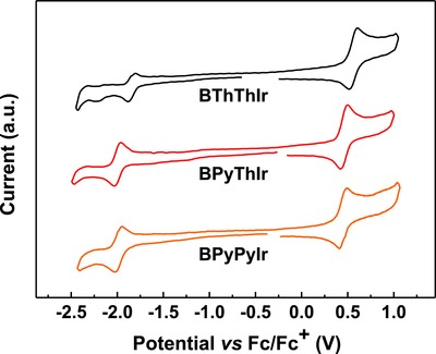
Cyclic voltammogram of these diarylboron‐based asymmetric Ir(III) complexes.
To gain insight into these photophysical and electrochemical properties, we performed the DFT and TD‐DFT calculations. The calculated phosphorescent emission peaks for BThThIr, BPyThIr, and BPyPyIr (λem cal. = 634, 590, 599 nm, respectively) are in good agreement with the trend of the experimentally observed peaks (λem = 612, 602, 607 nm, respectively, for BThThIr, BPyThIr, and BPyPyIr in doped films). As shown in Figure 3 and Figure S7 (Supporting Information), besides the almost equally contribution from the chelated phenyl fragments of the cyclometalating ligand with and without diarylboron group (15.1–17.1% and 14.9–17.0%, respectively) to the HOMOs of BThThIr, BPyThIr, and BPyPyIr, the dπ orbitals of the Ir center in asymmetric Ir(III) complexes make significant contribution (51.4–52.5%) to the HOMOs of these complexes. The LUMOs of these Ir(III) complexes show predominant (more than 92%) distribution over the diarylboron substituted cyclometalating ligand. Specifically, the LUMOs consist of a considerable contribution from the boron atoms (14.5–19.5%). As listed in Table 2 , due to large contributions (86.0–97.6%) from HOMO→LUMO transition to both the lowest singlet transition (S0→S1) and the lowest triplet transition (S0→T1), all the S0→T1 transition for these complexes can be assigned to an MLCT character mixed with some contribution from LLCT and ππ* features. These assignments can also be confirmed by the charge density difference for both S1 and T1 excited states of these Ir(III) complexes (Figure S8, Supporting Information). Therefore, it is reasonable that the diarylboron substituted cyclometalating ligand shows dominant influence on the molecular orbitals, and thereby on the photophysical and electrochemical properties of these complexes.
Figure 3.

Contour plots of HOMO (bottom) and LUMO (top) of these diarylboron‐based asymmetric Ir(III) complexes.
Table 2.
Theoretical calculation results for these diarylboron‐based asymmetric Ir(III) complexes
| Complexa) | State | λcal [nm] | f | Composition | Assignments |
|---|---|---|---|---|---|
| BThThIr |
S1
T1 |
565 634 |
0.0790 |
H→L [97.6%] H→L [86.0%] |
MLCT/LLCT/ππ* MLCT/LLCT/ππ* |
| BPyThIr |
S1
T1 |
544 590 |
0.0659 |
H→L [97.1%] H→L [91.7%] |
MLCT/LLCT/ππ* MLCT/LLCT/ππ* |
| BPyPyIr |
S1
T1 |
552 599 |
0.0602 |
H→L [97.5%] H→L [92.4%] |
MLCT/LLCT/ππ* MLCT/LLCT/ππ* |
H→L represents the HOMO to LUMO transition. f stands for oscillator strength.
Considering the high PLQYs and good solubility of these complexes, solution‐processed OLEDs were fabricated with the conventional structure of indium tin oxide (ITO)/PEDOT:PSS (45 nm)/x wt% Ir emitter:TCTA (30 nm)/TPBI (45 nm)/LiF (1 nm)/Al (100 nm) (Figure S9, Supporting Information). We used poly(ethylenedioxythiophene):poly(styrenesulfonate) (PEDOT:PSS) to inject and transport holes to the emissive layer. The emissive layer consisted of the host TCTA and these Ir(III) complexes. We also used 1,3,5‐tris(N‐phenylbenzimidazole‐2‐yl)benzene (TPBI) as the electron‐transporting layer, and LiF as the electron‐injection layer. Only the doping level was optimized to excavate the electroluminescence (EL) potential of these Ir(III) complexes (i.e., 6, 10, and 14 wt% of BThThIr, BPyThIr, and BPyPyIr in TCTA for devices A1‐3, B1‐3, and C1‐3, respectively). The detailed energy levels and the molecular structures of the materials used in the fabricated OLEDs are shown in Figure S9 (Supporting Information). All these devices displayed red emissions with EL profiles similar to the corresponding PL spectra in doped TCTA films, and no emission from TCTA (≈390 nm) was detected, indicating the complete energy transfer from the host to the emitter. Among these devices, the devices with 10 wt% doped complexes showed the best performances. Their EL spectra, current density(J)–voltage(V)–luminance (L) curves, and efficiencies versus luminance plots are depicted in Figure 4 . The detailed EL data are summarized in Table 3 . The performance of other devices is given in the Supporting Information (Figures S10 and S11 and Table S1, Supporting Information). As listed in Table 3, device A2 based on BThThIr showed a turn‐on voltage of 3.5 V with the maximum luminance (L max), EQE, current efficiency (CE), and power efficiency (PE) of 27 756 cd m−2, 17.5%, 27.4 cd A−1, and 24.9 lm W−1, respectively, which have already outperformed the efficiencies of the vacuum‐deposited device based on the symmetric Ir(III) complex Ir‐B‐1 (14.7%, 21.4 cd A−1, and 22.2 lm W−1).24 Unexpectedly, device B2 based on BPyThIr exhibited extremely high peak EQE, CE, and PE of 28.5%, 54.4 cd A−1, and 50.1 lm W−1, respectively, which outstandingly represents for the highest efficiencies for Ir(III) complex‐based red OLEDs fabricated using solution‐processed or vacuum‐deposited method.11, 13, 14, 15, 16, 17, 18, 19 The remarkable electroluminescent performance of BPyThIr could be attributed to the suitable HOMO/LUMO levels, very high PLQY ( = 0.96) as well as good film morphology (Sq = 1.69 nm) of doped TCTA film. Besides, the transporting behaviors of these Ir(III) complexes were investigated by fabricating hole and electron‐only devices with structures of ITO/MoO3 (3 nm)/PEDOT:PSS (20 nm)/Ir(III) complex (40 nm)/PEDOT:PSS (20 nm)/MoO3 (3 nm)/Al (100 nm) and ITO/LiF (3 nm)/Ir(III) complex (40 nm)/LiF (3 nm)/Al (100 nm), respectively. As shown in Figure 5 , under the same driving voltage, the current densities of holy‐only devices are in the order of BThThIr > BPyThIr > BPyPyIr, suggesting that the hole transporting ability of BPyThIr is in the middle among that of these three Ir(III) complexes. However, the much higher current density of the electron‐only device based on BPyThIr than the other two indicates that BPyThIr can show better electron transporting ability, leading to more balanced hole and electron transporting characteristics within the device. Therefore, the more balanced charge transporting ability of BPyThIr should also make significant contribution to improve the device efficiencies.38 Furthermore, even at high luminance of 1000 cd m−2, the EQE and CE of device B2 still remained as high as 26.7% and 50.9 cd A−1, respectively. It should be noted that this extraordinary device performance was achieved with a conventional device structure using the common unipolar host TCTA. This implies that BPyThIr has the great potential for practical application in developing more efficient red OLEDs with optimized host materials and device structures. Importantly, the device can be conveniently fabricated using the low‐cost solution‐processed method. Because of similar energy levels of BPyPyIr to those of BPyThIr (Table 1), the EL profile and turn‐on voltage of device C2 were similar to those of device B2. However, due to the low PLQY (=0.35), very poor film quality (Sq = 3.40 nm) of BPyPyIr doped TCTA film, as well as the unbalanced charge transporting properties of BPyPyIr, device C2 displayed inferior performance with peak EQE, CE, and PE of 11.3%, 22.0 cd A−1, and 18.8 lm W−1, respectively. Nevertheless, device C2 showed very low efficiency roll‐off even at high luminance of 1000 cd m−2.
Figure 4.

EL characteristics of OLEDs based on BThThIr, BPyThIr, and BPyPyIr: a) EL spectra, b) J–V–L characteristics, c) curves of EQE versus luminance, and d) curves of CE and PE versus luminance.
Table 3.
EL data for devices A2, B2, and C2
| Emitter | λEL max [nm] | Va) [V] | L max [cd m−2] | EQEb) [%] | CEb) [cd A−1] | PEb) [lm W−1] | CIE (x, y) | |
|---|---|---|---|---|---|---|---|---|
| A2 | BThThIr (10 wt%) | 612 | 3.5/7.8/12.3 | 27756 | 17.5/16.1 | 27.4/25.2 | 24.9/10.1 | (0.62, 0.38) |
| B2 | BPyThIr (10 wt%) | 604 | 3.4/7.1/9.8 | 59154 | 28.5/26.7 | 54.4/50.9 | 50.1/23.0 | (0.61, 0.39) |
| C2 | BPyPyIr (10 wt%) | 604 | 3.3/8.4/12.8 | 33659 | 11.3/10.6 | 22.0/20.6 | 18.8/7.0 | (0.60, 0.40) |
Driving voltages (V) in the order of at 1, 1000, and 10 000 cd m−2, respectively
EQE, CE, and PE in the order of the maximum value and at 1000 cd m−2.
Figure 5.
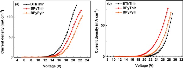
The current density–voltage (J–V) curves for a) hole‐only and b) electron‐only devices based on these complexes.
The operation stability of the unsealed devices based on these diarylboron‐based asymmetric Ir(III) complexes was tested under the N2 atmosphere. For comparison, a control device based on (MDQ)2Ir(acac) was also fabricated with the same device structure. Figure 6 shows the relative luminance versus time for these devices operated with the initial luminance (L 0) of 1000 cd m−2. The operation lifetime value at 50% initial luminance, LT50, for the control device based on (MDQ)2Ir(acac) is about 1500 h, while the LT50 for devices based on our newly synthesized Ir(III) complexes is over 1500 h. Especially, the LT50 for the device based on BPyThIr is about 2000 h, indicating the much higher device stability of using BPyThIr as the emitter than using the widely used (MDQ)2Ir(acac).
Figure 6.
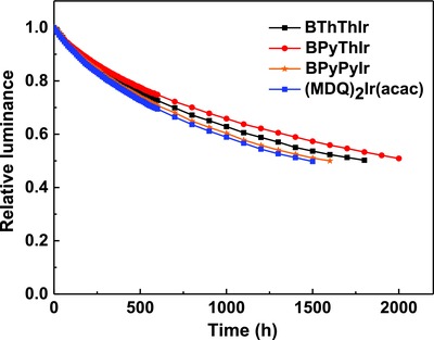
The operating lifetimes for OLEDs based on BThThIr, BPyThIr, BPyPyIr, and (MDQ)2Ir(acac).
3. Conclusion
In summary, we report three red‐emitting asymmetric Ir(III) complexes and demonstrate that the introduction of the diarylboron group into one of the cyclometalating ligands can also significantly improve the PLQYs and lower the LUMO levels of the resultant Ir(III) complexes, which are beneficial to the EL performance. Most importantly, the solution‐processed red OLED using the common unipolar host TCTA and the emitter BPyThIr can achieve extremely high peak EQE, CE, and PE of 28.5%, 54.4 cd A−1, and 50.1 lm W−1, respectively, with very low efficiency roll‐off even at high luminance of 1000 cd m−2. In addition, the lifetime value at 50% initial luminance for the device based on BPyThIr is about 2000 h. These results represent one of the best performances for Ir(III) complex‐based red OLEDs reported so far, indicating that BPyThIr is very promising for practical application in red OLEDs. This work shows the great potential to design diarylboron‐based Ir(III) complexes with an asymmetric molecular structure for highly efficient OLEDs.
Conflict of Interest
The authors declare no conflict of interest.
Supporting information
Supplementary
Acknowledgements
The authors gratefully acknowledge the financial support from the National Natural Science Foundation of China (Grant Nos. 21602170 and 21572176), the Natural Science Foundation of Shaanxi Province (Grant No. 2016JQ2011), the China Postdoctoral Science Foundation (Grant Nos. 2015M580831 and 20130201110034), the Fundamental Research Funds for the Central Universities (Grant Nos. xjj2016061 and cxtd2015003), and the Creative Scientific Research Team in Yulin City.
Yang X. L., Guo H. R., Liu B. A., Zhao J., Zhou G. J., Wu Z. X., Wong W.‐Y., Adv. Sci. 2018, 5, 1701067 https://doi.org/10.1002/advs.201701067
Contributor Information
Guijiang Zhou, Email: zhougj@mail.xjtu.edu.cn.
Zhaoxin Wu, Email: zhaoxinwu@mail.xjtu.edu.cn.
Wai‐Yeung Wong, Email: wai-yeung.wong@polyu.edu.hk.
References
- 1. Kamtekar K. T., Monkman A. P., Bryce M. R., Adv. Mater. 2010, 22, 572. [DOI] [PubMed] [Google Scholar]
- 2. Reineke S., Lindner F., Schwartz G., Seidler N., Walzer K., Lüssem B., Leo K., Nature 2009, 459, 234. [DOI] [PubMed] [Google Scholar]
- 3. Sasabe H., Kido J., J. Mater. Chem. C 2013, 1, 1699. [Google Scholar]
- 4. Fan C., Yang C., Chem. Soc. Rev. 2014, 43, 6439. [DOI] [PubMed] [Google Scholar]
- 5. Yang X., Zhou G., Wong W.‐Y., Chem. Soc. Rev. 2015, 44, 8484. [DOI] [PubMed] [Google Scholar]
- 6. Baldo M. A., O'Brien D. F., You Y., Shoustikov A., Sibley S., Thompson M. E., Forrest S. R., Nature 1998, 395, 151. [Google Scholar]
- 7. Adachi C., Baldo M. A., Thompson M. E., Forrest S. R., J. Appl. Phys. 2001, 90, 5048. [Google Scholar]
- 8. Udagawa K., Sasabe H., Cai C., Kido J., Adv. Mater. 2014, 26, 5062. [DOI] [PubMed] [Google Scholar]
- 9. Shin H., Lee J.‐H., Moon C.‐K., Huh J.‐S., Sim B., Kim J.‐J., Adv. Mater. 2016, 28, 4920. [DOI] [PubMed] [Google Scholar]
- 10. Kim K.‐H., Moon C.‐K., Lee J.‐H., Kim S.‐Y., Kim J.‐J., Adv. Mater. 2014, 26, 3844. [DOI] [PubMed] [Google Scholar]
- 11. Kuei C.‐Y., Tsai W.‐L., Tong B., Jiao M., Lee W.‐K., Chi Y., Wu C.‐C., Liu S.‐H., Lee G.‐H., Chou P.‐T., Adv. Mater. 2016, 28, 2795. [DOI] [PubMed] [Google Scholar]
- 12. Lee S., Shin H., Kim J.‐J., Adv. Mater. 2014, 26, 5864. [DOI] [PubMed] [Google Scholar]
- 13. Fan C. H., Sun P., Su T. H., Cheng C. H., Adv. Mater. 2011, 23, 2981. [DOI] [PubMed] [Google Scholar]
- 14. Feng Y., Li P., Zhuang X., Ye K., Peng T., Liu Y., Wang Y., Chem. Commun. 2015, 51, 12544. [DOI] [PubMed] [Google Scholar]
- 15. Lai C.‐C., Huang M.‐J., Chou H.‐H., Liao C.‐Y., Rajamalli P., Cheng C.‐H., Adv. Funct. Mater. 2015, 25, 5548. [Google Scholar]
- 16. Liu X.‐Y., Liang F., Yuan Y., Cui L.‐S., Jiang Z.‐Q., Liao L.‐S., Chem. Commun. 2016, 52, 8149. [DOI] [PubMed] [Google Scholar]
- 17. Giridhar T., Han T.‐H., Cho W., Saravanan C., Lee T.‐W., Jin S.‐H., Chem. Eur. J. 2014, 20, 8260. [DOI] [PubMed] [Google Scholar]
- 18. Giridhar T., Saravanan C., Cho W., Park Y. G., Lee J. Y., Jin S.‐H., Chem. Commun. 2014, 50, 4000. [DOI] [PubMed] [Google Scholar]
- 19. Liu X., Yao B., Zhang Z., Zhao X., Zhang B., Wong W.‐Y., Cheng Y., Xie Z., J. Mater. Chem. C 2016, 4, 5787. [Google Scholar]
- 20. Duan J. P., Sun P. P., Cheng C. H., Adv. Mater. 2003, 15, 224. [Google Scholar]
- 21. Su Y. J., Huang H. L., Li C. L., Chien C. H., Tao Y. T., Chou P. T., Datta S., Liu R. S., Adv. Mater. 2003, 15, 884. [Google Scholar]
- 22. Caspar J. V., Kober E. M., Sullivan B. P., Meyer T. J., J. Am. Chem. Soc. 1982, 104, 630. [Google Scholar]
- 23. Ho C. L., Li H., Wong W. Y., J. Organomet. Chem. 2014, 751, 261. [Google Scholar]
- 24. Yang X., Sun N., Dang J., Huang Z., Yao C., Xu X., Ho C.‐L., Zhou G., Ma D., Zhao X., Wong W.‐Y., J. Mater. Chem. C 2013, 1, 3317. [Google Scholar]
- 25. Wang X., Chang Y.‐L., Lu J.‐S., Zhang T., Lu Z.‐H., Wang S., Adv. Funct. Mater. 2014, 24, 1911. [Google Scholar]
- 26. Hudson Z. M., Wang S., Dalton Trans. 2011, 40, 7805. [DOI] [PubMed] [Google Scholar]
- 27. Xu H., Chen R., Sun Q., Lai W., Su Q., Huang W., Liu X., Chem. Soc. Rev. 2014, 43, 3259. [DOI] [PubMed] [Google Scholar]
- 28. Han F., Zhang X., Zhang J., Wei Y., Zhang X., Huang W., Xu H., Chem. Commun. 2016, 52, 5183. [DOI] [PubMed] [Google Scholar]
- 29. Cai J.‐X., Ye T.‐L., Fan X.‐F., Han C.‐M., Xu H., Wang L.‐L., Ma D.‐G., Lin Y., Yan P.‐F., J. Mater. Chem. 2011, 21, 15405. [Google Scholar]
- 30. Lamansky S., Djurovich P., Murphy D., Abdel‐Razzaq F., Lee H. E., Adachi C., Burrows P. E., Forrest S. R., Thompson M. E., J. Am. Chem. Soc. 2001, 123, 4304. [DOI] [PubMed] [Google Scholar]
- 31. Wilde A., Watts R. J., J. Phys. Chem. 1991, 95, 622. [Google Scholar]
- 32. Yu J.‐K., Cheng Y.‐M., Hu Y.‐H., Chou P.‐T., Chen Y.‐L., Lee S.‐W., Chi Y., J. Phys. Chem. B 2004, 108, 19908. [Google Scholar]
- 33. Liao K.‐Y., Hsu C.‐W., Chi Y., Hsu M.‐K., Wu S.‐W., Chang C.‐H., Liu S.‐H., Lee G.‐H., Chou P.‐T., Hu Y., Inorg. Chem. 2015, 54, 4029. [DOI] [PubMed] [Google Scholar]
- 34. You Y., Kim K. S., Ahn T. K., Kim D., Park S. Y., J. Phys. Chem. C 2007, 111, 4052. [Google Scholar]
- 35. Lamansky S., Djurovich P., Murphy D., Abdel‐Razzaq F., Kwong R., Tsyba I., Bortz M., Mui B., Bau R., Thompson M. E., Inorg. Chem. 2001, 40, 1704. [DOI] [PubMed] [Google Scholar]
- 36. Yao C., Jiao B., Yang X., Xu X., Dang J., Zhou G., Wu Z., Lv X., Zeng Y., Wong W. Y., Eur. J. Inorg. Chem. 2013, 2013, 4754. [Google Scholar]
- 37. Hudson Z. M., Sun C., Helander M. G., Amarne H., Lu Z. H., Wang S. N., Adv. Funct. Mater. 2010, 20, 3426. [Google Scholar]
- 38. Liu B., Nie H., Zhou X., Hu S., Luo D., Gao D., Zou J., Xu M., Wang L., Zhao Z., Adv. Funct. Mater. 2016, 26, 776. [Google Scholar]
Associated Data
This section collects any data citations, data availability statements, or supplementary materials included in this article.
Supplementary Materials
Supplementary