Abstract
A new kind of hydrophobic and oil sorbent based on jute fiber was successfully prepared by the integration of silica onto a fiber surface via the sol-gel method and subsequent hydrophobic modification with octadecyltrichlorosilane (OTS). Compared with the hydrophilic raw fiber, the modified fiber had a water contact angle (CA) of 136.2°, suggesting that the material has good hydrophobicity. Furthermore, the ability of oil in the oil/water system (taking diesel for example) to absorb was revealed by the kinetics, the isotherm equation, and the thermodynamic parameters. Adsorption behavior was kinetically investigated using pseudo first-order and pseudo second-order models. The data mostly correlated with the pseudo first-order model. The equilibrium adsorption at 298 K was assessed by using the Langmuir and Freundlich isotherm models. The Freundlich model had greater consistency with the experimental data. The obtained thermodynamic parameters demonstrate that the adsorption of diesel is spontaneous, favorable, and exothermic.
Keywords: jute fiber, oil spill, the sol-gel method, hydrophobic, adsorption kinetics
1. Introduction
Oil spills are one of the most seriously threats to the oceans. The commonly used methods for recovery of oil in such spills are the oil containment boom and linoleum methods. However, these oil recovery methods leave a thin layer of oil floating on the surface of the sea. Processes occurring with the disappearance of this layer such as drifting, diffusion, evaporation, emulsification, and sedimentation [1], severely contaminate the ocean and the surrounding environment.
Because of its low cost and high efficiency, an adsorption method is an effective way of removing oil from the ocean surface. A number of oil-absorbing materials for this method, such as natural inorganic materials [2], natural organic materials [3], and composite materials [4], have been applied to clean up oil spills. Natural organic materials such as wood chips [5,6], sugarcane bagasse [7] cotton [8,9], and jute fiber have been used because of their biodegradability. Jute fiber, a lignocellulosic natural fiber mainly composed of cellulose, hemicellulose (82%–85%), and lignin [10,11], has been developed as an adsorbent material by a number of researchers because of its low cost, durability, and eco-friendly properties. Many studies have been carried out to determine the adsorption performance of jute. For example, Gao et al. used jute modified with pyromellitic dianhydride to adsorb aniline in wastewater and obtained significant results [12]. Moreover, Arfaoui et al. attached ZnO nanorods to jute surfaces and then used fatty acids with a contact angle (CA) as large as 148° to conduct superhydrophobic treatment [13]. Most recently, Dong et al. inserted laccase into dodecyl gallate (CA of 111.5°) to modify a jute/polypropylene composite. The rupture strength increased with the assistance of a joint laccase branch; it thus met the requirements of compatibility with hydrophobic resins for producing high-performance fiber composites [14]. All of these studies show that modified jute fiber is an effective absorbing material and that it has potential use in oil-spill cleaning. However, little information is available in terms of the applications of modified jute fiber in ocean oil adsorption.
The main aim of this paper is to propose a preparation method for an environment-friendly oil sorbent that can be practically applied in the removal and recovery of oil spills on water surfaces. The objectives of this study were as follows: (1) to prepare and characterize modified jute fiber, including changes in surface structure and functional groups; (2) to measure the adsorption capacities of raw and modified fiber in pure water and oil systems; and (3) to interpret the kinetics, isotherms, and thermodynamics of diesel adsorption on the modified fiber.
2. Materials and Methods
2.1. Materials
Jute fiber from Hunan, China, was used as a main raw material. Octadecyltrichlorosilane (OTS, analytical grade) was purchased from Beijing McLean Reagent Ltd., China. Ethyl orthosilicate (TEOS, analytical grade) was obtained from Tianjin Xingfu Fine Chemical Research Institute, China. Glacial acetic acid, sodium hydroxide, anhydrous ethanol, ammonia, and hydrochloric acid (analytical grade) were supplied by Tianjin Wind Boat Chemical Reagent Technology Co. Ltd., Tianjin, China. Crude oil was from the Tianjin Water Transport Engineering Research Institute. Lubricating oil and peanut oil were purchased from a local market in Tianjin, China. The oil used for the experiment was a light diesel oil with a kinetic viscosity of 1.8 m2/s and a density of 0.82 g/cm3. It contains paraffins, naphthenes, and aromatic hydrocarbons of 9–18 carbon atoms.
2.2. Modification Method
2.2.1. Pretreatment of the Jute Fiber
The raw materials were pulverized by a grinder, and then 20 to 40 mesh fiber particles separated using standard sieves of different meshes. The particles were then immersed in 7% NaOH solution over 4 h, and then dried at 50 °C in air for 6 h.
2.2.2. Preparation of Surface SiO2 Particles under the Sol-Gel Method
TEOS, anhydrous ethanol, and deionized water were mixed to a ratio of 1:4:10, and 0.1 mol/L dilute hydrochloric acid solution was added to adjust the pH to 3–4. The pretreated fiber was immersed into the mixture and then stirred in a machine for 1 h to make it uniform. A 0.05 mol/L ammonia solution in water was used to make the mixture neutral, and stirring was continued for 2 h with shaking for 12 h. After it was shaken, it was allowed to stand for 4 h and then the fiber was dried. After this step, a layer of SiO2 particles was found attached to the surface of the jute fiber.
2.2.3. Hydrophobic Modification
First, 1 mL of OTS was dissolved in 50 mL of n-hexane solution. The altered fiber was then immersed in the mixture for 2 h. Then, the fiber was taken out from the solution and washed with ethanol three times to remove the residual solution, and dried at 60 °C.
2.3. Characterizations
Fourier transform infrared (FTIR) spectra were recorded on a Tensor 37 FTIR spectrometer, using KBr pellets. Energy-dispersive spectrometry (EDS, Hitachi, Ltd., Tokyo, Japan) was then performed. Micrographs of the samples were obtained by scanning electron microscopy (SEM) using a Hitachi SU3500 (Hitachi, Ltd., Tokyo, Japan). Before SEM observation, the surface of the jute fiber was sputtered with gold by vacuum scanning. Water CA measurements were carried out using a DSA 100 (Krüss Company, Ltd., Hamburg, Germany), and the fiber was pressed into a sheet using a tablet press before measurement. Brunauer, Emmett and Telle (BET) Surface Area was measured by VacPrep 061 (Micromeritics, TrisStra II 3020, Atlanta, GA, USA) at 77 K.
2.4. Adsorbability Measurement
In this step, both of the adsorption properties of raw and modified jute fibers in pure water and the oil system were measured. According to ASTM F-726-12 [15], the adsorption capacity formula is expressed as follows:
| (1) |
where Sw is the sorption rate (g (liquid)/g (sorbent)), S0 is the quality of the jute fiber before sorption, and Swt is the quality of the jute fiber after sorption. We took 1 g of raw and modified jute fibers, immersed them in a beaker, and took measurements every 5 min. According to ASTMF-726-12, the test measures the rapid adsorption capacity (15 min soaking) and 24 h adsorption capacity. The water used for this test had a salinity of 35 ‰, which is the same as that of seawater.
2.5. Batch Experiments
A balanced oil–water mixture was pipetted into a separatory funnel, 15 mL of petroleum ether and 1 mL of 1 + 1 sulfuric acid (1mL sulfuric and 1mL water) were added, and then the funnel was shaken for 5 min. After the mixture was allowed to stand for 10 min, the lower aqueous phase was discharged. The organic phase was poured into a beaker, 1.2 g of anhydrous sodium sulfate was added, and then the mixture drained into a glass funnel using a glass rod. Afterward, the solution was filtered into a colorimetric tube, and 25 mL of petroleum ether added (the same process was repeated with the same volume of petroleum ether). Finally, the adsorbent was filtered, and the residual concentration of diesel analyzed by UV-Vis spectroscopy (UV-9600, Beijing General Analysis Instrument Co., Ltd., Beijing, China) at 510 nm.
Kinetic studies on adsorption were carried out by taking 50 mg of jute fiber in the oil/water solution at room temperature. Samples were withdrawn at different times (1–90 min), and the concentration of diesel measured.
At 293 K, the adsorption isotherm was obtained with the same procedure. The initial diesel concentrations were 5, 10, 15, 20, 25, and 30 g/L.
Adsorption thermodynamics were studied through batch experiments at different temperatures (293, 303, 313, and 323 K) using the same procedure.
The diesel adsorption capacity at equilibrium (Q) is calculated by the following formula:
| (2) |
where C0 and Ce are, respectively, the initial and equilibrium concentrations of diesel (g/L) at any time t. V is the volume of the solution (L), and S is the mass of the adsorbent (g).
2.6. Adsorption Kinetics
2.6.1. Pseudo First-Order Model
The pseudo-first-order model is represented by the following equation [16]:
| (3) |
When boundary conditions are reached, and , the equation can change to:
which gives
| (4) |
where k1 is the pseudo first-order rate constant; Qe and Qt are the adsorption capacities of the adsorbent at equilibrium.
2.6.2. Pseudo Second-Order Model
The pseudo second-order model is represented as follows [17]:
| (5) |
The linearized-integrated form of the equation is:
| (6) |
where k2 is the pseudo second-order rate constant.
2.6.3. Intraparticle Diffusion Model
The intraparticle diffusion model can be used to analyze the removal of pollutants by an absorbent during a diffusion process. This is expressed as the following equation [18]:
| (7) |
where kp is the intraparticle diffusion rate constant; and C is a constant related to the bounding layer thickness.
2.7. Adsorption Isotherm
2.7.1. Langmuir Isotherm Model
The Langmuir isotherm model assumes that adsorption occurs at a specific uniform location on the adsorbent surface. According to this model, the adsorbent forms a molecular monolayer. The equation is as follows [19]:
| (8) |
where Q0 is the maximum adsorption capacity of the adsorbent (g/g); and K1 is the Langmuir constant of equilibrium adsorption.
2.7.2. Freundlich Isotherm Model
The Freundlich isotherm model assumes that multilayer adsorption takes place at heterogeneous surfaces with different adsorption energies and characteristics. Here, the adsorption of the surface is calculated by the following equation [20]:
| (9) |
where K2 (mg/g)(L/mg)1/n is the Freundlich constant; and n is the adsorption intensity.
2.8. Adsorption Thermodynamics
The adsorption thermodynamics of the diesel adsorption process need to be further investigated. Various thermodynamic parameters such as enthalpy (ΔH), entropy (ΔS), and Gibbs free energy (ΔG) can be obtained by isothermal adsorption studies [21,22]. ΔG of adsorption can be represented by the classical van’t Hoff equation:
| (10) |
where K0 can be calculated by the following equation:
| (11) |
The apparent enthalpy (ΔH) of adsorption and the entropy (ΔS) are calculated as follows:
| (12) |
where ΔG is in (kJ/mol); ΔH is in (kJ/mol); ΔS is in (kJ/(mol·K)); R is the universal gas constant (8.314 J/mol); T is the adsorption temperature (K).
3. Results and Discussion
3.1. Characterizations
3.1.1. Analysis of the Mechanism of Jute Fiber Modification
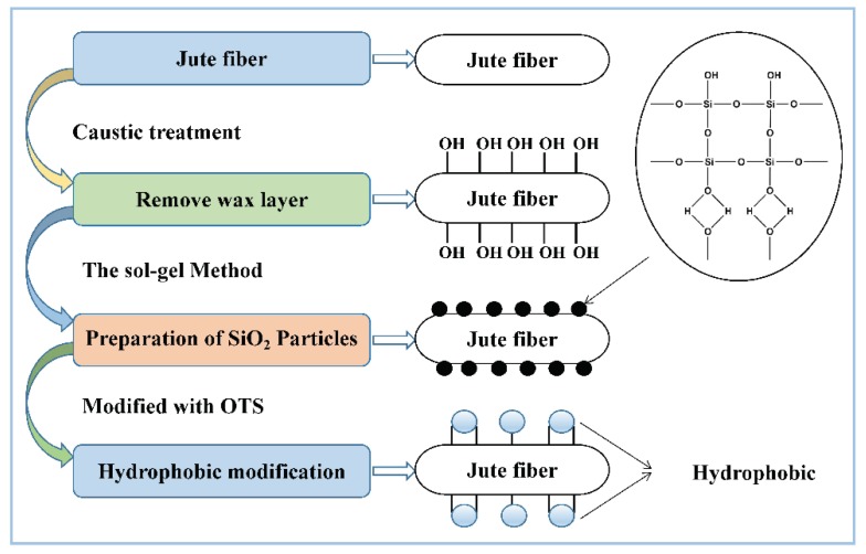
The hydrophobic and lipophilic processes of jute fiber fabrication are described in Figure 1. In this study, caustic pretreatment is done to remove the layer of plant fiber wax, to expose more hydroxyls, and to improve the interface bonding properties. TEOS hydrolyzes as SiO2 particles and adheres to the surface of the material via a chemical effect. Finally, the material is immersed in OTS/n-hexane solution. Since the silica surface is coated with silane, the long-chain hydrophobic alkyls are introduced onto the jute fiber surface; this makes the fiber resistant to wetting by water droplets [8,23].
Figure 1.
The fabrication of hydrophobic and lipophilic jute fibers.
3.1.2. FTIR Spectra and BET Analysis
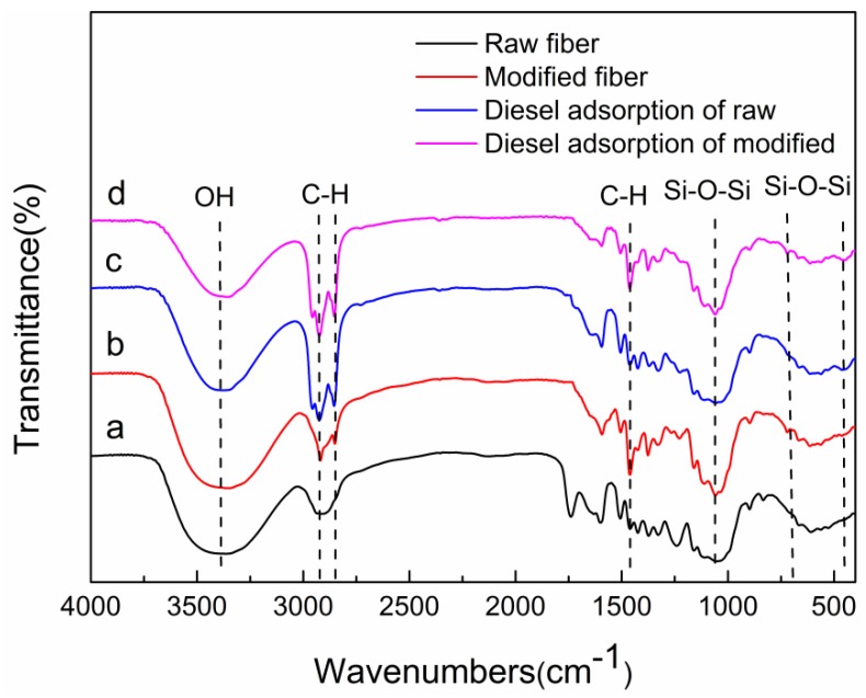
The FTIR spectra of raw and modified jute fibers are shown in Figure 2. Compared with the peak of the raw jute fiber, that of modified jute fiber at 470 cm−1 and the new absorption peaks at 798 and 1112 cm−1 are markedly strengthened; these correspond to Si–O–Si bending, indicating that SiO2 has adhered to the jute fiber surface [8,24,25]. The vibration of –C–H (–CH2 and –CH3) groups are observed at 1430, 2920, and 2855 cm−1. This indicates that OTS and jute have been successfully bonded [26,27]. The peaks at 3430 cm−1 are attributed to –OH stretching vibrations [8,28]. After diesel adsorption, there are no new groups generated, indicating that the adsorption of diesel onto fibers is not through chemical bonding, physical adsorption is dominant [29].
Figure 2.
Fourier transform infrared (FTIR) spectra of (a) raw jute fiber; (b) octadecyltrichlorosilane (OTS) modified; (c) diesel adsorption of raw and (d) diesel adsorption of modified.
The total surface areas (Sp) of the jute fiber were calculated based on the BET model, the specific surface areas of fibers were measured and are shown in Table 1.
Table 1.
The specific surface area of the fiber before and after adsorption of diesel oil.
| Fiber | BET Surface Area |
|---|---|
| Raw fiber | 0.17 ± 0.06 m²/g |
| Modified fiber | 63.84 ± 0.47 m²/g |
| Raw fiber after diesel adsorption | 0.23 ± 0.01 m²/g |
| Modified fiber after diesel adsorption | 0.48 ± 0.01 m²/g |
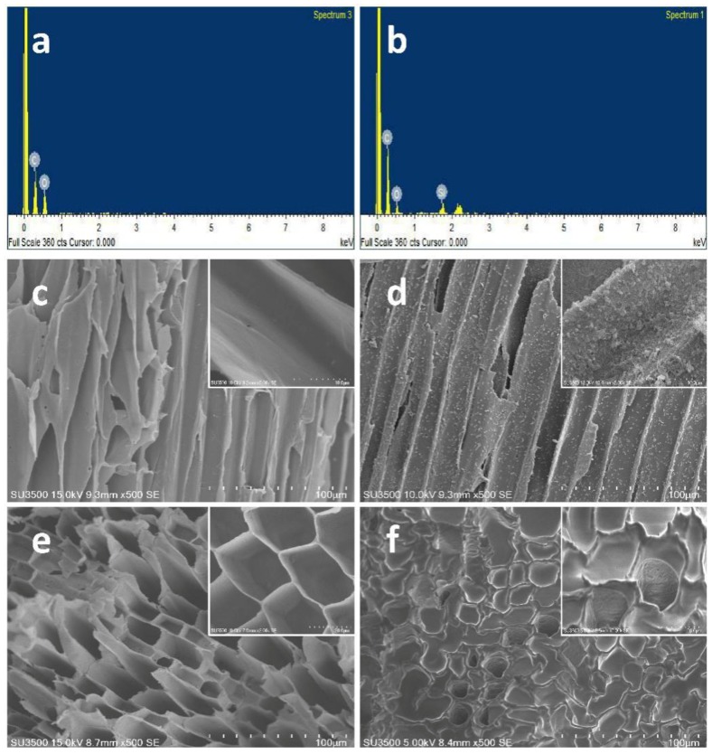
The specific surface area of the modified material is much larger than the raw fiber, because the SiO2 particles attached to the surface contribute to the increase of its specific surface area, which is more conducive to aiding the oil adsorption capacity. After diesel adsorption, there is nearly no difference between the raw and modified fiber. For the modified fiber, the specific surface area after adsorption is much smaller than before, the large deviation in the calculated specific surface area may be caused by the oil plug in the porous structure. (Figure 3f) [29,30,31].
Figure 3.
Energy-dispersive spectrometry (EDS) spectra of (a) raw and (b) modified fibers; scanning electron microscopy (SEM) images of raw (c) and modified (d) fibers; porous structure before (e) and after adsorption (f) of diesel oil.
3.1.3. EDS and SEM Analysis
The chemical compositions of raw and modified jute were characterized by EDS, as shown in Figure 3a,b. The EDS spectrum of raw jute shows the presence of the elements C and O (Figure 3a). In case of the fibers modified with SiO2 and OTS, the peak for Si can also be observed along with those for C and O (Figure 3b). This result reveals that raw fiber is modified successfully with SiO2 and OTS. In order to further study the morphological changes after modification, raw and modified fiber were analyzed by SEM (results are displayed in Figure 3c,d). The results prove that the surface of the raw fiber is relatively smooth (Figure 3c). The magnified image of the fiber also shows a smooth surface of the raw fiber. After coating with SiO2 particles and modification with OTS, the surface becomes much rougher than that of the raw fiber (Figure 3d). The magnified image displays more clearly the dispersion and morphology of SiO2 particles on the surface fiber at higher magnification. The jute fiber has a smooth structure, a thin fiber wall, and a clear porous structure (Figure 3e) before diesel adsorption. After adsorbing, a thick oil film is attached to the surface of the fiber, and oil is also attached to the internal fiber walls of the gap. As a result, the entire fiber wall becomes thicker and most of the porous structure is blocked (Figure 3f) [29].
3.1.4. Wettability Analysis
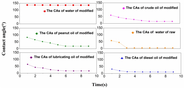
Figure 4 shows that CAs of different liquids change on the fiber surfaces. All of the oil CAs after modification are less than 20° when they reach stable states. According to Young’s equation [32], the modified jute fiber has better wettability for different oils and water CAs of up to 136.2° indicate high hydrophobicity. Because the CA of the water drop on the surface of the raw fibers is too small to be determined by the CA goniometer, the wetted area has to be measured. Therefore, the effective CA is obtained on the basis of the spherical cap. The wetted area of a 3 μL drop is about 20 mm2; therefore its CA is about 5° [33].
Figure 4.
The contact angles (CAs) of different liquids.
3.2. Analysis of Oil Adsorption and Water Adsorption of Modified Jute Fiber in an Oil System and in a Water System
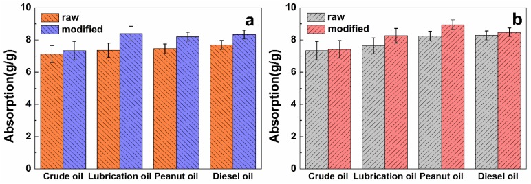
As shown in Table 2, the adsorption capacity of raw and modified fibers approach the maximum value in 15 min, increasing slowly thereafter. After 40 min, the oil and water adsorbed in the fiber lumen reach maximum saturation. After 24 h, adsorption is almost unchanged as compared with that at 40 min. The rapid water adsorption of jute fiber decreases from 6.37 ± 0.06 g/g (raw) to 0.55 ± 0.04 g/g (modified), and the saturated water adsorption decreases from 8.53 ± 0.03 g/g to 0.92 ± 0.02 g/g, indicating excellent hydrophobicity. For the raw jute fiber, the rapid adsorption capacities for crude oil, lubricating oil, peanut oil, and diesel oil are 7.12 ± 0.05 g/g, 7.36 ± 0.04 g/g, 7.45 ± 0.06 g/g, and 7.50 ± 0.02 g/g, respectively. The adsorption rate of the modified fiber increases by 1.03, 1.14, 1.1, and 1.11 times, respectively (Figure 5a). On the other hand, the saturated adsorptions are 7.33 ± 0.07 g/g, 9.53 ± 0.05 g/g, 8.24 ± 0.04 g/g, and 8.38 ± 0.05 g/g, respectively. After modification, they are 7.41 ± 0.03 g/g, 10.29 ± 0.04 g/g, 8.94 ± 0.02 g/g, and 8.48 ± 0.04 g/g, respectively (Figure 5b). Hydrophobicity increases greatly after modification of the raw fiber, and lipophilicity has a certain degree of improvement. All representative results are in g/g (g (liquid)/g (sorbent)).
Table 2.
Water adsorption of raw and modified jute.
| State | 5 | 10 | 15 | 20 | 25 | 30 |
| Raw | 4.23 ± 0.02 | 5.44 ± 0.04 | 6.37 ± 0.06 | 7.12 ± 0.02 | 7.83 ± 0.04 | 8.51 ± 0.03 |
| Modified | 0.32 ± 0.01 | 0.43 ± 0.02 | 0.55 ± 0.02 | 0.61 ± 0.03 | 0.79 ± 0.02 | 0.81 ± 0.02 |
| State | 35 | 40 | 45 | 50 | 55 | 60 |
| Raw | 8.52 ± 0.04 | 8.52 ± 0.04 | 8.52 ± 0.03 | 8.53 ± 0.05 | 8.53 ± 0.02 | 8.53 ± 0.03 |
| Modified | 0.82 ± 0.01 | 0.83 ± 0.03 | 0.91 ± 0.01 | 0.91 ± 0.02 | 0.92 ± 0.01 | 0.92 ± 0.02 |
Figure 5.
(a) Rapid adsorption and (b) saturated adsorption in a pure oil system.
The maximum adsorption capacity of modified jute fiber was compared with the other adsorbents reported used for diesel oil adsorption in the literature (Table 3) [8,29,34,35,36,37,38,39,40]. It was found that the maximum adsorption capacity of the modified fiber is higher than most of the inorganic adsorbents. Although, some adsorbents had better adsorption capacity than modified jute, they are expensive and difficult to biodegrade. So, on the basis of cost and biodegradability, modified jute fiber has better prospects.
Table 3.
Comparative adsorption capacities of various adsorbents for diesel adsorption.
| Adsorbents | Maximum Diesel | References |
|---|---|---|
| Adsorption | ||
| Capacity (g/g) | ||
| Raw cotton fiber | 15 | [8] |
| Mesoporous silica aerogel | 13.6 | [29] |
| Surfactant grafted PDA-PAN nanofiber | 62.53 | [34] |
| The elastic cellulose-based aerogels | 91.82 | [35] |
| Sponge treated by trisilanophenyl POSS | 8.9 | [36] |
| Cotton modified using P-SiO2 nanoparticles | 20 | [37] |
| Kapok modified using P-SiO2 nanoparticles | 23 | [37] |
| Modified hygroscopic magnesium carbonate | 3.017 | [38] |
| Barium sulfate sorbent powder | 1.6 | [39] |
| Treated bark | 2 | [40] |
| Jute fiber modified via the sol-gel method | 8.48 | This study |
3.3. Adsorption Kinetic
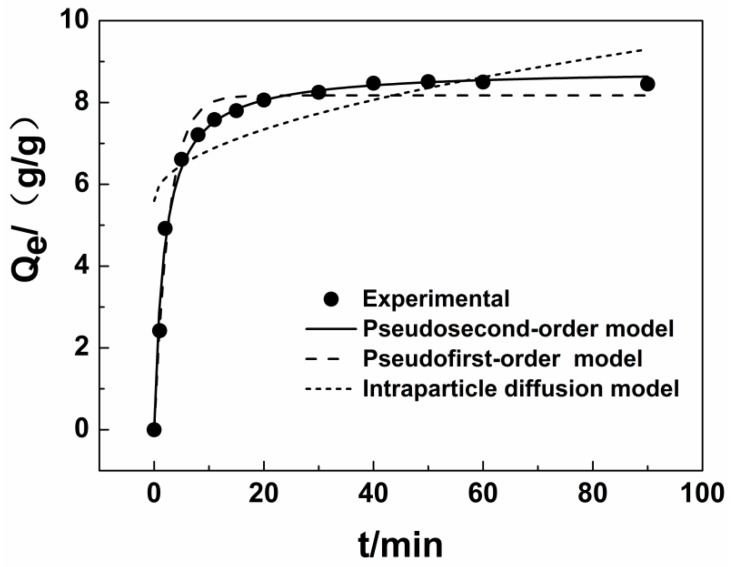
An example of the adsorption kinetics curve for the modified jute (diesel adsorption) is shown in Figure 6. The adsorption rate reflects the amount of modified jute in the oil–water system per unit time. The slope at each point represents the instantaneous adsorption rate. The amount of adsorption increases rapidly (in 8 min). The amount adsorbed increases slowly from 8 to 40 min, and the adsorption equilibrium is reached after 40 min. The reason for this phenomenon is attributed to the large number of internal pores in the modified jute structure. Because diesel is a hydrophobic viscous material and the solubility in water is very low, the diesel can quickly adsorb onto the surface of the material through intermolecular forces. Meanwhile, the diesel is transported into the interior of the jute fiber because of capillary action. The diffusion then becomes more difficult as the pore volume within the fiber decreases, so the amount adsorbed tends to increase very slowly and finally reaches a steady state.
Figure 6.
Kinetics of diesel adsorption on modified jute fiber.
In this study, pseudo-first-order and pseudo-second-order adsorption kinetic models and intraparticle diffusion kinetics model were used to fit the data (Table 4). The correlation coefficient (R2) for the equation for intraparticle diffusion kinetics is less than 0.6, indicating that the adsorption process does not fit the kinetic model. The equilibrium adsorption capacities calculated by using the equations for pseudo-first-order and pseudo-second-order adsorption kinetics are 8.17 ± 0.01 g/g and 8.81 ± 0.01 g/g, respectively; the equilibrium adsorption capacity from measurement is 8.48 ± 0.02 g/g. The calculated equilibrium adsorption capacity is close to the experimental values, but the pseudo-second-order adsorption kinetics model has a higher R2 (0.9918). Therefore, the pseudo-second-order kinetic equation is more suitable for describing diesel adsorption onto jute fiber.
Table 4.
Kinetic parameters for diesel adsorption from an oil/water mixture using modified fiber.
| Kinetic Model | Parameters | Value |
|---|---|---|
| Pseudofirst-order | Qe | 8.1710 |
| K1 | 0.3700 | |
| R2 | 0.9805 | |
| Pseudosecond-order | Qe | 8.8137 |
| K2 | 0.0603 | |
| R2 | 0.9918 | |
| Intraparticle diffusion | K3 | 0.3904 |
| C | 5.5945 | |
| R2 | 0.5449 |
3.4. Adsorption Isotherm
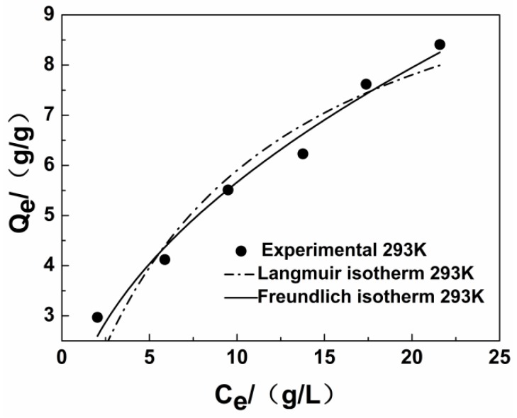
The mathematical model for the adsorption isotherm for modified jute fiber in an oil/water mixture at 293 K is presented in this part. The results are shown in Figure 7 and Table 5. Comparison of the R2 values (Table 5) reveals that the Freundlich model is the best fitting model to explain the adsorption of diesel from modified jute fibers. This result shows that the adsorption of diesel onto the modified fibers studied is multilayer adsorption, and the Freundlich index 1/n is greater than about 0.5, indicating that the material is a favorable absorbent [41].
Figure 7.
Adsorption isotherm of diesel onto modified fiber.
Table 5.
Thermodynamic parameters of diesel adsorption onto modified fiber.
| Isotherm Model | Isotherm Constants | Temperature (293 K) |
|---|---|---|
| Langmuir | Q0 | 11.5209 |
| K1 | 0.1050 | |
| R2 | 0.9075 | |
| Frenudlic | n | 2.0437 |
| K2 | 1.8355 | |
| R2 | 0.9753 |
3.5. Adsorption Thermodynamics
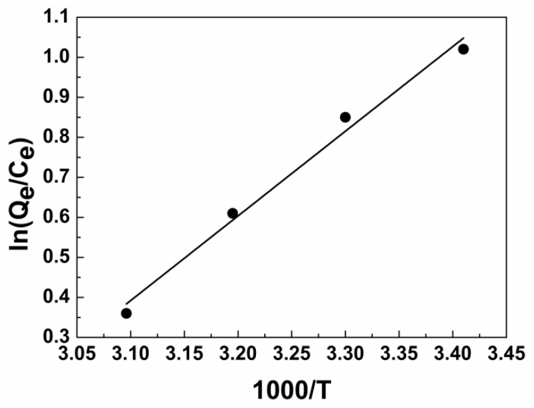
The values of the thermodynamic parameters ΔG and ΔH can be calculated by plotting ln(Qe/Ce) against 1000/T (Figure 8 and Table 6). ΔG values are between −2.48 and −0.09, indicate that in the adsorption process, diesel molecules tend to spontaneously adsorb from the oil/water mixture to the surface of modified material; the absolute value of ΔG decreases with increasing temperature. In other words, higher temperature and weaker driving force of adsorption lead to more difficult absorption of diesel. If ΔS < 0, then the movement of diesel molecules in the modified fiber is limited, the arrangement of molecules is more orderly, and ΔH decreases. On the other hand, ΔH < 0 indicates that diesel adsorption is essentially an exothermic process (|ΔH| < 41 kJ/mol). We consider that the adsorption of diesel oil onto jute occurs through van der Waals forces, the consequence is identical with the results of FTIR.
Figure 8.
Plot of In(Qe/Ce) versus 1000/T for diesel adsorption on modified fiber for thermodynamic parameters.
Table 6.
Thermodynamic parameters for diesel adsorption on modified jute fiber.
| T/K | Ln (Qe/Ce) | ΔG/kJ·mol−1 | ΔH/kJ·mol−1 | ΔS/J·mol−1·k−1 | R2 |
|---|---|---|---|---|---|
| 293 | 1.02 | −2.48 | −17.54 | −51.21 | 0.9821 |
| 303 | 0.85 | −2.14 | |||
| 313 | 0.61 | −1.59 | |||
| 323 | 0.36 | −0.97 |
4. Conclusions
Imparting a rough structure to the surface of jute fiber through the sol–gel method is feasible and effective. Using a modified hydrophobic or oleophilic material, silane, is also practical and useful for marine oil spill cleanup. Compared with other modified materials, natural fiber has sufficient buoyancy and less pollution potential, it is degradable by microorganisms, and it is environment-friendly. For this paper, the capacity for adsorption of different oils and water onto modified jute fiber were studied. The adsorption capacity for water decreased from 8.53 ± 0.03 g/g to 0.92 ± 0.02 g/g after modification. The CA reached 136.2°, which greatly increases hydrophobicity. The adsorption of different oils also showed a certain degree of improvement. For example, the kinetics, isothermal equation, and thermodynamic parameters for diesel fuel adsorption onto modified fiber were analyzed. Kinetic data showed that the pseudo-second-order kinetic equation can better describe the adsorption process, and that gap diffusion affects the adsorption rate. Compared with the Langmuir adsorption isotherm, the Freundlich equation can better describe the equilibrium adsorption data, indicating multilayer adsorption of diesel oil onto the modified jute fiber. The thermodynamic parameters prove that the adsorption of diesel onto modified jute is a spontaneous and favorable process.
Acknowledgments
This work was supported by International Science & Technology Cooperation Program of China (2015DFA90250), the National Natural Science Foundation of China (No. 21677065), and the Ministry of Transport Tianjin Research Institute for Water Transport Engineering Research Innovation Foundation of China (TKS160209).
Author Contributions
N.L. and L.L. designed and performed the experiments. H.Z. and S.P. organized the characterization analyses. N.L. and X.W. contributed to drafting, writing, and editing of the manuscript.
Conflicts of Interest
The authors declare no conflict of interest.
References
- 1.Romero I.C., Toro-Farmer G., Diercks A.R., Schwing P., Muller-Karger F., Murawski S., Hollander D.J. Large-scale deposition of weathered oil in the Gulf of Mexico following a deep-water oil spill. Environ. Pollut. 2017;228:179–189. doi: 10.1016/j.envpol.2017.05.019. [DOI] [PubMed] [Google Scholar]
- 2.Muir B., Bajda T. Organically modified zeolites in petroleum compounds spill cleanup—Production, efficiency, utilization. Fuel Process. Technol. 2016;149:153–162. doi: 10.1016/j.fuproc.2016.04.010. [DOI] [Google Scholar]
- 3.Wang J., Wang A., Wang W. Robustly superhydrophobic/superoleophilic kapok fiber with ZnO nanoneedles coating: Highly efficient separation of oil layer in water and capture of oil droplets in oil-in-water emulsions. Ind. Crops Prod. 2017;108:303–311. doi: 10.1016/j.indcrop.2017.06.059. [DOI] [Google Scholar]
- 4.Hong J.Y., Sohn E.H., Park S., Park H.S. Highly-efficient and recyclable oil absorbing performance of functionalized graphene aerogel. Chem. Eng. J. 2015;269:229–235. doi: 10.1016/j.cej.2015.01.066. [DOI] [Google Scholar]
- 5.Lim T.T., Huang X. Evaluation of kapok (Ceiba pentandra (L.) Gaertn.) as a natural hollow hydrophobic-oleophilic fibrous sorbent for oil spill cleanup. Chemosphere. 2007;66:955–963. doi: 10.1016/j.chemosphere.2006.05.062. [DOI] [PubMed] [Google Scholar]
- 6.Wang J., Zheng Y., Wang A. Coated kapok fiber for removal of spilled oil. Mar. Pollut. Bull. 2013;69:91–96. doi: 10.1016/j.marpolbul.2013.01.007. [DOI] [PubMed] [Google Scholar]
- 7.Pan Y., Wang F., Wei T., Zhang C., Xiao H. Hydrophobic modification of bagasse cellulose fibers with cationic latex: Adsorption kinetics and mechanism. Chem. Eng. J. 2016;302:33–43. doi: 10.1016/j.cej.2016.05.022. [DOI] [Google Scholar]
- 8.Liu F., Ma M., Zang D., Gao Z., Wang C. Fabrication of superhydrophobic/superoleophilic cotton for application in the field of water/oil separation. Carbohydr. Polym. 2014;103:480–487. doi: 10.1016/j.carbpol.2013.12.022. [DOI] [PubMed] [Google Scholar]
- 9.Wu Y., Qi H., Li B., Zhanhua H., Li W., Liu S. Novel hydrophobic cotton fibers adsorbent for the removal of nitrobenzene in aqueous solution. Carbohydr. Polym. 2017;155:294–302. doi: 10.1016/j.carbpol.2016.08.088. [DOI] [PubMed] [Google Scholar]
- 10.Khan M.A., Shehrzade S., Hassan M.M. Effect of Alkali and Ultraviolet (UV) Radiation Pretreatment on Physical and Mechanical Properties of 1,6-Hexanediol Diacrylate—Grafted Jute Yarn by UV Radiation. Polym. Environ. 2003;92:18–24. doi: 10.1002/app.13593. [DOI] [Google Scholar]
- 11.Hassan M.S. Removal of reactive dyes from textile wastewater by immobilized chitosan upon grafted Jute fibers with acrylic acid by gamma irradiation. Radiat. Phys. Chem. 2015;115:55–61. doi: 10.1016/j.radphyschem.2015.05.038. [DOI] [Google Scholar]
- 12.Gao D.W., Hu Q., Pan H., Jiang J., Wang P. High-capacity adsorption of aniline using surface modification of lignocellulose-biomass jute fibers. Bioresour. Technol. 2015;193:507–512. doi: 10.1016/j.biortech.2015.06.138. [DOI] [PubMed] [Google Scholar]
- 13.Arfaoui M.A., Dolez P.I., Dubé M., David E. Development and characterization of a hydrophobic treatment for jute fibers based on zinc oxide nanoparticles and a fatty acid. Appl. Surf. Sci. 2017;397:19–29. doi: 10.1016/j.apsusc.2016.11.085. [DOI] [Google Scholar]
- 14.Dong A., Yu Y., Yuan J., Wang Q., Fan X. Hydrophobic modification of jute fiber used for composite reinforcement via laccase-mediated grafting. Appl. Surf. Sci. 2014;301:418–427. doi: 10.1016/j.apsusc.2014.02.092. [DOI] [Google Scholar]
- 15.Equipment S., Products M. Standard Test Method for Performance of Griddles 1. Annu. B ASTM Stand. 2005;5:1–17. [Google Scholar]
- 16.Lagergren S. About the theory of so-called adsorption of soluble substance. Kungliga Sven. Vetenskapsakademiens Handl. 1898;24:1–39. [Google Scholar]
- 17.Ho Y.S., Mckay G. Kinetic Models for the Sorption of Dye from Aqueous Solution by Wood. Process Saf. Environ. Prot. 1998;76:183–191. doi: 10.1205/095758298529326. [DOI] [Google Scholar]
- 18.Weber W.J., Morris J.C. Kinetics of adsorption on carbon from solution. J. Sanit. Eng. Div. Am. Soc. Civ. Eng. 1963;89:31–59. [Google Scholar]
- 19.Langmuir I. The adsorption of gases on plane surfaces of glass, mica and platinum. J. Am. Chem. Soc. 1918;40:1361–1403. doi: 10.1021/ja02242a004. [DOI] [Google Scholar]
- 20.Freundlich H. Über die Adsorption in Lösungen. Z. Phys. Chem. 1907;57:385–470. doi: 10.1515/zpch-1907-5723. [DOI] [Google Scholar]
- 21.Khan T.A., Dahiya S., Ali I. Use of kaolinite as adsorbent: Equilibrium, dynamics and thermodynamic studies on the adsorption of Rhodamine B from aqueous solution. Appl. Clay Sci. 2012;69:58–66. doi: 10.1016/j.clay.2012.09.001. [DOI] [Google Scholar]
- 22.Zhao G., Li J., Wang X. Kinetic and thermodynamic study of 1-naphthol adsorption from aqueous solution to sulfonated graphene nanosheets. Chem. Eng. J. 2011;173:185–190. doi: 10.1016/j.cej.2011.07.072. [DOI] [Google Scholar]
- 23.Bae G.Y., Min B.G., Jeong Y.G., Lee S.C., Jang J.H., Koo G.H. Superhydrophobicity of cotton fabrics treated with silica nanoparticles and water-repellent agent. J. Colloid Interface Sci. 2009;337:170–175. doi: 10.1016/j.jcis.2009.04.066. [DOI] [PubMed] [Google Scholar]
- 24.Hsieh C.T., Wu F.L., Chen W.Y. Superhydrophobicity and superoleophobicity from hierarchical silica sphere stacking layers. Mater. Chem. Phys. 2010;121:14–21. doi: 10.1016/j.matchemphys.2009.12.031. [DOI] [Google Scholar]
- 25.Wang J., Zheng Y., Wang A. Superhydrophobic kapok fiber oil-absorbent: Preparation and high oil absorbency. Chem. Eng. J, 2012;213:1–7. [Google Scholar]
- 26.Sai H., Fu R., Xing L., Xiang J., Li Z., Li F., Zhang T. Surface modification of bacterial cellulose aerogels’ web-like skeleton for oil/water separation. ACS Appl. Mater. Interfaces. 2015;7:7373–7381. doi: 10.1021/acsami.5b00846. [DOI] [PubMed] [Google Scholar]
- 27.Wang C., Piao C., Lucas C. Synthesis and characterization of superhydrophobic wood surfaces. J. Appl. Polym. Sci. 2011;119:1667–1672. doi: 10.1002/app.32844. [DOI] [Google Scholar]
- 28.He Y.D., Zhai Y.B., Li C.T., Yang F., Chen L., Fan X.P., Peng W.F., Fu Z.M. The fate of Cu, Zn, Pb and Cd during the pyrolysis of sewage sludge at different temperatures. Environ. Technol. 2010;31:567–574. doi: 10.1080/09593330903514466. [DOI] [PubMed] [Google Scholar]
- 29.Zhang C., Chong D., Zhang H., Peng S., Xin W., Hu Y. Regeneration of mesoporous silica aerogel for hydrocarbon adsorption and recovery. Mar. Pollut. Bull. 2017;122:129–138. doi: 10.1016/j.marpolbul.2017.06.036. [DOI] [PubMed] [Google Scholar]
- 30.Ajay K., Amit K., Gaurav S., Ala’a H., Al-M M.N., Ayman A.G., Florian J.S. Quaternary magnetic BiOCl/g-C3N4/Cu2O/Fe3O4 nano-junction for visible light and solar powered degradation of sulfamethoxazole from aqueous environment. Chem. Eng. J. 2018;334:462–478. [Google Scholar]
- 31.Naushad M., Ahamad T., Al-Maswari B.M., Alqadami A.A., Alshehri S.M. Nickel ferrite bearing nitrogen-doped mesoporous carbon as efficient adsorbent for the removal of highly toxic metal ion from aqueous medium. Chem. Eng. J. 2017;330:1351–1360. doi: 10.1016/j.cej.2017.08.079. [DOI] [Google Scholar]
- 32.Furmidge C.G.L. Studies at phase interfaces. I. The sliding of liquid drops on solid surfaces and a theory for spray retention. J. Colloid Sci. 1962;17:309–324. doi: 10.1016/0095-8522(62)90011-9. [DOI] [Google Scholar]
- 33.Wu C.J., Li Y.F., Woon W.Y., Sheng Y.J., Tsao H.K. Contact Angle Hysteresis on Graphene Surfaces and Hysteresis-free Behavior on Oil-infused Graphite Surfaces. Appl. Surf. Sci. 2016;385:153–161. doi: 10.1016/j.apsusc.2016.05.059. [DOI] [Google Scholar]
- 34.Almasian A., Jalali M.L., Chizari Fard Gh., Maleknia L. Surfactant grafted PDA-PAN nanofiber: Optimization of synthesis, characterization and oil absorption property. Chem. Eng. J. 2017;326:1232–1241. doi: 10.1016/j.cej.2017.06.040. [DOI] [Google Scholar]
- 35.Yin T., Zhang X., Liu X., Wang C. Resource recovery of eichhornia crassipes, as oil superabsorbent. Mar. Pollut. Bull. 2017:267–274. doi: 10.1016/j.marpolbul.2017.01.064. [DOI] [PubMed] [Google Scholar]
- 36.Wang Z., Ma H., Chu B., Hsiao B.S. Super-hydrophobic modification of porous natural polymer “luffa sponge” for oil absorption. Polymer. 2017;126:470–476. doi: 10.1016/j.polymer.2017.05.068. [DOI] [Google Scholar]
- 37.Ju H.L., Kim D.H., Sang W.H., Bo R.K., Park E.J., Jeong M.G., Kim J.H., Kim Y.D. Fabrication of superhydrophobic fibre and its application to selective oil spill removal. Chem. Eng. J. 2016;289:1–6. [Google Scholar]
- 38.Patowary M., Ananthakrishnan R., Pathak K. Chemical modification of hygroscopic magnesium carbonate into superhydrophobic and oleophilic sorbent suitable for removal of oil spill in water. Appl. Surf. Sci. 2014;320:294–300. doi: 10.1016/j.apsusc.2014.09.053. [DOI] [Google Scholar]
- 39.Patowary M., Ananthakrishnan R., Pathak K. Superhydrophobic and oleophilic barium sulfate material for oil spill clean-ups: Fabrication of surface modified sorbent by a one-step interaction approach. J. Chem. Eng. 2014;2:2078–2084. doi: 10.1016/j.jece.2014.09.007. [DOI] [Google Scholar]
- 40.Haussard M., Gaballah I., Kanari N., De D. P., Barrès O., Villieras F. Separation of hydrocarbons and lipid from water using treated bark. Water Res. 2003;37:362–374. doi: 10.1016/S0043-1354(02)00269-5. [DOI] [PubMed] [Google Scholar]
- 41.Cheng W.P., Gao W., Cui X., Ma J.H., Li R.F. Phenol adsorption equilibrium and kinetics on zeolite X/activated carbon composite. J. Taiwan Inst. Chem. Eng. 2016;62:192–198. doi: 10.1016/j.jtice.2016.02.004. [DOI] [Google Scholar]


