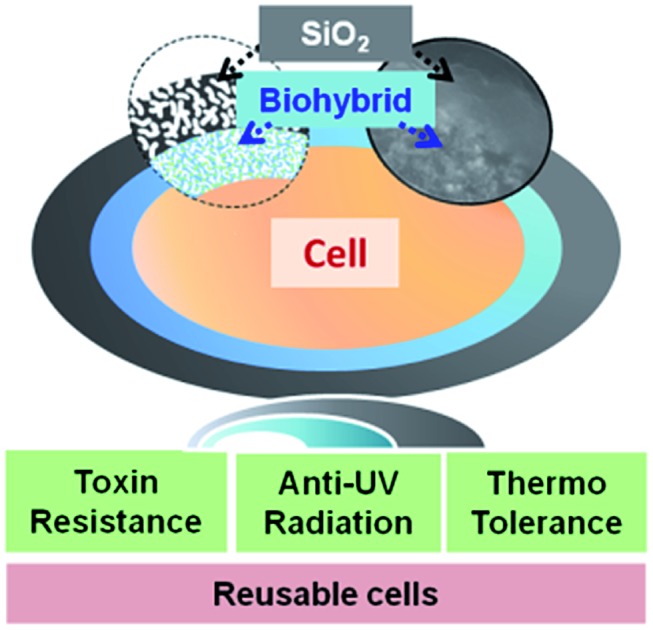
 A bilayered nanoshell is used to encapsulate a single cell for high stability after hostile stimulation.
Abstract
Single cell surface engineering provides the most efficient, non-genetic strategy to enhance cell stability. However, it remains a huge challenge to improve cell stability in complex artificial environments. Here, a soft biohybrid interfacial layer is fabricated on individual living-cell surfaces by their exposure to a suspension of gold nanoparticles and l-cysteine to form a protecting functional layer to which porous silica layers were bound yielding pores with a diameter of 3.9 nm. The living cells within the bilayered nanoshells maintained high viability (96 ± 2%) as demonstrated by agar plating, even after five cycles of simultaneous exposure to high temperature (40 °C), lyticase and UV light. Moreover, yeast cells encapsulated in bilayered nanoshells were more recyclable than native cells due to nutrient storage in the shell.
Introduction
Microorganisms have been used for centuries as living factories for various applications, such as water purification, biofuel production and biocatalysis.1–5 A common limitation in many microbial factories is the low microbial survival in their hostile factory environment.6 Genetic approaches to equip microorganisms against a hostile environment bear the risk of creating a “super-bug” that may not be controlled.7–11 An alternative, non-genetic approach that avoids this potential risk is to encapsulate a single microbial cell in a protective, surface-engineered nanoshell that allows the exchange of nutrients and waste while providing protection against a hostile environment.12–15 Eukaryotic yeast cells in the fermentation industry, most notably Saccharomyces cerevisiae, need protection in their alcohol-producing factory against high alcohol concentrations and non-optimal pH and temperature,16,17 making S. cerevisiae one of the most widely studied organisms in cell surface engineering.18,19 Despite the eukaryotic yeast cell wall being different from the mammalian cell surface,13,20 the yeast cell bears similarity in terms of cell surface constituents and cell reproduction cycle to tissue cells.21,22 Therefore, S. cerevisiae is also frequently used as a model organism for eukaryotic tissue cells in general to develop new encapsulation technologies.23–25 A typical example of biological encapsulation found in nature is the egg shell configuration, which consists of bilayers as its protective shell. The inner mammillary layer of an egg-shell offers a soft and semi-permeable interface to the hard, spongy exterior shell providing mechanical strength to the embryo, while allowing exchange of minerals and water, and respiration.26 The macroscopic structure of an egg shell can be encapsulated by depositing an inner electrolyte layer directly onto the cell surface. This provides a catalytic platform for outer inorganic layer formation by interaction with oppositely charged polyelectrolytes to protect cells against high light intensities, external zymolyase or high temperature.27–32 However, direct deposition of polyelectrolytes on cell surfaces hampers essential cell viability, limiting their factory performance.33 In most microbial factories however, cells are simultaneously exposed to multiple, hostile stimuli,34 such as non-optimal temperatures or pH, toxins and intense UV light exposure. Single cell encapsulation methods have seldom been utilized to protect cells against multiple, simultaneously occurring hostile stimuli.
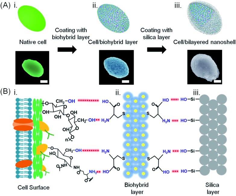
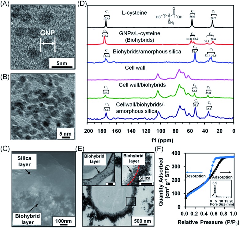
Here, a bilayered nanoshell was created around a single S. cerevisiae cell with the aim of offering protection against multiple, simultaneously occurring hostile stimuli. The cells (Fig. 1A-i and S1-i†) were first exposed for 5 min to a suspension of a biohybrid containing gold nanoparticles and l-cysteine molecules. Gold nanoparticle (2–3 nm in diameter, Fig. 2A) exposure was performed in an l-cysteine solution, since gold nanoparticles functionalized with l-cysteine cannot enter a cell.35 Rather than entering the cell, amino-coated gold nanoparticles form hydrogen bonds with abundantly present hydroxyl groups of polysaccharides on the yeast cell surface, yielding a nanoporous biohybrid layer (Fig. 1A-ii and S1-ii†) with an average pore size of approximately 10 nm (Fig. 2B). Thermogravimetric analysis showed a mass loss of 27% from 200 °C to 570 °C attributed to the decomposition of l-cysteine molecules in the biohybrid layer (Fig. S2†). After the self-assembly of the biohybrid layer, the cells were exposed to amorphous silica in suspension and subsequently self-assembled onto the biohybrid layer to form a bilayered nanoshell (Fig. 1A-iii and S1-iii†). In the formation of the biohybrid/silica bilayered nanoshell on the cell surface, the biohybrid layer acted as a bridge to link the functional groups of the cell surface with the hydroxyl groups of silica (Fig. 1B). Surface charge plays a crucial role in the formation of bilayered nanoshells; hence, zeta potentials of the cells and nanoshells, reflecting their surface charges, were measured. Zeta potentials of native cells remained negative after application of the biohybrid layer and after encapsulation with the bilayered nanoshell (Table S1†). Considering that the native cell surface as well as the biohybrids and silica carry a negative charge (also shown in Table S1†), it is proposed that the biohybrids electrostatically attract M+ cations from solution that are subsequently induced to assemble onto the negatively charged cell surface through electrostatic interactions, analogous to S–M+S– interactions in a microphase mechanism between organic and inorganic phases.36 After this self-assembly process, hydrogen bonding between available functional groups of the biohybrids further attracts negatively charged silica to form the outer layer of the bilayered nanoshells (Fig. 2C).
Fig. 1. Bilayered nanoshell formation on a single yeast cell. (A) Exposure of a cell (i) to a solution containing l-cysteine-coated gold nanoparticles, (ii) yielding a cell with a biohybrid layer, followed by self-assembly of silica, (iii) yielding a bilayered nanoshell. Artificial colors were used in the SEM micrographs (the scale bar equals 1 μm). Authentic micrographs can be found in Fig. S1.† (B) Sequential steps in the formation of a bilayered nanoshell: (i) a yeast cell surface possessing abundant hydroxyl groups and sparsely distributed amino groups and carboxyl groups, (ii) a biohybrid layer composed of amino-covered gold nanoparticle groups and carboxyl groups (yellow dots and blue layers represent gold nanoparticles and l-cysteine molecules, respectively), and (iii) the silica outer surface, exposing hydroxyl groups. Red dashed lines represent hydrogen bonding between functional groups on the cell surface with the biohybrid layer and functional groups of the biohybrid layer with the amorphous silica layer, as indicated in the lower part.
Fig. 2. Characterization of bilayered nanoshells, encapsulating a single S. cerevisiae cell. (A) TEM micrograph of individual gold nanoparticles (denoted as GNP). (B) Nanopores in the biohybrid layer. (C) High-magnification SEM micrograph of a cross-section of the bilayer around a yeast cell. (D) 13C solid-state NMR spectra of different components making up the bilayered nanoshell. (E) TEM micrographs of an encapsulated yeast cell with a bilayered nanoshell (indicated by the black square), together with a higher magnification image of the biohybrid layer (top left inset; the scale bar equals 200 nm) and the boundary of the inner and outer layers indicated (top right inset; the scale bar equals 200 nm). The inner and outer layers are indicated by arrows while their boundary is indicated for clarity by the red dashed line. (F) N2 adsorption/desorption isotherm and the corresponding pore-size distribution (inset) of silica layers. Measurements were taken at standard temperature and pressure (STP) of 1 atmosphere and 0 °C.
Results and discussion
Solid state NMR was employed (Fig. 2D) to confirm the interactions described above in extracted S. cerevisiae cell walls that were devoid of any intracellular content (Fig. S3†). l-Cysteine showed three sets of carbon resonances at 173.9 ppm (C1), 56.6 ppm (C2) and 28.7 ppm (C3). Upon interaction with gold, both carbon resonance sets shifted slightly to 176.2 ppm, 57.8 ppm and 28.0 ppm, respectively. New resonance sets developed at 54.3 ppm and 36.1 ppm, resulting from interaction between gold and sulfur in l-cysteine, while the small resonance shifts indicated hydrogen bonding between gold and l-cysteine in the biohybrid layer.37–39 Upon interaction of the biohybrid layer with amorphous silica, the amino and carboxyl groups of the biohybrids interact with Si-OH groups of the silica, giving rise to splitting of the C3 carbon resonance into two components at 32.1 ppm and 30.5 ppm. The C2 and C3 resonance sets observed in l-cysteine were absent in native yeast cell walls, but appeared in cell walls with a biohybrid layer of l-cysteine-coated gold nanoparticles and after its bilayering with amorphous silica. C1, C2 and C3 resonances in a cell wall associated system differed from the carbon resonances in biohybrid/amorphous silica bilayers due to the weak interactions between the amino and carboxylate groups of the gold/l-cysteine biohybrid layer and hydroxyl groups in the yeast cell wall. NMR data suggested that the biohybrid layer interacts with functional cell surface groups as well as with hydroxyl groups of silica. The bilayered nanoshells can be directly imaged using electron microscopy. In scanning electron microscopy (SEM), the inner biohybrid layer of the bilayered nanoshell showed a nanoporous structure, while the outer layer possessed a dense structure of self-assembled silica with a uniform thickness of approximately 200 nm (Fig. 2C). Transmission electron microscopy (TEM) images of microtome-sliced yeast encapsulated in a bilayered nanoshell showed that yeast cells remained fully intact upon encapsulation (Fig. 2E and insets) with an inner layer thickness of approximately 70 nm. The outer silica layer was relatively dense as compared to the inner layer, providing a narrow pore size distribution with an average pore size of 3.9 nm (Fig. 2F), which is generally considered small enough to allow protection of encapsulated cells,40 and gaseous and aqueous nutrient exchange.
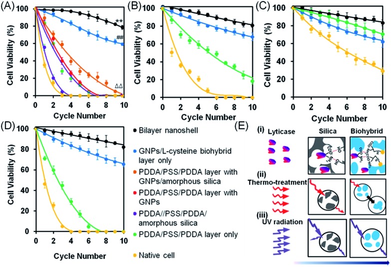
To evaluate the viability of encapsulated yeast cells in a complex environment with multiple, simultaneously acting hostile stimuli, native S. cerevisiae cells were encapsulated in bilayered nanoshells and simultaneously exposed to lyticase (a naturally occurring toxin41,42), high temperature (40 °C, a typical temperature in process technology), UV light and recycling, recycling being established by centrifugation after hostile stimulation and re-exposure to the hostile environment.43 On assessment of viability using agar plating, the cells encapsulated in bilayered nanoshells showed 86% viability after being recycled ten times in the absence of hostile stimuli, which was significantly higher than that observed for native cells without encapsulation, showing only 50% viability under similar conditions. Since recycling involves nutrient deprivation and physical stress,44 enhanced viability after recycling in the absence of hostile stimuli is likely due to storage of nutrients in the bilayered nanoshells. Upon exposure to multiple, simultaneously acting hostile stimuli, the cells encapsulated in bilayered nanoshells showed the highest viability compared to several other protective encapsulations, maintaining 79% viability up to at least ten cycles (Fig. 3A). This indicated robust reusability, which was significantly (p < 0.01; paired Student's t-test) higher than that observed for native cells (Fig. 3A), as confirmed using fluorescence microscopy on live/dead stained yeast cells after multiple, simultaneously acting stimuli (Fig. S4†). A considerable part of this protection stems from the biohybrid layer (Fig. 3A), although the protection offered by the biohybrid layer alone was significantly smaller than that offered by the nanoporous bilayered nanoshell (p < 0.01; paired Student's t-test). Encapsulation with shells composed of single nanoporous layers of amorphous silica or gold nanoparticles both with and without an intermediate polyelectrolyte layer offered significantly (p < 0.01; paired Student's t-test) less protection than the biohybrid layers alone, but viability after multiple cycles of simultaneous, hostile stimuli still remained significantly (p < 0.01; paired Student's t-test) higher than that of native cells. A polyelectrolyte layer alone did not offer significant protection as compared to native cells (p > 0.05; paired Student's t-test). Additionally, as compared to other polyelectrolyte solutions applied in different encapsulation procedures, a solution of l-cysteine with gold nanoparticles used to form our biohybrid layer did not affect the morphology of the yeast cells (Fig. S5†). Similar bilayered nanoshells can be formed using aspartic acid or lysine molecules as the polyelectrolyte component of the biohybrids (Fig. S6†).
Fig. 3. Viability of S. cerevisiae after multiple cycles of simultaneous or single hostile stimuli, assessed using agar plating. (A) Yeast cell viability after multiple cycles of simultaneous hostile stimuli with lyticase, high temperature (40 °C) and UV light. (B) Under similar conditions, but with lyticase exposure alone. (C) Under similar conditions, but with high temperature exposure alone. (D) Under similar conditions, but with UV light exposure alone. Data indicate the percentage of colony forming units on agar plates, with error bars indicating standard deviations over five separate experiments with different yeast cultures. 100% viability represents pre-stimulus CFU levels. (E) Proposed mechanisms of protection by bilayered nanoshells against the different single stimuli applied: (i) lyticase, (ii) thermal stress, and (iii) UV radiation. Arrows indicate the penetration of stimuli through the outer silica layer and inner biohybrid layer.
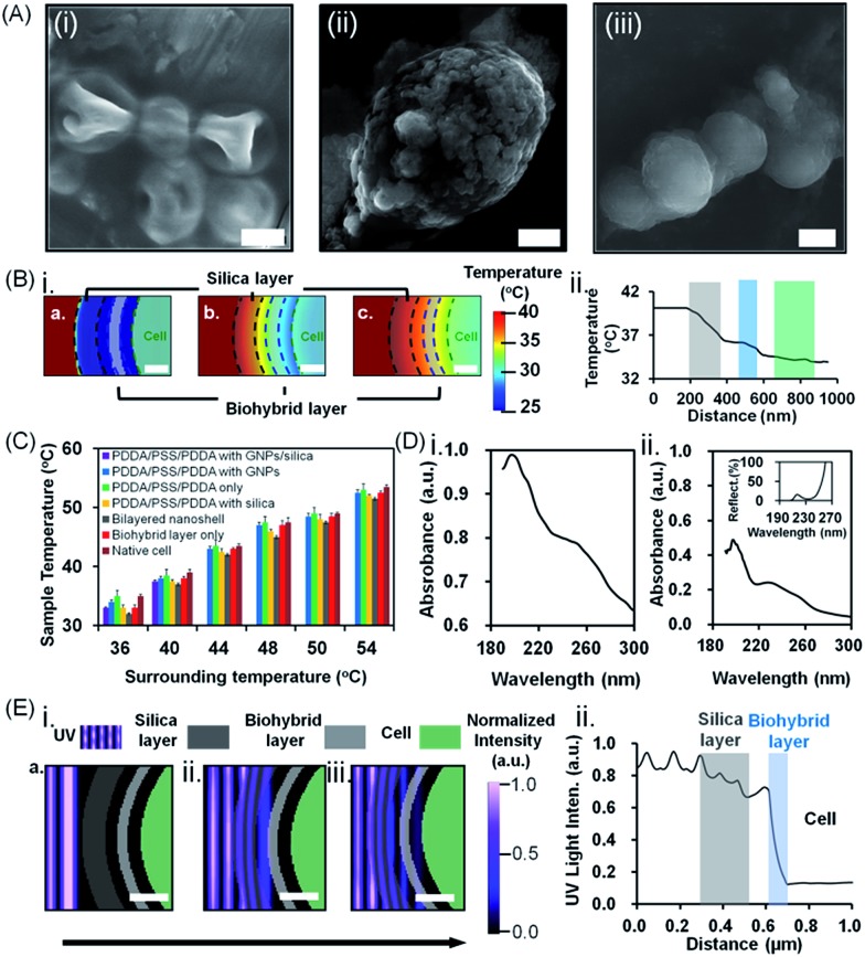
The above, simultaneously acting hostile stimuli were also separately applied (Fig. 3B–D). Differently encapsulated yeast cells exhibited a similar ranking of protection in the presence of lyticase (Fig. 3B), at high temperature (Fig. 3C) or under UV light exposure (Fig. 3D) alone, as observed in the presence of simultaneous, multiple hostile stimuli (Fig. 3A). The cells encapsulated in bilayered nanoshells maintained 80% of their viability after ten cycles of exposure to lyticase, while native cells were virtually all dead (Fig. 3B). Lyticase protection of the bilayered shells stemmed predominantly from the absorption of lyticase in the nanopores of biohybrid layer, and the adsorption of negatively charged carboxyl groups in lyticase to amino acids in the biohybrid layer (Fig. 3E-i). As a net result, biohybrids entrapped 2–3 fold more lyticase than the self-assembled amorphous silica (Table S2†). This also explains why cells after being recycled ten times and encapsulated with a biohybrid layer had higher viability (65%) than cells encapsulated with PDDA/PSS/PDDA/silica (22%; Fig. 3B; see the ESI† for details). Both native as well as yeast cells protected by a biohybrid layer (Fig. 3C) were significantly better able to withstand high temperature as a single hostile stimulus than when combined with lyticase and UV radiation (Fig. 3). However, cells encapsulated in a bilayered nanoshell maintained their original morphologies upon exposure to high temperature, while native cells without bilayered encapsulation clearly shrank (Fig. 4A). A two-dimensional Finite-Difference Time Domain (FDTD) method was used to simulate the heat transfer through bilayered nanoshells from a constant surrounding temperature of 40 °C to a cell (Fig. 4B and Movie S1†). The simulation shows a clear retardation of heat transfer into the cell due to heat uptake arising from the heat capacity of the biohybrid and silica layers and implies a temperature increase of the bilayered nanoshell before the encapsulated cell heats up. The silica layer aids the retardation of heat transfer slightly more than the biohybrid layer. To further investigate the effect of thermal protection of the nanoshells, cell surface temperature measurements were conducted on freeze-dried cells (Fig. 4C). The cells encapsulated in bilayered nanoshells maintained a stable temperature after about 5 min of exposure to high temperature and remained on average 2 °C cooler than native cells without encapsulation, while a silica shell could only maintain cells 1 °C cooler than native cells. This suggests strong heat absorption and diffusion45 in bilayered shells, which were not present in PDDA/PSS/PDDA encapsulated cells (Fig. 3E-ii). Similarly, the protection offered by bilayered nanoshells against UV radiation (Fig. 3D) was envisaged as being a result of UV absorption (Fig. 3E-iii). UV-vis spectra clearly showed the absorption of biohybrid and silica layers in the range of 190–300 nm (Fig. 4D). To better understand the protection offered by bilayered nanoshells against UV light, the FDTD method was also used to simulate the propagation of an electromagnetic field through the bilayers encapsulating the cells, as governed by Ampere's and Faraday's laws. Relevant differential equations were solved using the Yee algorithm,46 based on the refractive and absorptive properties of the bilayered nanoshell as included in the complex refractive index. Simulations showed that the major effect of the silica composing the outer layer was to reflect UV light preventing its cell entry (Fig. 4E and Movie S2†), yielding an intensity attenuation of 26% with respect to the incoming intensity. The biohybrid inner layer on the other hand mainly served to absorb UV light (59%, Fig. 4E-ii).
Fig. 4. Protection of S. cerevisiae cells encapsulated in bilayered nanoshells against lyticase, high temperature and UV light exposure. (A) SEM images of (i) native cells, (ii) cells encapsulated in a biohybrid layer alone (the scale bar equals 1 μm) and (iii) cells encapsulated in a bilayered nanoshell (the scale bar equals 5 μm) after exposure to a temperature of 40 °C for 12 h. (B) Simulated (i) attenuation of thermal stress and (ii) temperature distribution through the silica (grey shaded) and biohybrid layer (blue shaded) to the cell (green shaded). The scale bar equals 200 nm. (C) Surface temperature of differently encapsulated yeast cells exposed to a range of different surrounding temperatures (36–54 °C). Data represent averages with standard deviations over 3 separate yeast cultures. (D) UV absorption spectra of (i) biohybrids and (ii) silica. The inset shows the percentage reflection of light through the amorphous silica layer. (E) Simulated (i) attenuation of UV light and (ii) intensity distribution through the outer silica layer (grey shaded) and inner biohybrid layer (blue shaded). The scale bar equals 200 nm. The arrow indicates the direction of light propagation.
Apart from offering protection, cell encapsulation also offers possibilities to provide a cell with additional functionalities to expand its applications. Electrically conductive cells, for instance, have been produced by integrating gold nanorods into protective shells for use as bio-electrodes and monitoring of cell responses to external stimuli.47,48 In the present work, graphene was also integrated into the bilayered nanoshells to endow them with electrical conductivity (Fig. 5A–C). Native cells had low electrical conductivity (0.9 × 10⁻³ S m–1). However, the introduction of graphene into the silica outer layer yielded a significantly higher electrical conductivity (8.5 × 10⁻³ S m–1), i.e. 9 fold higher than that of native cells and 3 fold higher than that of cells with a biohybrid layer alone (Fig. 5C). Thus, both the biohybrid layer and the incorporation of graphene contributed to increased electrical conductivity. Similarly, Fe3O4 magnetic nanoparticles could be incorporated into bilayered nanoshells (Fig. 5A and D) allowing easy and rapid separation of magnetic cells from suspension (Fig. 5E). Moreover, after 10 cycles, the encapsulated cells functionalized with graphene and magnetic particles maintained 82% and 78% of their original viabilities (Fig. 5F), indicating that the addition of electrically conductive or magnetic functionalities does not negatively impact the protection offered by bilayered nanoshells against simultaneous, hostile stimuli.
Fig. 5. Post-functionalization of S. cerevisiae cells encapsulated in bilayered nanoshells. (A) Schematic of post-functionalized, bilayered nanoshell encapsulated cells with graphene and magnetic nanoparticles. (B) SEM image of a yeast cell with a graphene-based bilayered nanoshell (the scale bar equals 5 μm). (C) Electrical conductivity of differently encapsulated yeast cells and yeast cells with a graphene-based bilayered nanoshell. (D) SEM image of Fe3O4-based bilayered nanoshell encapsulated cells and EDX line scan for elemental Fe (inset). The scale bar equals 5 μm. (E) Magnetic separation of yeast cells encapsulated with magnetic iron oxide nanoparticles. The scale bar equals 0.5 cm. (F) Viability of yeast cells encapsulated in bilayered nanoshells with post-functionalities after multiple cycles of simultaneous hostile stimuli with lyticase, high temperature (40 °C) and UV light. Note that cells in bilayered nanoshells with and without graphene or Fe3O4 demonstrate comparable viability after recycling (see also Fig. 3A).
Conclusion
A bilayered nanoshell composed of a biohybrid layer of l-cysteine-coated gold nanoparticles and self-assembled amorphous silica, allowing electrically conductive and magnetic functionalization, was developed to protect a single S. cerevisiae cell against simultaneous, multiple hostile stimuli, including lyticase, high temperature, UV radiation and recycling. As compared to polyelectrolytes as a potential interface for the outer layer formation, the biohybrid layer provided high biocompatibility without affecting cell viability and morphology. Unlike dense inorganic shells,27,49 the fabricated bilayered nanoshells had nanopores which allowed gaseous and liquid nutrient exchange. Important for practical applications is the fact that the developed bilayered nanoshells offer better possibilities to re-use living cells compared to native cells without bilayered nanoshells, and also in the absence of hostile stimuli. Moreover, the fabricated bilayered nanoshells may constitute an alternative to protect and maintain mammalian cells alive in hydrogel-based 3D cell cultures and microdroplets, as in organ-on-a-chip devices, cell sorting, and cell therapy.50–54 As compared to conventional materials as a potential interface for the outer layer formation, the biohybrid layer had high biocompatibility without affecting cell viability and morphology.55
Conflicts of interest
H. J. B. is also director of a consulting company, SASA BV. There are no conflicts to declare with respect to this paper.
Supplementary Material
Acknowledgments
This work was supported by the National Key R&D Program of China (2017YFC1103800), PCSIRT (IRT_15R52), NSFC (U1663225, U1662134, 51472190, 51611530672, and 21711530705), ISTCP (2015DFE52870), and HPNSF (2016CFA033 and 2014CFB778). This study was also supported by the Open Project Program of State Key Laboratory of Petroleum Pollution Control (PPC2016007) and CNPC Research Institute of Safety and Environmental Technology. N. J. carried out all the experiments and wrote the paper. X. Y. Y. conceived the project, provided the idea, and designed and guided the experiments. B. L. S. conceived the project, and supported the scientific and technological platform. G. L. Y. prepared gold nanoparticles and performed cell culture. L. S. carried out N2 adsorption and desorption measurements. A. K. Y. revised the paper. Y. M. performed simulations. Y. X. X. drew a part of the drawings. H. J. B. organized, wrote, revised the paper and provided technological guidance. All the authors discussed the results and analyzed the data.
Footnotes
†Electronic supplementary information (ESI) available. See DOI: 10.1039/c8sc01130c
References
- Hepworth L. J., France S. P., Hussain S., Both P., Turner N. J., Flitsch S. L. ACS Catal. 2017;7:2920. [Google Scholar]
- Takagi T., Yokoi T., Shibata T., Morisaka H., Kuroda K., Ueda M. Appl. Microbiol. Biotechnol. 2016;100:1723. doi: 10.1007/s00253-015-7035-x. [DOI] [PubMed] [Google Scholar]
- Liu Q., Wu C., Cai H., Hu N., Zhou J., Wang P. Chem. Rev. 2014;114:6423. doi: 10.1021/cr2003129. [DOI] [PubMed] [Google Scholar]
- Loqué D., Scheller H. V., Pauly M. Curr. Opin. Plant Biol. 2015;25:151. doi: 10.1016/j.pbi.2015.05.018. [DOI] [PubMed] [Google Scholar]
- Wang L., Hu Z.-Y., Yang X.-Y., Zhang B.-B., Geng W., Van Tendeloo G., Su B.-L. Chem. Commun. 2017;53:6617. doi: 10.1039/c7cc01283g. [DOI] [PubMed] [Google Scholar]
- Bishop J., Nelson G., Lamb J. J. Microencapsulation. 1998;15:761. doi: 10.3109/02652049809008259. [DOI] [PubMed] [Google Scholar]
- Mayo O. Meanjin. 2014;73:78. [Google Scholar]
- Arias C. A., Murray B. E. N. Engl. J. Med. 2009;360:439. doi: 10.1056/NEJMp0804651. [DOI] [PubMed] [Google Scholar]
- Furukawa K. Trends Biotechnol. 2003;21:187. doi: 10.1016/S0167-7799(03)00054-4. [DOI] [PubMed] [Google Scholar]
- Nizet V. Sci. Transl. Med. 2015;7:295ed8. doi: 10.1126/scitranslmed.aab2373. [DOI] [PubMed] [Google Scholar]
- Endy D. Nature. 2005;438:449. doi: 10.1038/nature04342. [DOI] [PubMed] [Google Scholar]
- Park J. H., Hong D., Lee J., Choi I. S. Acc. Chem. Res. 2016;49:792. doi: 10.1021/acs.accounts.6b00087. [DOI] [PubMed] [Google Scholar]
- Liu Z., Xu X., Tang R. Adv. Funct. Mater. 2016;26:1862. doi: 10.1002/adfm.201504810. [DOI] [PMC free article] [PubMed] [Google Scholar]
- Jiang N., Ying G.-L., Liu S.-Y., Shen L., Hu J., Dai L.-J., Yang X.-Y., Tian G., Su B.-L. Chem. Commun. 2014;50:15407. doi: 10.1039/c4cc06323f. [DOI] [PubMed] [Google Scholar]
- Jiang N., Yang X. Y., Deng Z., Wang L., Hu Z. Y., Tian G., Ying G. L., Shen L., Zhang M. X., Su B. L. Small. 2015;11:2003. doi: 10.1002/smll.201402381. [DOI] [PubMed] [Google Scholar]
- Lam F. H., Ghaderi A., Fink G. R., Stephanopoulos G. Science. 2014;346:71. doi: 10.1126/science.1257859. [DOI] [PMC free article] [PubMed] [Google Scholar]
- Khattak W. A., Ullah M. W., Ul-Islam M., Khan S., Kim M., Kim Y., Park J. K. Appl. Microbiol. Biotechnol. 2014;98:9561. doi: 10.1007/s00253-014-6154-0. [DOI] [PubMed] [Google Scholar]
- Botstein D., Chervitz S. A., Cherry M. Science. 1997;277:1259. doi: 10.1126/science.277.5330.1259. [DOI] [PMC free article] [PubMed] [Google Scholar]
- Hong D., Lee H., Ko E. H., Lee J., Cho H., Park M., Yang S. H., Choi I. S. Chem. Sci. 2015;6:203. doi: 10.1039/c4sc02789b. [DOI] [PMC free article] [PubMed] [Google Scholar]
- Drachuk I., Gupta M. K., Tsukruk V. V. Adv. Funct. Mater. 2013;23:4437. [Google Scholar]
- Lipke P. N., Ovalle R. J. Bacteriol. 1998;180:3735. doi: 10.1128/jb.180.15.3735-3740.1998. [DOI] [PMC free article] [PubMed] [Google Scholar]
- Mell J. C. and Burgess S. M., Yeast as a model genetic organism, Wiley, Germany, 2003. [Google Scholar]
- Liang K., Richardson J. J., Cui J., Caruso F., Doonan C. J., Falcaro P. Adv. Mater. 2016;28:7910. doi: 10.1002/adma.201602335. [DOI] [PubMed] [Google Scholar]
- Li W., Liu Z., Liu C., Guan Y., Ren J., Qu X. Angew. Chem., Int. Ed. 2017;56:13661. doi: 10.1002/anie.201706910. [DOI] [PubMed] [Google Scholar]
- Geng W., Wang L., Jiang N., Cao J., Xiao Y.-X., Wei H., Yetisen A. K., Yang X.-Y., Su B.-L. Nanoscale. 2018;10:3112. doi: 10.1039/c7nr08556g. [DOI] [PubMed] [Google Scholar]
- Tsai W., Yang J., Lai C., Cheng Y., Lin C., Yeh C. Bioresour. Technol. 2006;97:488. doi: 10.1016/j.biortech.2005.02.050. [DOI] [PubMed] [Google Scholar]
- Wang B., Liu P., Jiang W., Pan H., Xu X., Tang R. Angew. Chem., Int. Ed. 2008;47:3560. doi: 10.1002/anie.200704718. [DOI] [PubMed] [Google Scholar]
- Yang S. H., Ko E. H., Jung Y. H., Choi I. S. Angew. Chem., Int. Ed. 2011;50:6115. doi: 10.1002/anie.201102030. [DOI] [PubMed] [Google Scholar]
- Konnova S. A., Sharipova I. R., Demina T. A., Osin Y. N., Yarullina D. R., Ilinskaya O. N., Lvov Y. M., Fakhrullin R. F. Chem. Commun. 2013;49:4208. doi: 10.1039/c2cc38254g. [DOI] [PubMed] [Google Scholar]
- Yang S. H., Lee T., Seo E., Ko E. H., Choi I. S., Kim B. S. Macromol. Biosci. 2012;12:61. doi: 10.1002/mabi.201100268. [DOI] [PubMed] [Google Scholar]
- Wang G., Wang L., Liu P., Yan Y., Xu X., Tang R. ChemBioChem. 2010;11:2368. doi: 10.1002/cbic.201000494. [DOI] [PubMed] [Google Scholar]
- Xiong W., Yang Z., Zhai H., Wang G., Xu X., Ma W., Tang R. Chem. Commun. 2013;49:7525. doi: 10.1039/c3cc42766h. [DOI] [PubMed] [Google Scholar]
- Kharlampieva E. and Kozlovskaya V., Cytocompatibility and Toxicity of Functional Coatings Engineered at Cell Surfaces, The Royal Society of Chemistry, Cambridge, UK, 2014. [Google Scholar]
- Rathore S., Desai P. M., Liew C. V., Chan L. W., Heng P. W. S. J. Food Eng. 2013;116:369. [Google Scholar]
- Jiang N., Yang X.-Y., Ying G.-L., Shen L., Liu J., Geng W., Dai L.-J., Liu S.-Y., Cao J., Tian G. Chem. Sci. 2015;6:486. doi: 10.1039/c4sc02638a. [DOI] [PMC free article] [PubMed] [Google Scholar]
- Huo Q., Margolese D. I., Ciesla U., Demuth D. G., Feng P., Gier T. E., Sieger P., Firouzi A., Chmelka B. F. Chem. Mater. 1994;6:1176. [Google Scholar]
- Abraham A., Mihaliuk E., Kumar B., Legleiter J., Gullion T. J. Phys. Chem. C. 2010;114:18109. [Google Scholar]
- Abraham A., Ilott A. J., Miller J., Gullion T. J. Phys. Chem. B. 2012;116:7771. doi: 10.1021/jp3011298. [DOI] [PubMed] [Google Scholar]
- Carr J. A., Wang H., Abraham A., Gullion T., Lewis J. P. J. Phys. Chem. C. 2012;116:25816. [Google Scholar]
- Meunier C. F., Van Cutsem P., Kwon Y.-U., Su B.-L. J. Mater. Chem. 2009;19:4131. [Google Scholar]
- Scott J. H., Schekman R. J. Bacteriol. 1980;142:414. doi: 10.1128/jb.142.2.414-423.1980. [DOI] [PMC free article] [PubMed] [Google Scholar]
- Schultis T., Metzger J. Chemosphere. 2004;57:1649. doi: 10.1016/j.chemosphere.2004.06.027. [DOI] [PubMed] [Google Scholar]
- Sicard C., Perullini M., Spedalieri C., Coradin T., Brayner R., Livage J., Jobbágy M., Bilmes S. A. Chem. Mater. 2011;23:1374. doi: 10.1039/c4tb02020k. [DOI] [PubMed] [Google Scholar]
- Matsuzawa A., Matsusaki M., Akashi M. Langmuir. 2012;29:7362. doi: 10.1021/la303459v. [DOI] [PubMed] [Google Scholar]
- Roy R., Agrawal D. K., McKinstry H. A. Annu. Rev. Mater. Sci. 1989;19:59. [Google Scholar]
- Taflove A. and Hagness S. C., Computational electrodynamics: the finite-difference time-domain method, Artech house, Boston, 2005. [Google Scholar]
- Kempaiah R., Chung A., Maheshwari V. ACS Nano. 2011;5:6025. doi: 10.1021/nn201791k. [DOI] [PubMed] [Google Scholar]
- Berry V., Gole A., Kundu S., Murphy C. J., Saraf R. F. J. Am. Chem. Soc. 2005;127:17600. doi: 10.1021/ja056428l. [DOI] [PubMed] [Google Scholar]
- Yang X., Zhang S., Qiu Z., Tian G., Feng Y., Xiao F.-S. J. Phys. Chem. B. 2004;108:4696. [Google Scholar]
- Zhang Y. S., Zhang Y.-N., Zhang W. Drug Discovery Today. 2017;22:1392. doi: 10.1016/j.drudis.2017.03.011. [DOI] [PMC free article] [PubMed] [Google Scholar]
- Zhang Y. S., Arneri A., Bersini S., Shin S.-R., Zhu K., Goli-Malekabadi Z., Aleman J., Colosi C., Busignani F., Dell'Erba V. Biomaterials. 2016;110:45. doi: 10.1016/j.biomaterials.2016.09.003. [DOI] [PMC free article] [PubMed] [Google Scholar]
- Jiang N., Ahmed R., Rifat A. A., Guo J., Yin Y., Montelongo Y., Butt H., Yetisen A. K. Adv. Opt. Mater. 2018;6:1701118. [Google Scholar]
- Mazutis L., Gilbert J., Ung W. L., Weitz D. A., Griffiths A. D., Heyman J. A. Nat. Protoc. 2013;8:870. doi: 10.1038/nprot.2013.046. [DOI] [PMC free article] [PubMed] [Google Scholar]
- Hou X., Zhang Y. S., Trujillo-de Santiago G., Alvarez M. M., Ribas J., Jonas S. J., Weiss P. S., Andrews A. M., Aizenberg J., Khademhosseini A. Nat. Rev. Mater. 2017;2:17028. doi: 10.1038/natrevmats.2017.16. [DOI] [PMC free article] [PubMed] [Google Scholar]
- Jiang N., Wang Y., Yin Y. X., Wei R. P., Ying G. L., Li B. B., Qiu T., van Rijn P., Tian G., Yan Q. J., Dai H., Busscher J. H., Li S., Yetisen A. K., Yang X. Adv. Mater. Interfaces. 2018:1700702. [Google Scholar]
Associated Data
This section collects any data citations, data availability statements, or supplementary materials included in this article.


