Abstract
Purpose
Introduce a novel coil design using an electrically long transversely oriented slot in a conductive sheet.
Theory and Methods
Theoretical considerations, numerical simulations, and experimental measurements are presented for transverse slot antennas as compared with electric dipole antennas.
Results
Simulations show improved central and average transmit and receive efficiency, as well as larger coverage in the transverse plane, for a single slot as compared to a single dipole element. Experiments on a body phantom confirm the simulation results for a slot antenna relative to a dipole, demonstrating a large region of relatively high sensitivity and homogeneity. Images in a human subject also show a large imaging volume for a single slot and six slot antenna array. High central transmit efficiency was observed for slot arrays relative to dipole arrays.
Conclusion
Transverse slots can exhibit improved sensitivity and larger field of view compared with traditional conductive dipoles. Simulations and experiments indicate high potential for slot antennas in high field MRI. Magn Reson Med 80:1233–1242, 2018. © 2018 The Authors Magnetic Resonance in Medicine published by Wiley Periodicals, Inc. on behalf of International Society for Magnetic Resonance in Medicine. This is an open access article under the terms of the Creative Commons Attribution NonCommercial License, which permits use, distribution and reproduction in any medium, provided the original work is properly cited and is not used for commercial purposes.
Keywords: high field MRI, slot antenna, RF antennas, coil arrays
INTRODUCTION
New coil structures have been proposed to mitigate transmit ( ) field inhomogeneities and improve coil sensitivity and signal‐to‐noise ratio (SNR) in ultra‐high field (>=7T) MRI 1, 2. Several groups have assessed optimal coil design for body imaging, investigating variations in coil sizes, placement of capacitors, and other design parameters on SNR performance of the coils 3, 4. Vossen et al. introduced an implementation of a quadrature surface coil transmit array and eight‐channel receive array for spine imaging at 7T 5, while Dieringer et al. chose a surface coil design using a four‐channel transceiver array that was used for high fidelity cardiac imaging 6. While loops can be wrapped around the body and were effective for imaging a wide region of interest, surface coil designs may present difficulty in providing high transmit or receive sensitivity in deep tissue regions. With the goal to improve imaging of deep tissues at ultra‐high field, Raaijmakers et al. first introduced a radiative dipole antenna design for MRI, demonstrating high efficiency in deeper tissues 7.
Lattanzi et al. investigated the optimal current patterns required to produce the highest transmit and/or receive sensitivity in phantoms 8. This investigation led to designs of dipole arrays to approximate the ideal current patterns for central SNR at 7T 9. The results of the dipole array showed larger per unit power efficiency and smaller per unit of maximum specific absorption rate (SAR) compared with a birdcage coil of the same size. Duan et al. demonstrated a 7T spine array based on electric dipoles used for transmit and loop coils used as a receive‐only array 10. The dipole‐loop combination had a reported gain compared with a loop‐only array. Loop‐dipole arrays were also introduced by Erturk et al. demonstrating benefits with regard to transmit efficiency and SNR 11.
Because self‐resonant straight dipoles at 7T are on the order of 50 cm in length, several attempts have been made to reduce the size of the dipole in the Z direction by introducing inductive sections (meanders) spaced throughout 7 or at the ends 12. Additional designs including the folded dipole 13, monopole 14, and others 15 were used to produce transmit and receive RF fields in various regions of interest (ROIs). All these designs rely on the transverse RF magnetic fields produced primarily (though not entirely) by portions of discrete conductors that are oriented in the longitudinal direction, or parallel to the B0 field 10.
In this work, we introduce a coil design based on use of transverse slots rather than longitudinal conductors for producing high sensitivity and homogeneity in the transverse plane. We first introduce the theoretical motivation for this antenna structure and demonstrate, in simulations and experiments, its potential to produce fields efficiently in the transverse plane in comparison to a dipole antenna with simulations and experiments. We then use simulations to illustrate that the high transmit efficiency and homogeneity in the transverse plane necessitates fewer antenna elements for an array of slot antennas in comparison to an array of dipoles. A six‐channel slot array was constructed and proof‐of‐principle images were acquired using this array.
THEORY
Slot antennas have been used in a wide variety of applications, especially where low‐profile antennas and flush mounting is required 16. The slot antenna is constructed by creating a slot, often approximately in length, where represents the RF wavelength in the medium surrounding the antenna and small width (width<< ) in a sheet of conducting material such as copper (Fig. 1A, right). A voltage source can be placed near the center of the slot across the air gap. As a result of the placement of the voltage source across the air gap, displacement currents are generated across the air gap, which exhibit sinusoidal variation over the length of the slot, where near‐zero voltage is next present at the ends of the slot and maximal voltage is presented near the center. While the width of the slot is small, conducting currents are not confined to the edges of the slot but are distributed throughout the sheet, resulting in the structure being an efficient radiator 16.
Figure 1.
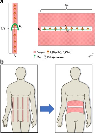
A: Slotted design (right) produces magnetic fields (green arrows) oriented parallel to the slot, while dipoles produce magnetic fields perpendicular to the conductor (left). B: Considering this field orientation, rotation of the slot relative to conventional dipole antenna designs is appropriate for imaging.
Conventional antennas (e.g., dipoles) rely on conductive elements that are often oriented perpendicular to the desired magnetic field, or elements oriented parallel to the z‐direction in MRI (Fig. 1A, left). The z‐oriented currents on the conducting materials produce effective transmit/receive sensitivity 16. In the case of the slot antenna, the slot is parallel to the magnetic field it produces (parallel to the y‐axis in the illustration), which allows for orientation of the length of the slot in the transverse direction. This is beneficial for axial imaging because a single antenna element can provide transmit and receive sensitivity across a broad field of view (FOV). This could simplify conventional z‐oriented coil design by placement and use of a small number of slot antennas around the subject (Fig. 1B). Material on Babinet's Principle and the “duality” between the radiation pattern of slot antennas and that of a corresponding dipole antenna can be found elsewhere 17, 18. Impedance of a slot antenna in air is related to the impedance of the dipole antenna according to:
| (1) |
where is the intrinsic impedance of free space, is the slot antenna impedance and is the impedance of the complementary dipole antenna. Adjustment of the impedance observed at the feed point (related the ratio of E to B, and also to antenna matching in practice) can be achieved by moving the feed point along the slot or by altering the length of the slot aperture 16.
METHODS
Simulations of Single Dipole and Slot Antennas
An 80 × 40 × 80 cm3 rectangular phantom with a relative permittivity of 45.3 and conductivity of 0.33 S/m, representing the average dielectric properties of the body at 7T, was simulated using the Comsol Multiphysics 5.2 (Burlington, MA) finite element modeling (FEM) solver. A slot antenna design was modeled 2 cm above the phantom. A 1 V voltage source was placed across the middle of the slot (Fig. 2A) and tuning was conducted by altering the length of the slot antenna. No additional matching circuits or baluns were used. After tuning, the dimensions of the plate were 45 by 30 cm, and the slot aperture was 45 by 1 cm. A glass‐reinforced epoxy laminate (FR4) substrate was modeled as a 3‐mm‐thick sheet with conductivity of 0.004 S/m and relative permittivity of 4.5. The conductive surface was modeled as perfect electrical conductor (PEC). An adaptable mesh was used to ensure convergence at 300 MHz.
Figure 2.
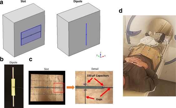
A: Simulation setup of the slot and dipole antenna structures next to a dielectric phantom. Experimental single dipole design (B), slot antenna design (C), and six‐slot array mounted on a subject (D). Narrow gaps with capacitors for blocking low‐frequency gradient‐induced eddy currents are shown in detailed view.
A dipole antenna was modeled 2 cm above a phantom with identical dielectric properties, as in the slot antenna simulations. The conductive surface was modeled as PEC on the substrate of FR4. The dipole was tuned by altering its length, resulting in a dipole 45 cm long and 1 cm wide. A 1 V source across a 10 mm transverse gap bisecting the dipole was used for excitation. The simulation was meshed with an adaptable mesh size ensuring convergence at 300 MHz, and maps of and SAR in the phantom were extracted. The 10g average SAR was computed and power deposition (PD) in the phantom was calculated as in the phantom, where is the conductivity, E is the complex electric field and * indicates the complex conjugate. The maps were normalized by (in the phantom), and the 10g average SAR was scaled to correspond to a field of 2 μT 10 cm into the phantom. An assessment of the planar slot relative to the dipole was conducted by computing the following metrics for the two structures: PD required to produce a 2 μT field 10 cm inside the phantom), maximum 10g average SAR (while producing a 2 μT field 10 cm inside the phantom), central (often called “transmit efficiency”), central (relevant for cases where local SAR is a limiting factor), mean , central SNR, and mean axial and sagittal SNR. Quantitative SNR maps were computed using the method presented in Lattanzi et al. 19.
Numerical Comparison of Dipole and Slot Arrays
The Comsol Multiphysics 5.2 FEM solver was used to model the following coil array arrangements: a four‐channel dipole array, an eight‐channel dipole array, a four‐channel curved slot array, a four‐channel curved slot array where the longitudinal‐oriented edges of the conductive plates are folded away from the phantom and the same four‐channel folded antenna with a length (along z) identical to that of the dipole simulations. The evaluation was conducted to compare the potential performance of slot antenna arrays relative to dipole antenna arrays that are often arranged to encircle the body in high‐field imaging. The arrays were arranged around a cylinder with radius of 20 cm and length of 80 cm. The choice of a 40 cm diameter was chosen as if to accommodate large patients 20 with the coils placed 2 cm away from the phantom surface. The radius of the array was chosen such that imaging of large subject would be possible. Dipole tuning was performed by altering the length of the dipole resulting in a dipole length of 45 cm. For each slot antenna, a plate with arc length of 32 cm and longitudinal dimension of 30 cm contained an aperture of 30 cm by 1 cm.
An additional folded slot antenna was constructed to examine the effects of moving the currents in the longitudinal‐oriented edges of each plate, which run counter to currents in the center of the plate, further from the sample. The folded slot antenna was tuned by altering the size of the antenna, resulting in a slot length of 35 cm along the circumferential section plus 1cm on each of the radial sections for a total slot length of 37 cm. Electrical properties were identical to those of the previously simulated body phantom. To simulate a realistic system environment, the magnet bore was modeled as a cylindrical perfect electrical conductor with a radius of 32 cm concentric with the phantom and coil arrays. Antennas were driven with a 1 V source at 300 MHz. All antenna arrays were driven in “birdcage mode,” with a phase increment from one antenna element to the adjacent element equal to the angle between adjacent elements (i.e., 45 ° phase increment for eight‐element array and 90 ° increment for four‐element arrays). Once the simulations converged, and SAR maps were extracted and 10g average SAR and PD in the phantom was computed. Normalization of the simulations were conducted by scaling the voltage such that a field of 2 μT was produced at the center of the phantom. An assessment of the ‐four dipole, curved slot, and folded curved slot arrays, relative to the eight‐dipole array, was conducted by comparing: PD, maximum 10g average SAR, central , central , mean and SNR. SNR maps were computed using 19.
Phantom Experiments
A dipole antenna having a length (in the longitudinal direction) of 45 cm and a width of 1 cm (Fig. 2B) was constructed from circuit board on an FR4 substrate. Similarly, a slot antenna was fabricated from an 31 mil FR4 board having overall dimensions of 54 cm in length (in the transverse direction) and 30 cm in width (Fig. 2C). The aperture area of the slot was identical to the conductive area of the dipole, 45 cm length (in the transverse direction) and 1 cm width. The lengths of the slot and dipole (45 cm) were determined during tuning, by adjusting the length of the dipole and slot antennas when placed 1 cm above a phantom with an ovular cross section with dimensions of 30 cm (x‐direction) by 20 cm (y‐direction) by 50 cm (z‐direction). The interior of the phantom was composed of corn syrup, water and salt having a conductivity of 0.62 S/m and relative permittivity of 64.5. To minimize potential eddy currents generated by the gradient coils, additional cuts in the conductive plate of the slot antenna were introduced and 28 330 pF capacitors (Model 11331J500WF, Knowles Syfer, Norfolk, UK) were placed across the gaps (red arrows in Figure 2C) to allow high frequency currents to pass while impeding low frequency gradient‐induced eddy currents 21.
Experiments were conducted on a 7T MR system (Siemens Medical Solutions, Erlangen, Germany) in single‐channel transmit mode. The dipole and slot antenna were placed independently 1 cm above the center of the body phantom. For each of the antenna structures, a reference voltage was obtained by adjusting the voltage such that a 90 ° flip angle was produced at a location 2 cm into the phantom from the center of the coil. For each antenna, high‐resolution 2D spoiled axial gradient echo (GRE) images were acquired on the three principal orthogonal planes with 10 ° flip angle, echo time (TE) = 10 ms, repetition time (TR) = 1000, matrix size of 128 × 128, and field of view (FOV) of 300 × 300 mm2. Noise data were acquired with zero transmit voltage to compute the standard deviation of the noise. Flip angle maps were obtained using a presaturation based flip angle mapping technique 22, and SNR maps for the dipole and slot antenna structures were computed using the method of Kellmann and McVeigh 23. Both and SNR maps were plotted for axial and sagittal slices through the center of the phantom and a coronal slice 4 cm inside the body phantom.
In Vivo Experiments
To demonstrate feasibility of the slot antenna for in vivo imaging, first the single slot antenna described above was placed 1 cm above the hip region of a volunteer before running a spoiled axial GRE sequence with 10 ° flip angle, TE = 3.03 ms, TR = 8.6 ms, matrix size of 256 × 256, and FOV of 400 mm × 400 mm for the three principal orthogonal axes. Axial and sagittal images were at the location at the center of the coil, while the coronal slice was localized at the anterior surface of the body, through the femoral head. To investigate the potential to practically use slot antennas in an array, six identical slot antennas were fabricated from 20 cm (transverse direction) by 33 cm FR4 boards with 31 mil thickness, and machining a slot of 18 cm by 1 cm in the middle of the board.
Similar to the single slot antenna, narrow gaps in the conductive plate of the slot antenna were introduced and 330 pF capacitors (Model 11331J500WF, Knowles Syfer, Norfolk, UK) were placed across the gaps. To facilitate practical tuning of these shorter slot antennas, 50 nH solenoid inductors were placed across each end of the slot to increase the effective electrical length of the current path. A matching circuit and cable trap were connected to the driving port of each slot. The six elements were fixed around the pelvis of a volunteer in the 7T system with foam pads approximately 2 cm thick between the subject and each coil (Fig. 2D). Phase‐only shim settings were implemented for imaging the right hip and prostate regions in the volunteer. For each imaging location, images on the three principal orthogonal planes were acquired with a spoiled GRE sequence with 4 ° flip angle, TE = 3.03 ms, TR = 8.6 ms, matrix size of 240 × 240, and FOV of 350 mm × 350 mm.
RESULTS
Simulations
After tuning, S11 of the single planar slot and dipole antennas were ‐18.45 dB and ‐19.6 dB, respectively. After convergence, radiation loss for the slot and dipole antennas was 12.5% and 10% of the total power, respectively. A comparison between simulated dipole and slot antennas is shown in Figure 3, where 10g average SAR (normalized by the voltage required to produce a 2 μT field 10 cm inside the phantom) and (normalized by the square root of PD) of the two antennas was plotted on axial, sagittal, and coronal planes. Plots of , shown in Figure 3A demonstrate that for the dipole antenna large coverage is observed in the longitudinal (z) direction, while for the slot antenna large coverage is observed in the transverse (y) direction, which is beneficial for imaging in transverse planes or imaging ROIs with a larger dimension in the transverse direction. The normalized map for the coronal slice 10 cm inside the phantom for the slot antenna is similar to that of the dipole if rotated 90 °. Line plots along the y‐axis indicate improvement in normalized penetration depth for slot relative to dipoles when the depth is greater than 5.3 cm inside the phantom is shown in Figure 4. Quantitative results comparing the planar slot and dipole are summarized in Table 1.
Figure 3.
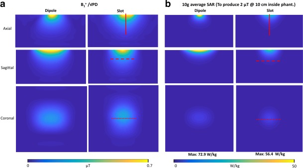
Normalized maps (A) and 10g average SAR maps (B) for axial and sagittal slices at the center of the antenna, and a coronal slice 10 cm inside the phantom.
Figure 4.
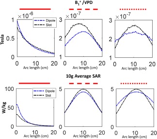
1D projections of the normalized maps and 10g average SAR maps (denoted in red lines in Figure 3) for the slot (black) and dipole (blue) antennas.
Table 1.
Coil Performance Characteristics of the Single Planar Slot Relative to a Dipolea
| Planar dipole | Planar slot | |
|---|---|---|
| PD (W)b | 72.90 | 56.35 (‐22.7%) |
| Max. 10g avg. SAR (W/kg)b | 57.80 | 31.82 (‐44.95%) |
| Central ( ) | 0.23 | 0.27 (+13.7%) |
| Central ( ) | 0.26 | 0.35 (+34.62%) |
| Mean axial ( ) | 0.48 | 0.62 (+29.17%) |
| Mean sagittal ( ) | 0.01 | 0.01 (‐0.61%) |
| Central SNR (a.u.) | 0.23 | 0.27 (+14.82%) |
| Mean axial SNR (a.u.) | 0.48 | 0.62 (+29.06%) |
| Mean sagittal SNR (a.u.) | 0.15 | 0.15 (‐0.61%) |
Numbers in parenthesis indicate percent difference relative to the dipole.
Normalized to produce 2 μT at the center of the phantom.
Multi‐channel Dipole and Slot Array Simulation Results
Multi‐channel coil array structures are shown in Figure 5 (top). Simulation results showed S11 better than ‐12.3 dB for each antenna in the dipole array and maximum coupling (S12) between different dipole antenna elements better than ‐7.8 dB. Similarly, S11 for slot antennas were all <‐9.7 dB and maximum coupling between different slot antenna elements was <‐12 dB. Comparison between the normalized and SNR maps of the four‐channel dipole, eight‐channel dipole, conventional four‐channel slot, folded four‐channel slot and long folded four‐channel slot arrays surrounding the cylindrical phantom is presented in Figure 5. A birdcage‐type excitation pattern was implemented in all simulations to produce optimal constructive interference of at the center of the phantom. Performance of the four antenna arrays in transmission is summarized in Table 2. Results demonstrate lower PD for the slot configurations than the eight‐dipole array. Maximum 10g average SAR is also much lower for the slot antenna arrays. Normalized central , mean normalized in the mid axial plane, and central SNR were higher for the slot antenna arrays than for the dipole arrays. Mean axial SNR for the slotted configurations were greater than for the 4 dipole configuration, but smaller than the eight‐dipole configuration, and mean sagittal SNR was lower in the slot antenna arrays than in the dipole configurations.
Figure 5.
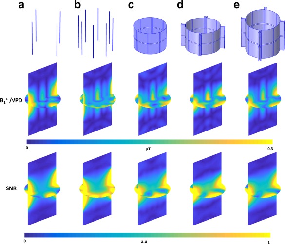
normalized by the square root of PD and SNR computed in the phantom for a four‐element dipole array (A), eight‐element dipole array (B), four‐element encircling slot array (C), four‐element folded slot array (D), and long four‐element folded slot array (E).
Table 2.
Transmit Performance Comparison of Four Dipoles, Curved Slots, Folded Slots, and Long Folded Slots Relative to Eight Dipolesa
| 8 Dipoles | 4 Dipoles | 4 Curved slots | 4 Folded slots | 4 Folded long slots | |
|---|---|---|---|---|---|
| PD (W)b | 83.200 | 133.96 (+61.01%) | 70.4 (‐15.38%) | 50.15 (‐39.72%) | 78.88 (‐5.19%) |
| Max. 10g avg. SAR (W/kg)b | 7.290 | 7.08 (‐2.88%) | 2.38 (‐67.35%) | 2.11 (‐71.06%) | 2.77 (‐62%) |
| Central ( ) | 0.219 | 0.17 (‐21.15%) | 0.24 (+8.74%) | 0.28 (+28.87%) | 0.23 (+2.76%) |
| Central ( ) | 0.741 | 0.75 (+1.43%) | 1.3 (+75.04%) | 1.38 (+85.68%) | 1.2 (+62.24%) |
| Mean axial ( ) | 0.144 | 0.14 (‐3.09%) | 0.16 (+11.06%) | 0.19 (+30.38%) | 0.15 (+6.92%) |
| Mean sagittal ( ) | 0.069 | 0.07 (‐3.13%) | 0.07 (‐3.71%) | 0.06 (‐8.24%) | 0.07 (‐2.34%) |
| Central SNR (a.u.) | 0.077 | 0.1 (+26.76%) | 0.11 (+38.12%) | 0.13 (+63.58%) | 0.1 (+29.77%) |
| Mean axial SNR (a.u.) | 0.144 | 0.1 (‐29.24%) | 0.11 (‐21.97%) | 0.13 (‐10.26%) | 0.11 (‐24.88%) |
| Mean sagittal SNR (a.u.) | 0.080 | 0.07 (‐17.19%) | 0.06 (‐27.1%) | 0.05 (‐31.37%) | 0.06 (‐25.35%) |
Numbers in parenthesis indicate percent difference relative to the eight‐dipole array.
Normalized to produce 2 μT at the center of the phantom.
Phantom and In Vivo Experiments
Adjustment of the length of the slot and dipole antenna tuned the resonator such that S11 was smaller than ‐10 dB (for single and multi‐channel coils), when placed 1 cm above the phantom. The unloaded‐to‐loaded Q ratio of the dipole and slot antennas were 4 and 5.25, respectively. For the experiments, a reference voltage of 145 V was found to produce a 90 ° flip angle at 10 cm into the phantom for both the slot and dipole antennas. Figure 6 shows SNR maps and flip angle maps on the three principal orthogonal planes, while line plots in three principle axes delineated by the red lines in Figure 6 are shown in supplemental materials (see Supporting Figure S1, which is available online). Results demonstrate that the slot antenna produces higher SNR (normalized by the flip angle) and flip angles in deeper tissues as shown by the line‐graphs.
Figure 6.
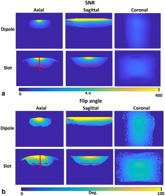
Experimental SNR (A) and flip angle (B) maps in axial, sagittal, and coronal planes for a dipole and slot antennas, placed on top of a body phantom.
Because the of the slot antenna is concentrated in the axial plane, it produces better average SNR and flip angles for axial slices. Furthermore, while a relative reduction in coverage is observed in the longitudinal (z) direction as seen in the sagittal slice of the dipole images, regions of high and SNR extend roughly 20 cm along the z‐axis. In Figure 7 (top), 2D spoiled GRE images are shown for the hip region of a volunteer using a single slot antenna in both transmission and reception. Although the results are preliminary and no optimization was conducted on the slot antenna structure, good sensitivity is observed over a large ROI using a single planar coil. Feasibility of a six‐channel slot antenna array results are shown in the bottom two rows of Figure 7, illustrating the capability to image deep tissues such as the hip and prostate regions, while allowing better coverage and flexibility compared with the single slot design.
Figure 7.
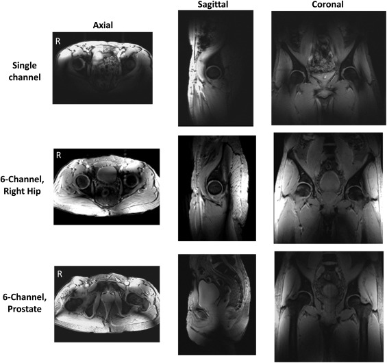
Imaging results on the hip region of a volunteer using a single experimental slot antenna (top row), and array of six slots with phase‐only shim on right hip (middle row) and prostate (bottom row). Axial, sagittal, and coronal slices acquired using a 2D spoiled GRE sequence are shown.
DISCUSSION
Use of electrically long transverse slots introduced in this work, demonstrating a coil structure advantageous for imaging in transverse planes or in ROIs with a larger transverse dimension than longitudinal dimension. Simulation demonstrated that a slot antenna generates improved deep tissue transmit efficiency compared with a long single dipole element, with greater uniformity in the transverse direction and lower uniformity in the longitudinal direction with reduction in maximum 10g average SAR. Longitudinal coverage of the slot antenna was shorter than that of dipole antennas, which may be beneficial for imaging because the B0 homogeneity region in the z‐direction is often smaller than the dimensions of dipoles. In the case of dipoles, E fields often extend outside the imaging volume 24, 25.
Conversely, slots are capable of exciting a narrower ROI close to the isocenter. The concentrated RF field in the limited longitudinal direction improves transmit performance for ROIs near the center of the system. The increase of the slot antenna efficiency can also be explained by the fact that the slot antenna has a more distributed current density. Just as two antennas each driven with 1 W of power can reach higher transmit efficiencies compared with one antenna driven with 2 W. Thus, a more distributed current density resembles the distribution of power over several antenna elements yielding higher efficiency.
Prior studies examined the effects of dipole length on SNR and transmit efficiency 26, 27, indicating an optimal length shorter than the half‐wavelength dipoles modeled here. However, reducing the length of dipoles may necessitate introduction of meanders or other lossy elements that can reduce coil performance. In this work, the long folded slot array extended better coverage in the z direction closer to conventional dipoles, while exhibiting a slight reduction in central SNR and . Control of the transmit and receive sensitivity in the z direction for the slot antenna was obtained by changing the extent of the conductive plate in the z direction with no need to re‐tune. A reason for the good performance of slots relative can be ascribed to the displacement and/or corresponding conductive currents, which in the case of the slot antenna are more distributed than for dipoles.
The highly distributed currents allow closer approximation of the ideal current distributions needed to produce a desirable excitation inside a phantom. Studies on ideal current patterns at for a body‐size cylindrical phantom at 300 MHz have shown that optimal SNR at the center of a cylindrical dielectric sample is achieved using distributed Z‐oriented current patterns rotating at the Larmor frequency 19, 28. In principle, these current patterns could be approximated using a large number of independent dipoles distributed around the imaging subject. This is contrary to the more practical and typical use of a few discrete conductive elements, which concentrate the current patterns to the relatively narrow conductors. The ideal current patterns on a surface 5 mm outside of a cylindrical sample with radius of 20 cm 19, 28 and electrical properties of a phantom identical to that in the slot and dipole simulations is plotted in Figure 8 (top) and compared with the current distribution in the curved slot array in (2nd from top), eight‐channel dipole array (2nd from bottom), and four‐channel dipole array (bottom).
Figure 8.
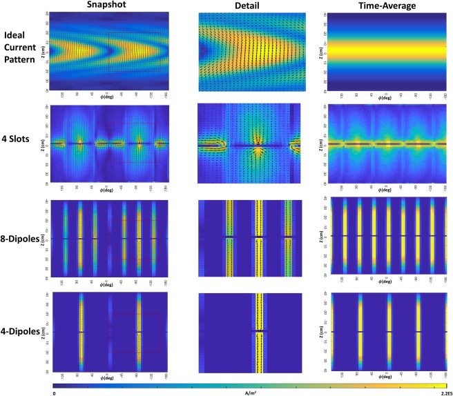
Ideal current patterns (snapshot and time average) around a cylindrical sample (top row), Currents on the conductive surface for a four‐element slot array (2nd row), eight‐element dipole array (3rd row), and four‐element dipole array (bottom row).
Simulations indicate that arranging slots around the body can produce a more efficient central excitation and receive sensitivity relative to four‐ and eight‐channel arrays of long dipole elements positioned around the cylinder. An improvement in field homogeneity of the conventional slot array was achieved by introducing a folded‐slot antenna design, where the longitudinally oriented edges (which carry currents opposite those near the center of the plate) were positioned further from the phantom. This resulted in a more homogeneous and SNR compared with the original curved slot array, as illustrated in Figure 5. Other antenna array designs may have further improved receive/transmit sensitivity relative to the dipole antenna design that was used for comparison here. Nonetheless, it was our intention here to introduce this novel antenna concept rather than fabricate a fully optimized coil.
In future designs, it should be possible to explore several other antenna designs such as: curvature of the slot antenna to match the curvature of the body, arranging slot antennas in the z‐direction, optimizing longitudinal dimensions of the conductive plates, and combining slots and other coil types (e.g., loop arrays or dipoles) for improved SNR and coverage. Furthermore, arrangements where a slotted antenna array design can be integrated into conventional gradient coils can be envisioned. For the in vivo imaging results shown, a flat surface slot antenna was placed on the top of the hip region of a volunteer. While regions of low signal were observed, the single slot antenna illuminated roughly half of the field of view, while the transmit voltage required for excitation was identical to that of a dipole antenna as observed in the phantom experiments. To improve the quality of the in vivo images and enable the capability for transmit shimming, a six‐slot array was constructed and imaging of the hip and prostate region of a volunteer were provided while getting rid of transmit nulls at the region of interest. While this example is far from optimal, it illustrates a proof‐of‐principle into the use of slots as part of an array design showing good sensitivity in deep regions as supported by the simulations.
Because of the large coverage in the transverse direction, it is expected that a smaller number of slot antenna elements can be needed for imaging. Fewer transmit elements would be advantageous to manufacture, and would reduce MR hardware system requirements. However, fewer antenna elements can reduce parallel imaging capabilities in the x–y direction. The ability to place fewer transmit elements can also reduce the flexibility for transmit field shimming. Generally, the azimuthal length of the slot (in the transverse direction) does not allow large number of coil elements to be placed around the human body, which can reduce the degree of freedom. In the case of the six‐channel slot array, inductors bridging the ends of the slot were added to increase the electrical length of the slot azimuthally, while allowing placement of a greater number of elements around the body. Reduction of antenna length could likely be accomplished with introduction of various dielectric substrates to shorten the wavelength in the vicinity of the slot. Further investigation is needed to study the tradeoffs between reducing azimuthal length and increasing the number of elements of the array.
While the slot antennas used here were not optimized for generalized body imaging, this will be the object of future investigation. The fabrication of the experimental slot antenna evaluated in this work was accomplished using conventional FR4 printed circuit board and standard routing machines that were used to etch gaps in the conductors. In practice, positioning of the coil close to the surface of the phantom brought the impedance of the coil close to 50Ω, as observed by the S11 measurements. When the slot design is lifted away from the body, the intrinsic impedance of the coil is changed. Two possible options can be used for matching. The first would be introducing a matching network at the port of the coil using conventional matching circuit designs (as in the six‐channel experiment) 29. The second option is to shift the port location away from the center of the slot. Shifting of the location of the port reduces the impedance of the coil 16, however, it may also change the and distributions generated by the coil. Impedance matching techniques and their effect on sensitivity warrant investigation on a case‐by‐case basis.
CONCLUSIONS
A novel concept for MRI coils based on a transverse slot is introduced here. Simulations and experiments demonstrate improved axial coverage, penetration depth, and efficiency with reduced SAR compared with a dipole antenna.
Supporting information
Fig. S1. 1D projections of the SNR and flip angle maps (denoted in red lines shown in Figure 6) for the experimental single slot (black) and dipole (blue) antennas.
ACKNOWLEDGMENTS
We thank the late Dr. Graham Wiggins for discussions on the correspondence of electrical currents of the slot antenna with the ideal current patterns work. We also thank Jan Paska for his assistance in subject scanning.
Research was supported by NIH grants.
Cofounders of RF Test Labs
REFERENCES
- 1. Vaughan JT, Snyder CJ, DelaBarre LJ, Bolar PJ, Tian J, Bolinger L, Adriany G, Andersen P, Strupp J, Ugurbil K. 7 T whole body imaging: preliminary results. Magn Reson Med 2009;61:244–248. [DOI] [PMC free article] [PubMed] [Google Scholar]
- 2. Vaughan JT, Garwood M, Collins CM, et al. 7T vs. 4T: RF power, homogeneity, and signal‐to‐noise comparison in head images. Magn Reson Med 2001;46:24–30. [DOI] [PubMed] [Google Scholar]
- 3. Hassan A, Elabyed I. Optimal geometry and capacitors distribution of 7T MRI surface coils. In Proceedings of the 40th European Microwave Conference, 2010. pp. 1437–1440.
- 4. Brown R, Storey P, Geppert C, McGorty K, Klautau Leite AP, Babb J, Sodickson DK, Wiggins GC, Moy L. Breast MRI at 7 Tesla with a bilateral coil and robust fat suppression. J Magn Reson Imaging 2014;39:540–549. [DOI] [PMC free article] [PubMed] [Google Scholar]
- 5. Vossen M, Teeuwisse W, Reijnierse M, Collins CM, Smith NB, Webb AG. A radiofrequency coil configuration for imaging the human vertebral column at 7 T. J Magn Reson 2011;208:291–297. [DOI] [PMC free article] [PubMed] [Google Scholar]
- 6. Dieringer MA, Renz W, Lindel T, et al. Design and application of a four‐channel transmit/receive surface coil for functional cardiac imaging at 7T. J Magn Reson Imaging 2011;33:736–741. [DOI] [PubMed] [Google Scholar]
- 7. Raaijmakers AJE, Ipek O, Klomp DWJ, Possanzini C, Harvey PR, Lagendijk JJW, Van Den Berg CAT. Design of a radiative surface coil array element at 7 T: the single‐side adapted dipole antenna. Magn Reson Med 2011;66:1488–1497. [DOI] [PubMed] [Google Scholar]
- 8. Lattanzi R, Sodickson DK, Grant AK, Zhu Y. Electrodynamic constraints on homogeneity and radiofrequency power deposition in multiple coil excitations. Magn Reson Med 2009;61:315–334. [DOI] [PMC free article] [PubMed] [Google Scholar]
- 9. Lattanzi R, Sodickson DK. Ideal current patterns yielding optimal SNR and SAR in magnetic resonance imaging: computational methods and physical insights. Magn Reson Med 2013;68:286–304. [DOI] [PMC free article] [PubMed] [Google Scholar]
- 10. Duan Q, Nair G, Gudino N, De Zwart JA, Van Gelderen P, Murphy‐Boesch J, Reich DS, Duyn JH, Merkle H. A 7T spine array based on electric dipole transmitters. Magn Reson Med 2015;74:1189–1197. [DOI] [PMC free article] [PubMed] [Google Scholar]
- 11. Erturk MA, Raaijmakers AJE, Adriany G, Ugurbil K, Metzger GJ. A 16‐channel combined loop‐dipole transceiver array for 7 Tesla body MRI. Magn Reson Med 2017;77:884–894. [DOI] [PMC free article] [PubMed] [Google Scholar]
- 12. Chen G, Cloos M, Sodickson DK, Wiggins G. A 7T 8 channel transmit‐receive dipole array for head imaging: dipole element and coil evaluation. In Proceedings of the 22nd Annual Meeting of ISMRM, Milan, Italy, 2014. Abstract 4572.
- 13. Lee W, Cloos M, York N, States U. Parallel transceiver array design using the modified folded dipole for 7T body applications. In Proceedings of the 21st Annual Meeting of ISMRM, Salt Lake City, Utah, USA, 2013. Abstract 0292.
- 14. Hong SM, Park JH, Woo MK, Kim YB, Cho ZH. New design concept of monopole antenna array for UHF 7T MRI. Magn Reson Med 2014;71:1944–1952. [DOI] [PubMed] [Google Scholar]
- 15. Brunner DO, De Zanche N, Fröhlich J, Paska J, Pruessmann KP. Travelling‐wave nuclear magnetic resonance. Nature 2009;457:994–998. [DOI] [PubMed] [Google Scholar]
- 16. Kraus JD, Marhefka RJ. Antennas for all applications. New York: McGraw‐Hill; 2002. p 304. [Google Scholar]
- 17. Baum C, Singaraju B. Generalization of Babinet's principle in terms of the combined field to include impedance loaded aperture antennas and scatterers. In Antennas and Propagation Society International Symposium, Urbana, Illinois, USA, 1975.
- 18. Jackson JD. Classical electrodynamics. Am J Phys 1999;67:841. [Google Scholar]
- 19. Lattanzi R, Grant A, Sodickson D. Approaching ultimate SNR and ideal current patterns with finite surface coil arrays on a dielectric cylinder. In Proceedings of the 16th Annual Meeting of ISMRM, Toronto, Canada, 2008. Abstract 1074.
- 20. Flegal KM. Waist circumference of healthy men and women in the United States. Int J Obes 2007;31:1134–1139. [DOI] [PubMed] [Google Scholar]
- 21. Alecci M, Jezzard P. Characterization and reduction of gradient‐induced eddy currents in the RF shield of a TEM resonator. Magn Reson Med 2002;48:404–407. [DOI] [PubMed] [Google Scholar]
- 22. Fautz H, Vogel M, Gross P. B1 mapping of coil arrays for parallel transmission. In Proceedings of the 16th Annual Meeting of ISMRM, Toronto, Canada, 2008. Abstract 1247.
- 23. Kellman P, McVeigh ER. Image reconstruction in SNR units: a general method for SNR measurement. Magn Reson Med 2005;54:1439–1447. [DOI] [PMC free article] [PubMed] [Google Scholar]
- 24. Ugurbil K. Magnetic resonance imaging at ultrahigh fields. IEEE Trans Biomed Eng 2014;61:1364–1379. [DOI] [PMC free article] [PubMed] [Google Scholar]
- 25. Robitaille P‐M, Berliner LJ. Ultra high field magnetic resonance imaging. New York: Springer Science & Business Media; 2006. [Google Scholar]
- 26. Raaijmakers AJE, Italiaander M, Voogt IJ, Luijten PR, Hoogduin JM, Klomp DWJ, van den Berg CAT. The fractionated dipole antenna: a new antenna for body imaging at 7 Tesla. Magn Reson Med 2015;1374:1366–1374. [DOI] [PubMed] [Google Scholar]
- 27. Wiggins GC, Zhang B, Lattanzi R, Chen G, Sodickson DK. The electric dipole array: an attempt to match the ideal current pattern for central SNR at 7 Tesla. In Proceedings of the 20th Annual Meeting of ISMRM, Melbourne, Australia, 2012. Abstract 541.
- 28. Lattanzi R, Grant AK, Polimeni JR, Ohliger MA, Wiggins GC, Wald LL, Sodickson DK. Performance evaluation of a 32‐element head array with respect to the ultimate intrinsic SNR. NMR Biomed 2010;23:142–151. [DOI] [PMC free article] [PubMed] [Google Scholar]
- 29. Peterson DM. Impedance matching and baluns In: Vaughan TJ, Griffiths JR, editors. RF coils for MRI. New York: Wiley; 2012. p 315. [Google Scholar]
Associated Data
This section collects any data citations, data availability statements, or supplementary materials included in this article.
Supplementary Materials
Fig. S1. 1D projections of the SNR and flip angle maps (denoted in red lines shown in Figure 6) for the experimental single slot (black) and dipole (blue) antennas.


