Abstract
Acceleration and manipulation of electron bunches underlie most electron and X-ray devices used for ultrafast imaging and spectroscopy. New terahertz-driven concepts offer orders-of-magnitude improvements in field strengths, field gradients, laser synchronization and compactness relative to conventional radio-frequency devices, enabling shorter electron bunches and higher resolution with less infrastructure while maintaining high charge capacities (pC), repetition rates (kHz) and stability. We present a segmented terahertz electron accelerator and manipulator (STEAM) capable of performing multiple high-field operations on the 6D-phase-space of ultrashort electron bunches. With this single device, powered by few-micro-Joule, single-cycle, 0.3 THz pulses, we demonstrate record THz-acceleration of >30 keV, streaking with <10 fs resolution, focusing with >2 kT/m strength, compression to ~100 fs as well as real-time switching between these modes of operation. The STEAM device demonstrates the feasibility of THz-based electron accelerators, manipulators and diagnostic tools enabling science beyond current resolution frontiers with transformative impact.
Particle accelerator development over the last century has underpinned the study of fundamental forces and particles as well as structure and function of materials and its properties at ever higher spatial and temporal resolution. Until recently, microwaves in the radio-frequency (RF) regime (1-10 GHz) have been the conventional choice for powering accelerators due to the high degree of technical maturity of the sources which have been used extensively across all areas of industry and science, from cell phones, microwave ovens and radar to linear accelerators1, bunch compressors2,3 and high-resolution streak cameras4,5. The long driver wavelengths are ideal for accelerating electron bunches with up to nanocoulomb bunch charge, and as a result of many decades of development, it has become possible to generate ultrafast electron pulses with very high peak brightness and quality. However, RF-based accelerators require costly infrastructures of large size and power6, limiting the availability of this key scientific resource. They also suffer from inherent difficulties in synchronization with lasers7 which lead to timing drifts on the 100-femtosecond scale between the electrons, microwave drivers and optical probes, limiting the achievable temporal resolution. Strong motivation thus exists for exploring alternative technologies that are compact, more accessible and adapted for pushing the resolution frontier especially where lower levels of charge in the few pC range or lower is sufficient. Novel accelerator concepts thus primarily focus on laser-based approaches that provide intrinsic synchronization, allow scaling to smaller accelerator structures and can generate substantially stronger fields for acceleration and beam manipulation. These include dielectric laser accelerators (DLAs)8,9, laser-plasma accelerators (LPAs)10–14 and laser-based THz-driven accelerators15–17, each with different advantages. A consequence of downscaling in size is that less charge can be supported and creation of reliable structures can become more difficult. LPAs, for example, which boast extremely high acceleration gradients on the order of 100 GV/m, generate acceleration structures dynamically and therefore suffer from instabilities and difficulties in controlling injection. DLAs, which employ micron-scale structures, require extreme tolerances on alignment and control, and are limited to bunch charges in the sub-femtocoulomb range. THz-based accelerators, however, exist at an intermediate, millimeter scale that allows traditional fabrication techniques and supports moderate charge while still benefiting from compactness, low cost and strong driving fields. This balance makes THz-based acceleration an extremely promising technology for future devices.
So far, the development of THz-based accelerators has been limited by the lack of sufficiently energetic THz sources, but recent progress in efficient laser-based methods18–20 has enabled generation of high-power, GV/m THz fields, opening new possibilities and spurring interest in THz-accelerator-related technologies. Proof-of-principle demonstrations include electron emission21,22 and acceleration15,16,23–27 as well as compression and streaking28,29. These experiments, although limited in charge, beam quality, energy gain and energy spread, have set the stage for development of practical, compact THz-based devices which can support sufficient charge and field gradients to realistically be used to boost performance of existing accelerators or as components of future compact accelerators and X-ray sources. In this letter, we demonstrate the first such device based on a layered, transversely pumped, waveguide structure. This segmented THz electron accelerator and manipulator (STEAM) device can dynamically switch between accelerating, streaking, focusing and compressing modes, can support multiple picocoulombs of charge and features intrinsic synchronization. Using only a few microjoules of single-cycle THz radiation, we demonstrate over 70 MV/m peak acceleration fields, 2 kT/m focusing gradients (which are an order of magnitude beyond current electromagnetic lenses and comparable to active plasma lenses), the highest reported THz streaking gradient of 140 µrad/fs (making it well-suited for characterization of ultrafast electron diffractometer bunches down to 10 fs) as well as compression to ~100 fs. All these demonstrations are strongly benefitting from very small temporal jitter achieved through laser-driven THz sources (see supplementary material). By increasing THz pulse energies to state-of-the-art millijoule levels20, it is expected that acceleration gradients approaching 1 GV/m can be achieved and sustained. Such gradients surpass those possible in RF accelerators by an order of magnitude and enable major improvements in electron bunch qualities such as emittance and bunch length. The picosecond duration of the THz pulses is an essential ingredient for reaching the GV/m regime, since experiments have shown that maximum acceleration gradients, which are limited by field-induced breakdown, scale with the sixth power of the field duration30–33. Demonstration of the THz-driven STEAM device thus establishes a new compact, strong-field and extremely-high-gradient accelerator technology.
Concept and implementation
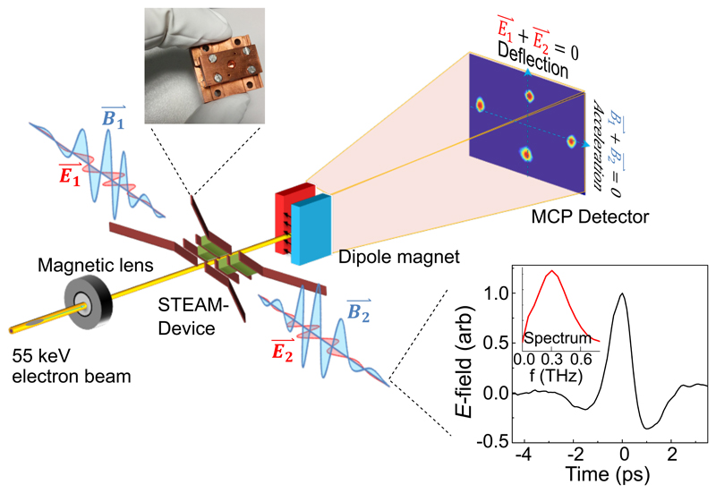
The experimental setup (Fig. 1a) consisted of a 55 keV photo-triggered DC gun, a THz-powered STEAM device for electron acceleration or manipulation and a diagnostic section which included a second STEAM device used as a streak camera, all of which were driven by the same IR laser source. Ultraviolet pulses for photoemission were generated by two successive stages of second harmonic generation, while single-cycle THz pulses were generated by difference frequency generation. THz from two independent setups was coupled into the STEAM device (Fig. 1c) transversely to the electron motion by two horn structures which focused the counter-propagating THz fields beyond the diffraction limit into the interaction zone. The electrons experience both the electric and magnetic fields of the THz pulses according to the Lorentz force law where -q is the electron charge, is the electric field, oriented parallel to the electron velocity , and is the magnetic field, oriented vertically in the lab frame. The electric field is thus responsible for acceleration and deceleration, while the magnetic field induces transverse deflections.
Fig. 1. Experimental setup.
Schematic illustration of the experimental setup. A fraction of the infrared optical beam is converted to 257 nm through fourth harmonic generation. The 257 nm laser pulse is directed onto a gold photocathode generating electron pulses, which are accelerated to 55 keV by a DC electric field. This laser also drives two optical-rectification stages, each generating single-cycle terahertz pulses with energy up to 30 µJ. The two counter-propagating THz beams interact with the electron beam inside the segmented structure. Subsequently, the electron beam is detected by the camera. Inset: Top Left: photograph of the STEAM device; Bottom right: The time-domain waveform of the THz pulse measured by electro-optic sampling and its corresponding frequency-domain spectrum.
Efficient interaction of the electrons with the fields was accomplished by means of segmentation which divided the interaction volume into multiple layers, each isolated from the others by thin metal sheets (Fig. 1a). Dielectric slabs of varying length were inserted into each layer to delay the arrival time of the THz waveform to coincide with the arrival of the electrons, effectively phase-matching the interaction. Due to the transverse geometry, the degree of dephasing experienced in each layer was determined by the traversal time of the electrons, which was dependent on the electron speed and the layer thickness. A reduction in dephasing can thus be accomplished by reducing the layer thickness and increasing the number of layers, at the cost of increased complexity. The ability to tune the thickness and delay of each layer independently is a key design feature of the STEAM device that enables acceleration of sub-relativistic electrons for which the speed changes significantly during the interaction (e.g, from 0.43 c to 0.51 c for our maximum acceleration case).
The use of two counter-propagating drive pulses enabled two key modes of operation which are specified with respect to the interaction point, i.e., the center of the interaction region of each layer:
an “electric” mode, used for acceleration, compression & focusing, in which the pulses were timed to produce electric superposition and magnetic cancellation of the transverse fields at the interaction point;
a “magnetic” mode, used for deflection and streaking, where the magnetic fields superposed and the electric fields cancelled.
The function of the device was thus selected by tuning the relative delay of the two THz pulses and the electrons, all of which were controlled by means of motorized stages acting on the respective IR pump beams. In focusing and streaking modes the electron beams were sent directly to a MCP-detector. For acceleration measurements, an electromagnetic dipole was used to induce energy-dependent deflections in the vertical plane, so that both deflection and energy change could be measured simultaneously. To measure the compression, a second STEAM device in streaking mode was added downstream of the first to induce time-dependent deflections in the horizontal plane. The breakdown threshold of the device is determined by field emission from the metallic parts. Owing to the 4-5 orders of magnitude shorter field-exposure times of single-cycle THz pulses as compared with RF excitations, the previous studies suggest that a factor of 3-10 higher breakdown threshold for pulsed THz driven devices can be expected26,31. The remainder of this paper gives a detailed description of the results obtained for acceleration, compression, focusing, deflection and streaking for this STEAM device.
Electric Mode: acceleration, compression & focusing
In the electric mode, the relative timing of the THz pulses was adjusted so that the electric fields (E-fields) constructively interfered at the interaction point. In this configuration, the magnetic fields (B-fields) were 180° out of phase with each other and thus cancelled, minimizing unwanted deflections. The acceleration was sensitive to the THz phase at the interaction. Figure 2 shows energy and deflection diagrams which were obtained by recording the vertical and horizontal projections (respectively) of the electron-beam distribution on the MCP as a function of the electron-THz delay. Although the THz pulses injected into the device were nearly single cycle, several cycles of acceleration and deceleration were observed, due to dispersion induced by the horn couplers.
Fig. 2. Concept and implementation.
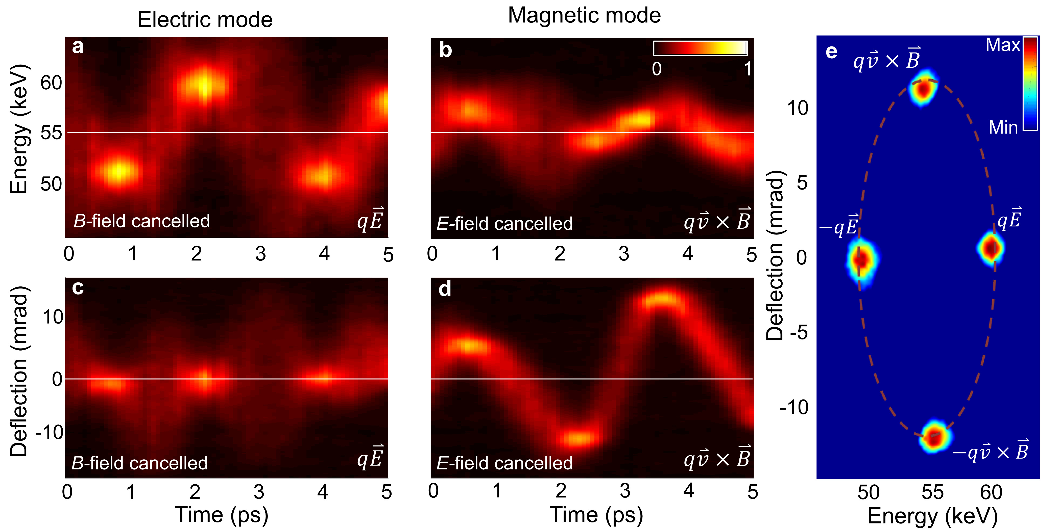
a, Measured energy modulation of e-pulse as a function of electron-THz delay for constructive interference of the E-fields entering the device and cancellation of B-fields. b, Corresponding beam deflection measured for constructively interfering of the B-fields, i.e. E-field cancellation scenario. (c) and (d): Time-dependent deflection diagram measured by varying the electron-THz delay in the B-field and E-field cancellation scenario, respectively. e, Measured shape of e-beam on MCP detector for maximum acceleration, deceleration and right and left deflection points plotted in one image. Intensity was normalized and image contrast was tuned in order to show the relative positions more clearly. This demonstration was performed using the Yb:KYW laser with ~2×0.5 µJ of THz radiation coupled into the device and a bunch charge of ~1 fC.
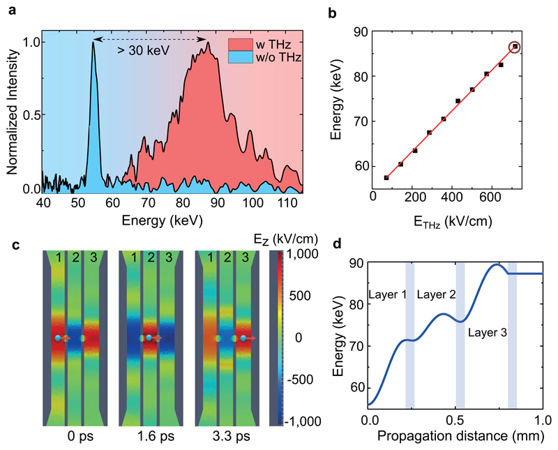
Maximum acceleration and deceleration occurred at the electron injection points (Fig. 2a) where the deflection was minimized (Fig. 2c) and the beam spatial distribution was also preserved (Fig. 2e left & right beams). The peak field is calculated to have reached ~70 MV/m with the Yb:YLF laser, based on comparisons of the measured THz energy transmitted through the device and the electron energy gain with simulation (described below). The energy gain scaled linearly with the applied field (Fig. 3b) and reached a record of more than 30 keV (5 times larger than previous works15) for a bunch charge of ~5 fC. In contrast to previous results showing simultaneous acceleration and deceleration, the energy spectrum can be seen to move cleanly to a higher energy (Fig. 3a), indicating that injected bunches were shorter than half the driver period. In fact, the bunches were measured (by the STEAM device in streaking mode) to have a duration of 670 fs, and thus occupied about 20% of the 3.33 ps period accelerating field. The increase in energy spread is attributed in part to the variation of the E-field over the bunch temporal profile. Although bunches with charge up to 20 fC were coupled into the device, space-charge effects and the long travel distances from the DC gun lead to longer bunch duration and larger energy spread. For demonstrating THz-driven acceleration, the charge was limited to 1-5 fC during this experiment. Use of a THz-based re-buncher before the accelerator is thus anticipated for future experiments to reduce energy spread.
Fig. 3. Terahertz acceleration.
a, Measured electron energy spectra for input beam (blue curve) and accelerated beam (red curve) after the STEAM-device that shows an energy gain of more than 30 keV. An increased energy spread is observed due to the long length of the initial electron bunch, as well as the slippage between the THz pulse and the electron bunch. b, Relative energy versus input terahertz field strength with red circle indicating the energy spectra plotted in (a) The linear relationship supports a direct, field-driven interaction. c, Temporal evolution of the electric field inside each layer with the red arrow indicating the electron propagating. d, Calculated acceleration along the electron propagation direction with ~2×6 µJ THz and beam diameter of 3 mm. This illustration was performed for the experiment using the Yb:YLF laser with ~2×6 µJ THz radiation coupled into the device and a bunch charge of ~5 fC.
The performance of the device was simulated using a finite-element based code34. Figure 3c shows snapshots of the electrons traversing the device and staying in phase with the field (full simulation results are presented in movie S1). Figure 3d shows the electron energy as a function of distance. The energy gain can be seen to occur in three uneven steps corresponding to the three layers. The unevenness and the presence of deceleration at some points are evidence of dephasing due to the fact that the structure was designed for higher THz energies (see supplementary material). Simulations predict that MeV electron beams with up to 10 pC of charge are achievable by increasing the number of layers and extending THz pulse energies to the millijoule level24 which is within the reach of current THz-generation methods20.
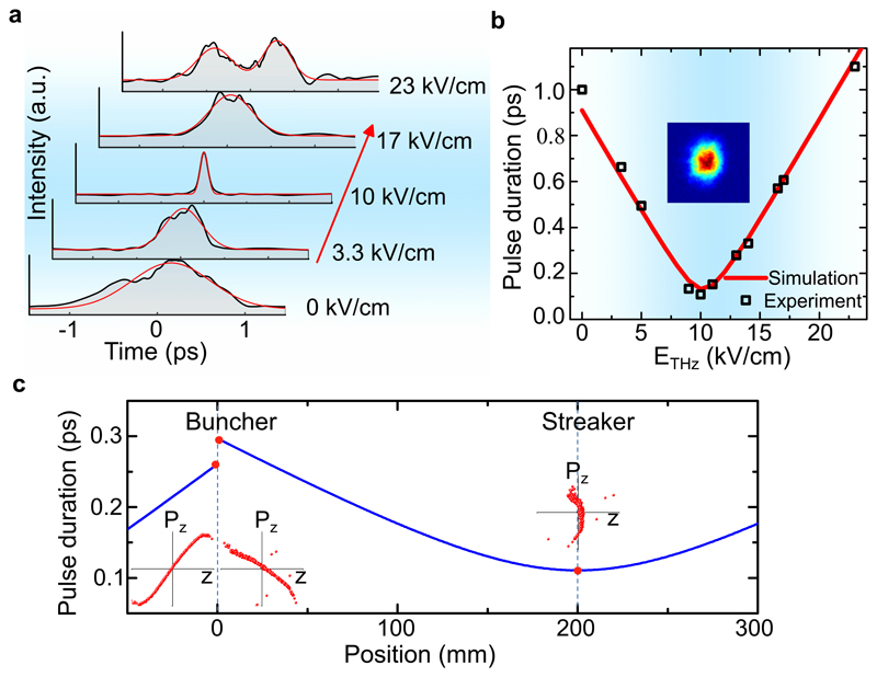
At timings off from the optimum acceleration, the electrons experienced strong temporal gradients of the E-field resulting in large energy spreads (Fig. 2a). At the zero-crossing of the field, the gradient is maximized and the electrons see symmetric acceleration and deceleration but no net energy gain. In this mode, the E-field imparts a temporally-varying energy or “chirp” resulting in a velocity gradient that causes either compression or stretching (depending on the sign of the gradient) of the electron bunch as it propagates35. This technique, known as “velocity bunching” is an ideal application of THz technology, since the sub-mm-scale gradients allow bunch compression down to the femtosecond range. To test this concept, the applied THz energy was varied and a second STEAM device (“streaker”) acting as a streak camera (described in the next section) was added to measure the bunch temporal profile at a point 200 mm downstream of the first device (“buncher”).
Figure 4a shows the electron bunch temporal profiles measured at the streaker for various field strengths applied to the buncher. The initial decrease in bunch duration with increasing field confirms that the electrons arrive at the buncher with a space-charge-induced energy chirp. A minimum duration of ~100 fs FWHM was achieved after which the duration increases again (Fig. 4b), implying that for high fields the electrons temporally focus before the streaker and are over compressed by the time they are measured. The minimum bunch duration can thus be reduced by using stronger fields and a shorter propagation distance as shown by the simulation in Supplementary Fig. S7. As observed on the MCP-detector (Fig. 4b inset), a good e-beam profile is maintained at the optimal compressed condition. Figure 4c shows the evolution of the bunch duration with distance simulated for the minimum bunch duration case. The phase-space distributions in insets d, e & f show the reversal of the velocity correlation by the buncher and the eventual compression at the streaker location.
Fig. 4. Terahertz-driven electron pulse compression.
a, Measured temporal profiles of the electron pulses as the THz field in the buncher is increased (red arrow). The red lines represent Gaussian fits. b, Black squares: measured electron bunch FWHM duration versus incident THz field strength. Red line: corresponding simulation results. Inset: the electron beam spatial profile on the detector at the optimal compressed condition. c, Simulated bunch length vs position. Inset: longitudinal phase-space distribution before the rebunching cavity, after the rebunching cavity and maximally compressed position marked with red dots respectively. This demonstration was performed with the Yb:KYW laser using one STEAM-device as a rebunching cavity and one as electron streak camera with a bunch charge of ~1 fC.
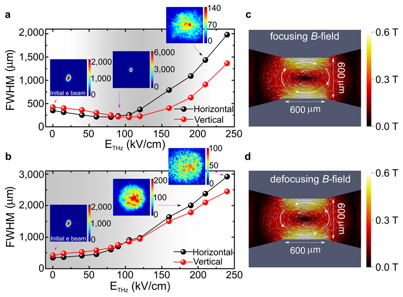
By placing the electrons at the zero crossing in the electric mode (corresponding to the maximum B-field rotating around the interaction region), the STEAM device can also operate as a focusing or defocusing element, as can be seen by the horizontal spreading of the beam profile in Figure 2c. Due to the strong THz field that leads to over-focusing at the fixed MCP position, both focusing and defocusing schemes are observed here as an increase of the beam size. This focusing effect is a consequence of the well-known Panofsky-Wenzel Theorem36 which uses Gauss’s law to show that longitudinal compressing and decompressing fields must be accompanied by transverse defocusing and focusing fields, respectively. The B-field always cancels at the interaction point, while still has time varying transverse magnetic field distribution in the antinode region that contributes to the defocusing and focusing (illustrated in Fig. 5c,d). The focusing was tested by monitoring the beam spatial profile at the MCP for varying THz pulse energies. Figure 5a shows the results for the focusing configuration, which corresponded to the longitudinal decompression condition. At best focusing the electron beam diameter was reduced by 2 × compared to its input value. For higher field strengths, however, the device focal length became shorter than the 180 mm distance to the MCP, causing the measured beam size to increase again. Similarly to photon beams, a focusing optics with higher focusing power results in a smaller beam at focus, provided that the input beam size is constant (see supplementary material). The defocusing configuration is obtained by shifting the electron timing to the longitudinal compression condition, which occurs at an adjacent zero crossing of opposite sign. In this case, the electron beam diameter increases monotonically with the THz field (Fig. 5b), as expected. For both cases, the focusing performance is significantly beyond what is offered by conventional electrostatic37 and proposed dielectric focusing structures38 and is comparable to those of plasma lenses39. Peak focusing gradients of >2 kT/m were calculated based on ~2×6 µJ of coupled THz energy. A small (less than a factor of 2) asymmetry is noticeable for the focusing strengths in the horizontal and vertical planes. This asymmetry is due to the asymmetry of the interaction region which leads to stronger gradients in the vertical direction (Fig. 5c,d).
Fig. 5. Terahertz-lens for electron pulse focusing/defocusing.
(a) and (b): Measured transverse electron beam size at the MCP as a function of THz field, respectively. This demonstration was performed with the Yb:KYW laser and a bunch charge of ~1 fC. Insets: spatial profiles of initial and focused and defocused electron beams on the MCP-detector. Legend shows the number of counts on the detector. (c) and (d): Computed spatial field distributions of the focusing and defocusing fields, respectively. Simulation is performed with ~2×6 µJ THz and beam diameter of 3 mm.
Magnetic Mode: Deflection & streaking
In the magnetic mode, the relative timing of the THz fields is different from that of the electric mode by a half period, resulting in reinforcement of the magnetic and cancellation of the electric fields at the interaction region. In this configuration, electron acceleration is minimized (Fig. 2b), and the B-field dominates the interaction causing a transverse deflection of the electron beam that depends on the THz phase at the interaction (Fig. 2d). When electrons sweep the positive cycle of the B-field, the deflection is maximized and the beam profile is also best preserved. In this mode, electron beams can be precisely steered (Fig. 2e top & bottom beams) by varying the THz pulse energy. Here, we achieved continuous control of the beam angle over a range of 70 mrad which was limited by the aperture of the device (Supplementary Fig. S6). Increasing the aperture enables greater range at the cost of a weaker deflection field, since the field confinement is affected.
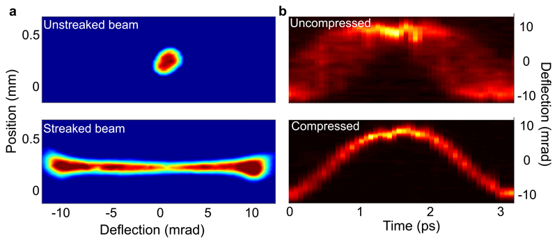
Electrons sweeping the zero crossing cycle of the THz B-field, on the other hand, experience a strong deflection as a function of delay time enabling the measurement of the temporal bunch profiles of very short bunches by mapping (or “streaking”) them onto the spatial dimension of a detector. To test this concept, a first STEAM device was used in compression mode (as described above) to provide electrons of varying bunch durations at a second, downstream STEAM device which analyzed the temporal profiles by streaking. Figure 6a shows raw images of a temporally-long electron beam with the THz streaking field switched on and off. Streaking “deflectograms,” generated by plotting a lineout of the spatial charge distribution along the streaking dimension as a function of delay relative to the THz field, are shown in Fig. 6b for compressed and uncompressed electron bunches. The degree of streaking, indicated by the vertical extent of the deflectogram, depends clearly on the bunch duration and on the phase of the THz field, as expected. For a THz energy of ~2×6 μJ coupled into the device, a maximum deflection rate of > 140 µrad/fs was achieved (Supplementary Fig. S7), corresponding to a temporal resolution below 10 fs. The resolution was limited here by the 350 µm size of the unstreaked beam. These results represent a new record in THz-based streaking gradient as well as the first use of THz B-fields for deflection and streaking.
Fig. 6. Terahertz streak camera.
a, Measured images of the electron beam on the MCP-detector with and without the terahertz deflection field. b, Time-dependent deflection diagram measured by varying the delay between the arrival time of electron bunch and the deflecting terahertz pulse for initially compressed and uncompressed electron bunches. This demonstration was performed with the Yb:KYW laser and a bunch charge of ~1 fC, except for the maximum streaked beam (a), where a bunch charge of ~10 fC is used in order to get a long pulse for demonstration. Deflectograms using the Yb:YLF laser can be found in the supplementary material showing more than 70 mrad deflection.
Conclusions and outlook
We have demonstrated a novel segmented THz electron accelerator and manipulator setting new records in THz acceleration, streaking and focusing with a very compact device. The segmented structure makes it possible to phase-match the electron-THz interaction for non-relativistic beams, making it ideal for use as a high-gradient photogun24. The independent control over the counter-propagating THz pulse timing gives the STEAM device the ability to switch dynamically between acceleration, compression, focusing, deflection and streaking modes. As was theoretically shown in ref. 24, the use of THz pulses also brings other advantages, including negligible heat loads, high repetition rates and compactness while still supporting substantial charge in the pC regime. Furthermore, the three-layer structure demonstrated in this study indicates the path forward towards relativistic electron energies by staging more layers for higher operation efficiency.
Using only ~2×6 µJ of THz energy the STEAM device has demonstrated peak acceleration gradients of 70 MV/m, compression of a bunch from over 1ps to 100 fs, focusing strength of ~2 kT/m and streaking gradients of >140 µrad/fs, leading to a temporal resolution below 10 fs. By scaling to millijoule-level THz energies which are already available in some THz wavelength ranges, the field strengths in the device can be increased by over an order of magnitude far exceeding those of conventional RF devices. The exceptional performance and compactness of this THz-based device makes it very attractive for pursuing electron sources, like ultrafast electron diffractometers, that operate in the few- and sub-fs range necessary for probing the fastest material dynamics40,41. In the pursuit of these sources, the demand is increasing for compact, high-gradient diagnostics and beam manipulation devices for novel and conventional accelerator platforms alike. In large-scale facilities like the European XFEL, LCLS or Swiss FEL, the, STEAM devices can be used to add new, powerful and adaptable capabilities without major and therefore costly restructuring of the machine. More significant are the advantages in terms of cost and accessibility that come from using STEAM devices as the core components of an all-THz-powered compact, high-gradient accelerator with the ability to produce high-quality, controllable bunches of femtosecond or attosecond duration on a table top. The results presented here are the first step in demonstrating the feasibility of that vision.
Methods
Laser systems
Experiments were performed both with a 550fs, 4 mJ, 1,030 nm Yb:KYW laser operating at 1 kHz, to demonstrate high repetition rates, as well as with a 1.1 ps, 40 mJ, 1,020 nm Yb:YLF laser operating at 10 Hz, in order to demonstrate high peak accelerations. Using these systems, THz pulses with a center frequency of 0.3 THz were generated (Fig. 1 inset) by the well-established tilted pulse-front method15 from a LiNbO3 crystal, resulting in 2×2 μJ pulses and 2×30 μJ from the Yb:KYW and Yb:YLF laser systems, respectively (supplementary material). Substantial losses due to transport and coupling of the THz beam, however, resulted in pulse energies at the interaction region of only 2×0.5 µJ and 2×6 µJ for the Yb:KYW and Yb:YLF, respectively. The beam diameter at focus was measured to be 3 mm. This diameter was also used for the corresponding simulations.
STEAM device dimensions
The STEAM device was designed with three layers of thickness h = {0.225, 0.225, 0.250} mm and with dielectric slabs in the second and third layers made of fused silica (ϵr = 4.41) and of length L = {0.42, 0.84} mm. The entrance and exit apertures were of diameter 120 µm. Further design parameters for the structure are shown in Supplementary Fig. S1.
Supplementary Material
Acknowledgments
We gratefully acknowledge helpful discussions with Chun Zhou, Wenqian Ronny Huang, Frederike Ahr, Wenchao Qiao, the expert technical support of Thomas Tilp, and Matthias Schust for fabrication of the STEAM-devices used in this work. Besides Deutsches Elektronen-Synchrotron (DESY) and the Helmholtz Association, this work has been supported by the European Research Council under the European Union’s Seventh Framework Programme (FP7/2007-2013) through the Synergy Grant ‘Frontiers in Attosecond X-ray Science: Imaging and Spectroscopy’ (AXSIS) (609920) and the excellence cluster “The Hamburg Center for Ultrafast Imaging – Structure, Dynamics and Control of Matter at the Atomic Scale” (CUI, DFG-EXC1074), the priority program ‘Quantum Dynamics in Tailored Intense Fields’ (QUTIF) (SPP1840 SOLSTICE) of the Deutsche Forschungsgemeinschaft and the accelerator on a chip program (ACHIP) funded by the Gordon and Betty Moore foundation (GBMF4744). The authors also thank Dr. T. Y. Fan and Dr. J. Zayhowski from MIT Lincoln Laboratory for initial work on the cryogenic Yb:YLF laser within the AXIS Program funded by the Defense Advanced Research Projects Agency (DARPA) and DARPA for the loan of the laser. Xiaojun Wu acknowledges support through Georg Forster Research Fellowship of the Alexander von Humboldt Foundation and Anne-Laure Calendron through a Helmholtz Postdoctoral Fellowship from the Helmholtz Association.
Footnotes
Author contribution
F.X.K., D.Z., A.F. and N.H.M. conceived and coordinate the THz-driven electron acceleration and manipulation project. The structure was designed by A.F. and M.F. D.Z. designed the experimental setup and carried out the experiments. M.H., L.E.Z. and Y.H. built the Yb:YLF laser. A.-L.C. built the Yb:KYW laser with the help of H.C. X.W. and D.Z. built the THz setup. D.Z. built the UV generation and automated the setup. A.F. performed all simulations. A.-L.C., H.C., M.H., Y.H. and L.E.Z. maintained the laser systems and contributed with helpful discussions on the experiment. D.Z., A.F., N.H.M. and F.X.K. wrote the manuscript with revisions by all.
Competing interests
The authors declare no competing financial interests.
Code availability
The code used in this paper is available from the corresponding author upon reasonable request.
Data availability
The data that support the plots within this paper and other findings of this study are available from the corresponding author upon reasonable request.
References
- 1.European X-Ray Free-Electron Laser Facility. https://www.xfel.eu/index_eng.html.
- 2.Gao M, et al. Full characterization of RF compressed femtosecond electron pulses using ponderomotive scattering. Opt Express. 2012;20:12048–12058. doi: 10.1364/OE.20.012048. [DOI] [PubMed] [Google Scholar]
- 3.Maxson J, et al. Direct Measurement of Sub-10 fs Relativistic Electron Beams with Ultralow Emittance. Phys Rev Lett. 2017;118:154802. doi: 10.1103/PhysRevLett.118.154802. [DOI] [PubMed] [Google Scholar]
- 4.Floettmann K, Paramonov VV. Beam dynamics in transverse deflecting rf structures. Phys Rev Accel Beams. 2014;17:024001. [Google Scholar]
- 5.Ischebeck R, Prat E, Thominet V, Loch CO. Transverse profile imager for ultrabright electron beams. Phys Rev Accel Beams. 2015;18:082802. [Google Scholar]
- 6.Manz S, et al. Mapping atomic motions with ultrabright electrons: towards fundamental limits in space-time resolution. Faraday Discuss. 2015;177:467–491. doi: 10.1039/c4fd00204k. [DOI] [PubMed] [Google Scholar]
- 7.Yang H, et al. 10-fs-level synchronization of photocathode laser with RF-oscillator for ultrafast electron and X-ray sources. Sci Rep. 2017;7:39966. doi: 10.1038/srep39966. [DOI] [PMC free article] [PubMed] [Google Scholar]
- 8.Peralta EA, et al. Demonstration of electron acceleration in a laser-driven dielectric microstructure. Nature. 2013;503:91–94. doi: 10.1038/nature12664. [DOI] [PubMed] [Google Scholar]
- 9.Breuer J, Hommelhoff P. Laser-Based Acceleration of Nonrelativistic Electrons at a Dielectric Structure. Phys Rev Lett. 2013;111:134803. doi: 10.1103/PhysRevLett.111.134803. [DOI] [PubMed] [Google Scholar]
- 10.Malka V, et al. Principles and applications of compact laser–plasma accelerators. Nature Physics. 2008;4:447–453. [Google Scholar]
- 11.Leemans W, Esarey E. Laser-driven plasma-wave electron accelerators. Phys Today. 2009;62:44–49. [Google Scholar]
- 12.Guénot D, et al. Relativistic electron beams driven by kHz single-cycle light pulses. Nature Photonics. 2017;11:293–296. [Google Scholar]
- 13.Salehi F, et al. MeV electron acceleration at 1 kHz with <10 mJ laser pulses. Opt Lett. 2017;42:215–218. doi: 10.1364/OL.42.000215. [DOI] [PubMed] [Google Scholar]
- 14.He Z-H, et al. High repetition-rate wakefield electron source generated by few-millijoule, 30 fs laser pulses on a density downramp. New J Phys. 2013;15:053016. [Google Scholar]
- 15.Nanni EA, et al. Terahertz-driven linear electron acceleration. Nat Commun. 2015;6:8486. doi: 10.1038/ncomms9486. [DOI] [PMC free article] [PubMed] [Google Scholar]
- 16.Walsh DA, et al. Demonstration of sub-luminal propagation of single-cycle terahertz pulses for particle acceleration. Nat Commun. 2017;8:421. doi: 10.1038/s41467-017-00490-y. [DOI] [PMC free article] [PubMed] [Google Scholar]
- 17.Curry E, Fabbri S, Maxson J, Musumeci P, Gover A. Relativistic electron beam acceleration in a zero-slippage terahertz-driven Inverse Free Electron Laser scheme. 2017 Preprint at https://arxiv.org/abs/1708.06385.
- 18.Hebling J, Almasi G, Kozma IZ, Kuhl J. Velocity matching by pulse front tilting for large area THz-pulse generation. Opt Express. 2002;10:1161–1166. doi: 10.1364/oe.10.001161. [DOI] [PubMed] [Google Scholar]
- 19.Huang S-W, et al. High conversion efficiency, high energy terahertz pulses by optical rectification in cryogenically cooled lithium niobate. Opt Lett. 2013;38:796. doi: 10.1364/OL.38.000796. [DOI] [PubMed] [Google Scholar]
- 20.Fülöp JA, et al. Efficient generation of THz pulses with 0.4 mJ energy. Opt Express. 2014;22:20155–20163. doi: 10.1364/OE.22.020155. [DOI] [PubMed] [Google Scholar]
- 21.Wimmer L, et al. Terahertz control of nanotip photoemission. Nat Phys. 2014;10:432–436. [Google Scholar]
- 22.Li S, Jones RR. High-energy electron emission from metallic nano-tips driven by intense single-cycle terahertz pulses. Nat Commun. 2016;7:13405. doi: 10.1038/ncomms13405. [DOI] [PMC free article] [PubMed] [Google Scholar]
- 23.Huang RW, et al. Toward a terahertz-driven electron gun. Sci Rep. 2015;5:14899. doi: 10.1038/srep14899. [DOI] [PMC free article] [PubMed] [Google Scholar]
- 24.Fallahi A, Fakhari M, Yahaghi A, Arrieta M, Kärtner FX. Short Electron Bunch Generation Using Single-Cycle Ultrafast Electron Guns. Phys Rev Accel Beams. 2016;19:081302. [Google Scholar]
- 25.Hebling J, et al. Optical manipulation of relativistic electron beams using THz pulses. 2011 Preprint at http://arxiv.org/abs/1109.6852.
- 26.Huang WR, et al. Terahertz-driven, all-optical electron gun. Optica. 2016;3:1209–1212. [Google Scholar]
- 27.Fakhari M, Fallahi A, Kärtner FX. THz cavities and injectors for compact electron acceleration using laser-driven THz sources. Phys Rev Accel Beams. 2017;20:041302. [Google Scholar]
- 28.Fabiańska J, Kassier G, Feurer T. Split ring resonator based THz-driven electron streak camera featuring femtosecond resolution. Sci Rep. 2014;4:5645. doi: 10.1038/srep05645. [DOI] [PMC free article] [PubMed] [Google Scholar]
- 29.Kealhofer C, et al. All-optical control and metrology of electron pulses. Science. 2016;352:429–433. doi: 10.1126/science.aae0003. [DOI] [PubMed] [Google Scholar]
- 30.Döbert S, et al. High Gradient Performance of NLC/GLC X-Band Accelerating Structures. Proceedings of Particle Accelerator Conference; IEEE; 2005. pp. 372–374. [Google Scholar]
- 31.Massimo DF, et al. Experimental measurements of rf breakdowns and deflecting gradients in mm-wave metallic accelerating structures. Phys Rev Accel Beams. 2016;19:051302. [Google Scholar]
- 32.Wu X, et al. High-gradient breakdown studies of an X-band Compact Linear Collider prototype structure. Phys Rev Accel Beams. 2017;20:052001. [Google Scholar]
- 33.Kilpatrick W. Criterion for vacuum sparking designed to include both rf and dc. Rev Sci Instrum. 1957;28:824–826. [Google Scholar]
- 34.Fallahi A, Kärtner FX. Field-based DGTD/PIC technique for general and stable simulation of interaction between light and electron bunches. J Phys B. 2014;47:234015. [Google Scholar]
- 35.van Oudheusden T, de Jong EF, van der Ceer SB, Op’t Root WPEM, Juiten OJ. Electron source concept for single-shot sub-100 fs electron diffraction in the 100 keV range. J Appl Phys. 2007;102:093501. [Google Scholar]
- 36.Panofsky WKH, Wenzel WA. Some considerations concerning the transverse deflection of charged particles in radio-frequency fields. Rev Sci Instrum. 1956;27:967. [Google Scholar]
- 37.Cesar D, et al. Demonstration of Single-Shot Picosecond Time-Resolved MeV Electron Imaging Using a Compact Permanent Magnet Quadrupole Based Lens. Phys Rev Lett. 2016;117:024801. doi: 10.1103/PhysRevLett.117.024801. [DOI] [PubMed] [Google Scholar]
- 38.Wootton KP, et al. Dielectric laser acceleration and focusing using short-pulse lasers with an arbitrary laser phase distribution. AIP Conf Proc. 2017;1812:060001. [Google Scholar]
- 39.van Tilborg J, et al. Active Plasma Lensing for Relativistic Laser-Plasma-Accelerated Electron Beams. Phys Rev Lett. 2015;115:184802. doi: 10.1103/PhysRevLett.115.184802. [DOI] [PubMed] [Google Scholar]
- 40.Gliserin A, Walbran M, Krausz F, Baum P. Sub-phonon-period compression of electron pulses for atomic diffraction. Nat Commun. 2015;6:8723. doi: 10.1038/ncomms9723. [DOI] [PMC free article] [PubMed] [Google Scholar]
- 41.Sciaini G, Miller RJD. Femtosecond electron diffraction: heralding the era of atomically resolved dynamics. Rep Prog Phys. 2001;74:096101. [Google Scholar]
Associated Data
This section collects any data citations, data availability statements, or supplementary materials included in this article.


