Abstract
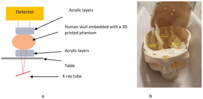
Modern 3D printing technology allows rapid prototyping of vascular phantoms based on an actual human patient with a high degree of precision. Using this technology, we present a platform to accurately simulate clinical views of neuro-endovascular interventions and devices. The neuro-endovascular interventional phantom has a 3D printed cerebrovasculature model derived from a patient CT angiogram and embedded inside a human skull providing bone attenuation. Acrylic layers were placed underneath and on top of the skull, simulating entrance and exit tissue attenuation and also simulating forward scatter.
The 3D model was connected to a pulsatile flow loop for simulating interventions using clinical devices such as catheters and stents. To validate the x-ray attenuation and establish clinical accuracy, the automatic exposure selection by a clinical c-arm system for the phantom was compared with that for a commercial anthropomorphic head phantom (SK-150, Phantom Labs). The percentage difference between automatic exposure selection for the neuro-intervention phantom and the SK-150 phantom was under 10%.
By changing 3D printed models, various patient diseased anatomies can be simulated accurately with the necessary x-ray attenuation. Using this platform various interventional procedures were performed using new imaging technologies such as a high-resolution x-ray fluoroscope and a dose-reduced region-of-interest attenuator and differential temporally filtered display for enhanced interventional imaging. Simulated clinical views from such phantom-based procedures were used to evaluate the potential clinical performance of such new technologies.
Description of Purpose
Endovascular image-guided interventions (EIGI) [1] are modern day minimally invasive treatments for several neurovascular diseases such as strokes, aneurysms etc. The catheters are inserted through the femoral artery and guided into the treatment area. Once the diseased area is located, the treatment devices such as stents, coils and balloons are then deployed. The entire procedure is carried out under x-ray imaging guidance. Figure 1 shows an example aneurysm in the left side Intracranial Carotid Artery segment of a patient. The patient was treated with a Pipeline Embolization Device (PED, Medtronic, Dublin, Ireland), which is a flow diverter stent. Figure 2 shows an image of the deployed PED’s, acquired using the traditional state-of-the-art Flat Panel Detector System with 194 μm pixel size (typically ranging from a 150μm - 300μm for FPD’s). Due to such poor resolution the PED device structure is barely visible. To provide improved imaging during the intervention, a High Resolution Fluoroscope based on Charge Couple Device (HRF-CCD) technology [2] with a pixel size of 35μm was previously developed and used during the treatment procedure of figure 1. Figure 3 shows an image of the deployed PEDs acquired using the HRF-CCD technology. It can be seen that the visualization of the PED in figure 3 is significantly improved compared to figure 2. As the imaging state-of-the-art is constantly evolving with new technologies being introduced, it is important to be able to simulate such interventional procedures for benchtop testing of new imaging technologies to evaluate their clinical performance.
Figure 1.
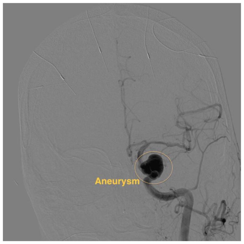
DSA image showing an aneurysm in the patient’s ICA region of the printed model. The image was acquired using the traditional FPD system.
Figure 2.
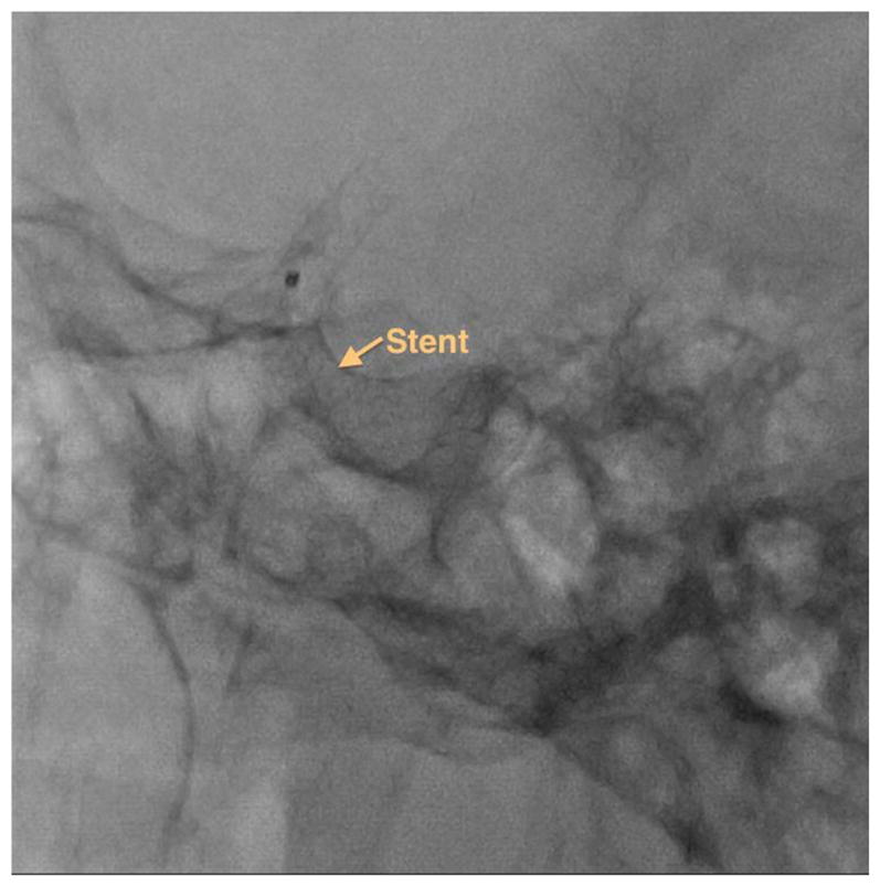
Post deployment image showing PED stents used to treat the aneurysm shown in figure 1. The image is acquired using the traditional FPD system.
Figure 3.
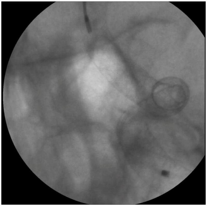
Post deployment image showing PED stents used to treat the aneurysm shown in figure 1. The image is acquired using the high resolution HRF-CCD system.
In this work, we provide a new platform that accurately simulates the patient diseased vasculature using 3D printing technology along with realistic simulation of bone and tissue attenuation. The platform is used to acquire simulated clinical views of interventional procedures using two new imaging technologies: a high resolution fluoroscope detector, and real–time, resolution-enhanced and dose-reduced image guidance techniques.
Methods
Model description and attenuation validation
An x-ray image is formed by the differential attenuation of the x-ray beam within a patient’s body. During an endovascular neurointervention, the significant sources of x-ray attenuation are the human bone (skull) and the soft tissue (including human cerebral cortex). The human cerebrovasculature is simulated by 3D printing models based on a patient CT angiogram. The process of generation of 3D printed models was previously described in [3,4]. The bone attenuation was simulated by placing the model inside a human skull. The tissue attenuation was simulated by placing a stack of one inch acrylic layers underneath the skull (simulating entrance tissue) and above the skull simulating the exit tissue. For this work a total stack of 5 one inch layer blocks were used. The model setup is shown in figure 4.
Figure 4.
a) Schematic diagram of the neurointervention phantom framework. b) Human skull embedded with a 3D printed model
To simulate flow conditions, the model is connected to a flow loop and water was circulated inside the loop using a pulsatile pump. Using this setup, catheter based interventions can be performed on the 3D printed models with diseased anatomy. Vascular models with varying patient diseased pathologies, such as varying aneurysm size and locations can be easily 3D printed. By embedding them in the above phantom, different clinical interventions can be performed.
Phantom Validation
For validation, x-ray attenuation of the composite phantom was compared with the attenuation of a commercially available anthropomorphic phantom (SK 150). Images of the two phantoms at similar fields of view were acquired using the commercial x-ray unit (Toshiba Infinix Biplane C-arm) were acquired under fluoroscopy, digital angiography (DA) and digital subtraction angiography (DSA) conditions. The x-ray exposure parameters such as kV, mA and ms were selected by the C-arm using the automatic exposure control settings. Using these parameters, the air kerma at 60 cm from the x-ray source was calculated. The difference in the air kerma calculated was used to validate the x-ray attenuation equivalence.
Application Examples
Detector image quality comparison study
In order to improve resolution during the intervention treatment a HRF based on complementary metal oxide semiconductor (HRF-CMOS) with a pixel size of 75 3m was previously developed. To determine whether HRF-CMOS can improve imaging of treatment devices in the clinic an intervention using a PED was simulated in the above phantom on a 3D printed phantom simulating an aneurysm in the Middle Cerebal Artery region. After deployment of the PED a DSA run was acquired using the HRF-CMOS and the traditional FPD detector with iodine as the contrast agent. Figure 5 shows a post-deployment image acquired using HRF-CMOS, and figure 6 shows the image with contrast injection. Figure 7 shows a post-deployment image acquired using the FPD, and figure 8 shows the image with contrast injection. Figure 9 shows the edge profile of figure 6 and figure 10 shows the edge profile of figure 8 acquired using a Sobel edge detector mathematical filter.
Figure 5.
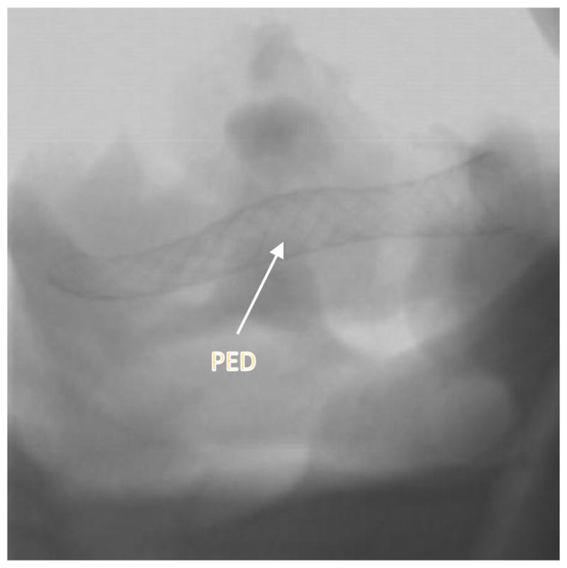
Post deployment image showing PED stent. The image is acquired using the HRF-CMOS system.
Figure 6.
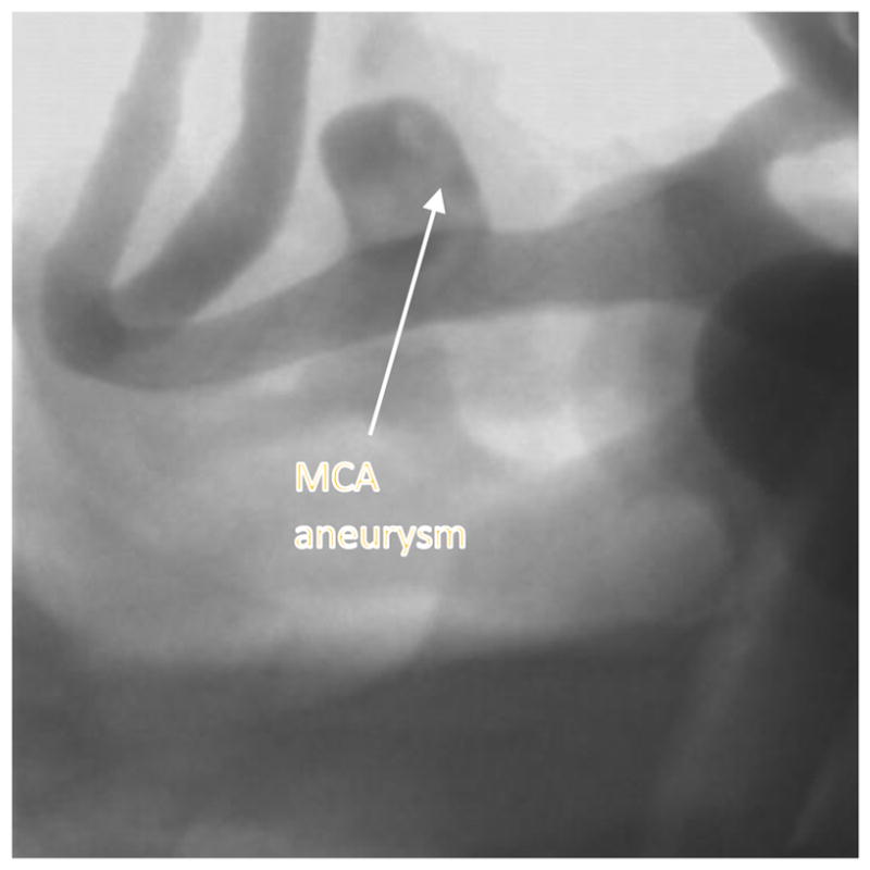
Post deployment image with contrast showing PED stent deployed across the MCA aneurysm . The image is acquired using the HRF-CMOS system.
Figure 7.
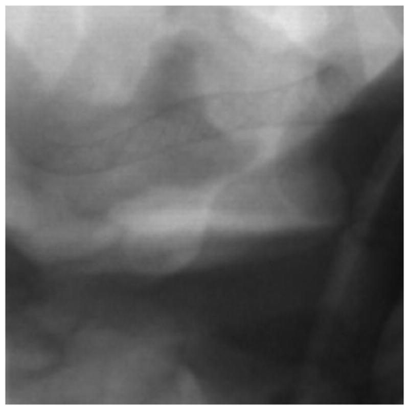
Post deployment image showing PED stent. The image is acquired using the traditional FPD system.
Figure 8.
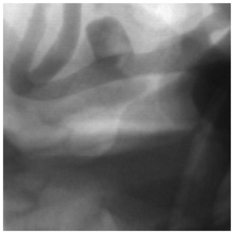
Post deployment image with contrast showing PED stent deployed across the MCA aneurysm. The image is acquired using the traditional FPD system.
Figure 9.
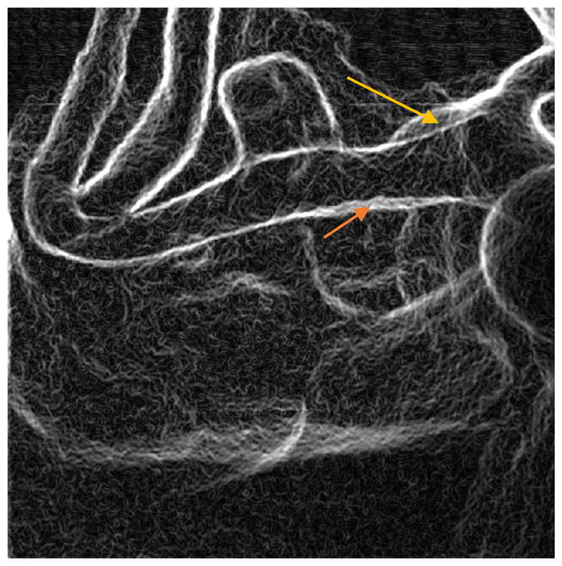
Edge image of figure 6 (HRF-CMOS) derived using Sobel Edge Detector. The arrows indicate the two positions with poor wall apposition as marked by the rater
Figure 10.
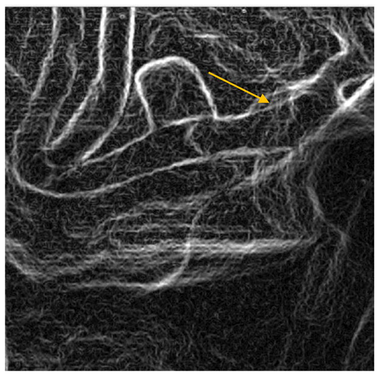
Edge image of figure 8 (FPD) derived using Sobel Edge Detector. The arrow indicates the one position with poor wall apposition as marked by the rater
Real-time resolution-enhanced and dose-reduced ROI attenuator and display for neurointerventional procedures
The critical aspect of the neurointervention is the actual deployment of treatment devices. It is important for the neurointerventionalist to visualize the deployment and, as well, to monitor the interaction of the devices with the proximal and distal vasculature. For example, during PED deployment, it is critical to visualize the aneurysm region and how the device structure changes during it deployment. However, PEDs have a distal wire segment for providing additional support to the actual stent which when not monitored could perforate the distal vasculature due to the forces applied on it during the deployment of the stent. Hence, peripheral monitoring of the procedure is also necessary. An imaging technique enhancing the visualization of treatment devices such as stents and coils at lower integral dose to the patient during a neuro-intervention was developed and simulated using the above phantom.
A 3D printed model simulating the patient’s left-side cerebro-vasculature, consisting of aneurysms in the Internal Carotid Artery (ICA) and the Middle Cerebral Artery (MCA) segment, was embedded in the above phantom. A PED was deployed to treat the ICA aneurysm using real-time x-ray images from a HRF-CMOS detector with a 7.5 x 6.5 cm FOV. A 0.7 mm thick differential copper attenuator with a 10 mm diameter circular opening for the Region of Interest (ROI) was used to reduce the entrance skin dose in the periphery[5]. The ROI was aligned to the PED deployment area. Two displays were provided: one, the entire FOV with brightness-difference corrected and noise reduced by different temporal recursion filtering in the ROI and the dose attenuated periphery region and second, an enhanced image of regular dose in the ROI treatment area, resampled to a pixel size of 35 3m using bilinear interpolation.
Figure 11 shows the ICA aneurysm. In this model there is also an aneurysm in the MCA region. Figure 12 shows the large FOV dose-reduced image and figure 13 shows the corresponding background subtracted roadmap image. Figure 14 shows the ROI interpolated image and figure 15 shows the corresponding background subtracted roadmap image.
Figure 11.
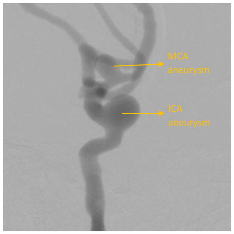
DSA showing an aneurysm in the left ICA and MCA region
Figure 12.
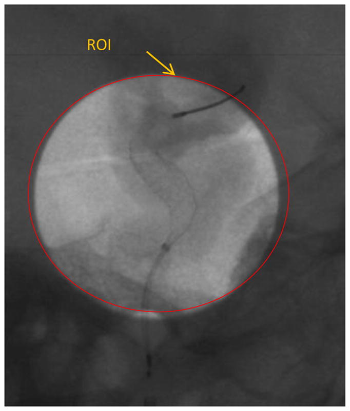
A single image from the sequence obtained during treatment of the ICA aneruysm shown in figure 11, using the new dose-reduced and display-enhanced imaging technique.
Figure 13.
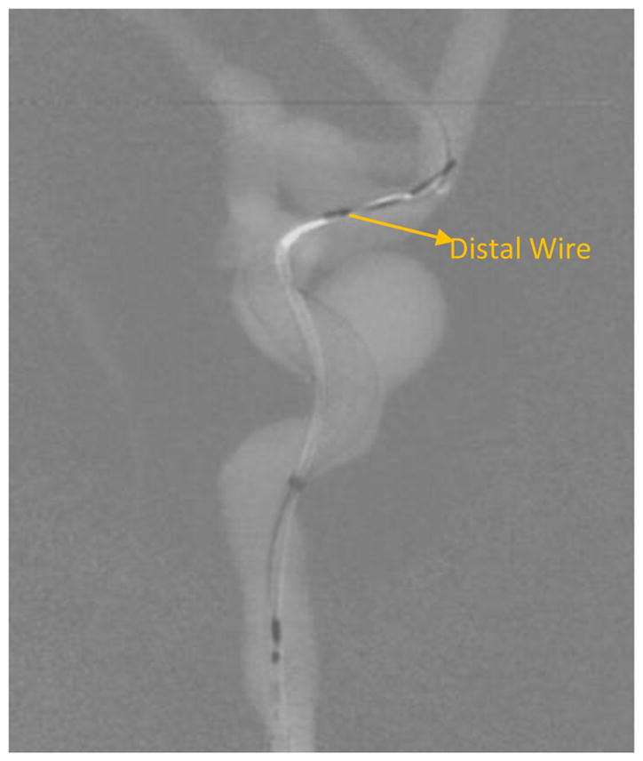
Background subtracted image of figure 12.
Figure 14.
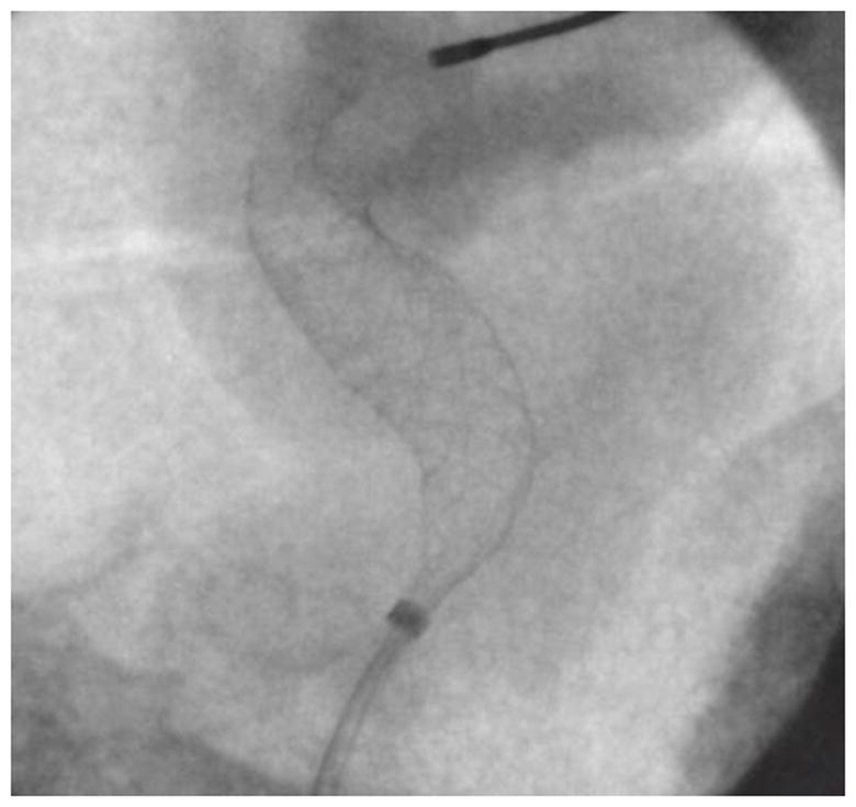
ROI in figure 12 zoomed in using bicubic interpolation.
Figure 15.
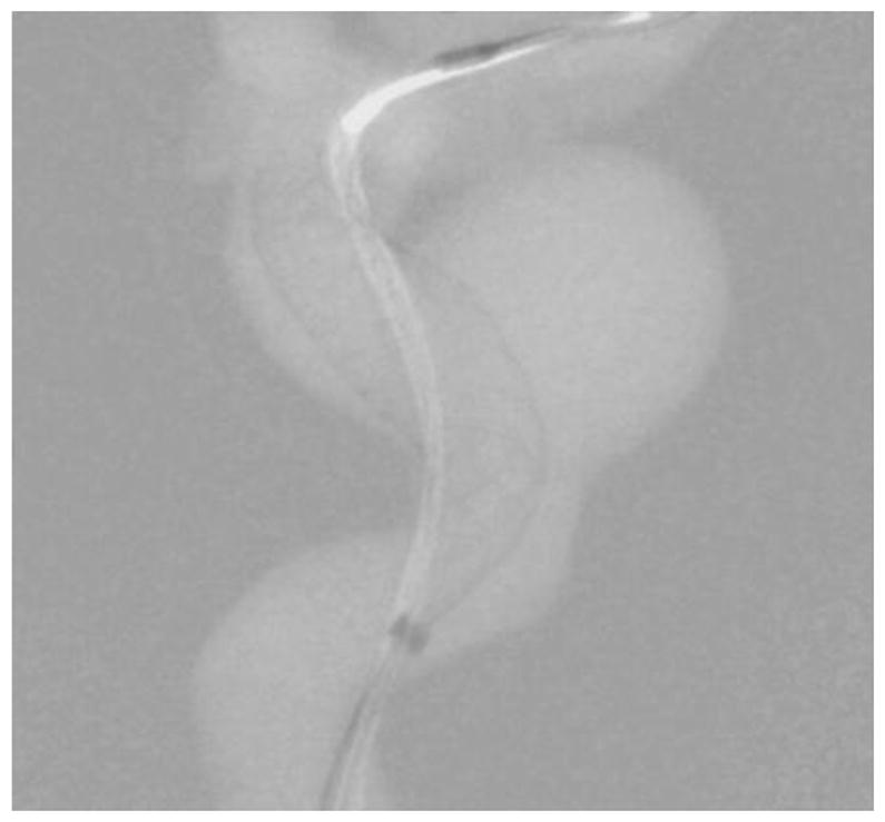
Background subtracted roadmap image of figure 14.
Results
The percentage difference in the air kerma between the proposed phantom and the SK150 phantom was calculated to be less than 10% for fluoroscopy, DA and DSA exposure ranges. This indicates that the x-ray attenuation offered by the neurovascular phantom is comparable to the clinical attenuation.
Clinical neurointerventions such as aneurysm treatment with a PED were successfully simulated in the neurovascular phantom using new image detector technologies such as the HRF-CMOS and new intervention techniques with dose reduction. The images shown in figures 5 to 8 and 11 to 15 show the PEDs with anatomical structures similar to clinical images.
Using the resolution enhanced and dose reduced technique, a 56% reduction in entrance air kerma was achieved and a 512 x 512 pixel area within the ROI was magnified by two times improving the visibility of the PED and yet maintain visibility in the periphery region.
Discussion
As the imaging technology evolves, to evaluate their clinical performance, a platform that accurately simulates clinical interventions is necessary. For testing the performance of an imaging detector during a neurointervention, it is important to simulate both the patient (cranium) x-ray attenuation and the interventional procedure as well. In the neurovascular phantom presented in this work the x-ray attenuation was simulated using a combination of human skull and acrylic layers. By changing the acrylic layers, one can simulate different patients with different thicknesses. The cerebrovasculature was simulated using 3D printed models based on actual patient anatomy. By changing the 3D printed models different patients with various diseases can be simulated.
Traditionally, standard quantitative metrics such as DQE, MTF, etc. have been used to evaluate the generic performance of a detector technology. But they fail to evaluate the performance specific to a particular task. Using the phantom presented in this work, one can setup the study to evaluate the detector performance specific to a particular task.
During a PED deployment it is crucial to visualize the PED, and the changes induced in its geometry due to different stages of the deployment. Post deployment, it is also necessary to check if the PED has good vessel wall apposition. Failure of such, could result in peripheral flow into the aneurysm resulting in failure of the treatment. With the new HRF-CMOS technology it is easier to visualize such information compared to the traditional FPD. In the detector image quality comparison study, the unsubtracted DSA image sequences post PED deployment acquired using both the HRF-CMOS (figures 5 ,6) and the FPD ( figures 7,8) were presented to a blinded neurointerventionalist rater. The raters preferred the visualization of the PED in the HRF-CMOS images compared to FPD images. The edge images shown in figures 9 and 10 were presented to the rater. The rater was asked to mark places with poor wall apposition. Two places were marked on the HRF-CMOS image, whereas only one place was marked on the FPD image. The results from this study indicated that performance of HRF-CMOS in visualizing PED deployment was better compared to FPD.
While visualization of the PED within the aneurysm region is important, it is also important to visualize the periphery. In the image shown in figure 11, the main treatment area is the aneurysm in the ICA region; however, there is also an aneurysm in the MCA region. As seen in figures 12 and 13, the PED has a distal wire segment and while deploying the PED one has to also monitor the movement of this distal wire segment, in this particular case its interaction with the MCA aneurysm. In the real-time resolution-enhanced and dose-reduced attenuator and display technique, the visualization of the PED is enhanced by magnifying the ROI area (using digital interpolation) as shown in figure 14 and 15 and by using the ROI attenuator the entrance air kerma is reduced by 56% without losing the visualization of the periphery regions, especially the distal wire segment shown in figure 13.
Conclusions
The new neurovascular phantom can offer a realistic substitute to an actual clinical procedure and can be used for benchtop testing of new imaging devices and techniques.
References
- 1.Rudin S, Bednarek DR, Hoffmann KR. Endovascular image guided interventions (EIGIs) Med Phys. 2008 Jan;35:301–309. doi: 10.1118/1.2821702. http://www.ncbi.nlm.nih.gov/pubmed/18293585. [DOI] [PMC free article] [PubMed] [Google Scholar]
- 2.Jain A, Bednarek DR, Ionita C, Rudin S. A theoretical and experimental evaluation of the microangiographic fluoroscope: A high-resolution region-of-interest x-ray imager. Med Phys. 2011;38(7):4112–26. doi: 10.1118/1.3599751. https://www.ncbi.nlm.nih.gov/pubmed/21859012. [DOI] [PMC free article] [PubMed] [Google Scholar]
- 3.Russ M, O'Hara R, Setlur Nagesh SV, Mokin M, Jimenez C, Siddiqui A, Bednarek D, Rudin S, Ionita C. Treatment Planning for Image-Guided Neuro-Vascular Interventions Using Patient-Specific 3D Printed Phantoms. Proc SPIE Int Soc Opt Eng. 2015:9417. doi: 10.1117/12.2081997. https://www.ncbi.nlm.nih.gov/pmc/articles/PMC4712717/ [DOI] [PMC free article] [PubMed]
- 4.Ionita CN, Mokin M, Varble N, Bednarek DR, Xiang J, Snyder KV, Siddiqui AH, Levy EI, Meng H, Rudin S. Challenges and limitations of patient-specific vascular phantom fabrication using 3D Polyjet printing. Proc SPIE Int Soc Opt Eng. 2014;9038:90380M. doi: 10.1117/12.2042266. https://www.ncbi.nlm.nih.gov/pubmed/25300886. [DOI] [PMC free article] [PubMed] [Google Scholar]
- 5.Swetadri Vasan S, Ionita C, Bednarek D, Rudin S. A novel Region of Interest (ROI) imaging technique for biplane imaging in interventional suites: high-resolution small field-of-view imaging in the frontal plane and dose-reduced, large field-of-view standard-resolution imaging in the lateral plane. Proceedings of SPIE--the International Society for Optical Engineering; 2014. p. 90332F. http://doi.org/10.1117/12.2043460. [DOI] [PMC free article] [PubMed] [Google Scholar]


