Abstract
The 3D anatomical complexity of the foot and ankle and the importance of weight-bearing in diagnosis have required the combination of conventional radiographs and medical CT.
Conventional plain radiographs (XR) have demonstrated substantial limitations such as perspective, rotational and fan distortion, as well as poor reproducibility of radiographic installations. Conventional CT produces high levels of radiation exposure and does not offer weight-bearing capabilities.
The literature investigating biometrics based on 2D XR has inherent limitations due to the technology itself and thereby can focus only on whether measurements are reproducible, when the real question is whether the radiographs are.
Low dose weight-bearing cone beam CT (WBCT) combines 3D and weight-bearing as well as ‘built in’ reliability validated through industry-standardized processes during production and clinical use (quality assurance testing).
Research is accumulating to validate measurements based on traditional 2D techniques, and new 3D biometrics are being described and tested.
Time- and cost-efficient use in medical imaging will require the use of automatic measurements. Merging WBCT and clinical data will offer new perspectives in terms of research with the help of modern data analysis techniques.
Cite this article: EFORT Open Rev 2018;3 DOI: 10.1302/2058-5241.3.170066
Keywords: weight-bearing CT, cone beam, 3D biometrics
Introduction
Why do we need weight-bearing cone beam CT?
The foot and ankle is a highly complex anatomical and biomechanical structure combining 28 bones in a maze of 3D architectural arrangements defined by angles, lines, slopes and others. This whole complex is subject to acute and chronic structural changes with the repeated compression stresses of gravity and ground reaction force during a lifetime of walking and/or running, standing and other human activities. The appropriate understanding of how these structures interact and react under stress is essential to our understanding of pathology. As it stands, we still deem this understanding to be very crude. One reason for this is the limited 2D imaging capabilities provided by conventional radiography, which results in a superimposition of lines and shades mixing bone, joints and soft tissue, making it difficult to ascertain the relative spatial positions of each component. Furthermore, 2D radiographs (XR) have inherent limitations due to the spatial geometry of x-ray beams responsible for rotation distortion and fan effect (Fig. 1), so that the angles and the distances measured in the picture do not correspond to angles and the distances in the real object.1,2 Since the 1980s, however, with increased accessibility to CT, this limitation has been partially overcome by combining the weight-bearing information provided by standing XR with the 3D information provided by CT. However, this situation remains imperfect. The main reported limitations are as follows: high radiation dose3 and absence of weight- bearing pertaining to CT; poor reproducibility and poor reliability of measurements with XR;4,5 time necessary for and cost of comparative, bilateral dorsal plantar, lateral and anteroposterior (AP) XR and CT sets.5 There is therefore a need for a solution which can enable low-dose, fast, reliable, standing, 3D assessment of the foot and ankle. A number of attempts have been made at simulated weight-bearing in CT, mostly for research purposes, which have allowed insights into the effects of weight-bearing on the architecture of the human foot, in both healthy and pathological conditions. In both cases, 2D biometrics such as the height of the medial arch, forefoot supination and hindfoot valgus change significantly under load, and pathological conditions are systematically underestimated in absence of load.6-8 However, these methods using CT are still limited by significant downfalls beginning with high radiation dose, and practical issues such as those summarized by Barg et al9 in a recent review article, namely: partial weight-bearing potentially underestimating its impact and passive external loads underestimating the actions of active muscle forces when actually standing. It could also be stated that the apparatus used in the studies is mostly custom-made and cumbersome to use in daily practice.
Fig. 1.
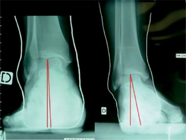
Perspective malalignment on Meary type hindfoot alignment views (pictures courtesy of Pr Jean Brilhault, MD,PhD, Tours University Hospital, France).
Reproducibility of measurements and validity of the image: impact on patient management
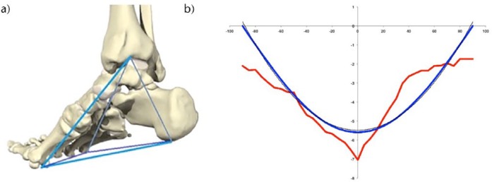
There is a systematic and inevitable limitation when investigating anatomical measurements with 2D XR, which pertains to the difference between assessing reproducibility of the measurement and reliability of the material on which the measurement is performed. The literature concentrates on measuring whether two or more observers (interobserver reliability) are able to produce the same value using the same picture, and whether one observer is able to produce the same value using the same picture at two different times (intraobserver reliability).4,10-13 In other words, when investigating a radiographic measurement, this amounts to investigating whether instructions are good enough to ensure repeatability and whether observers can obey instructions. There is a risk that two observers will understand the same instruction in different ways, although this might be suppressed in the future by the use of artificial intelligence in imaging, where the observers are replacable by an AI algorithm. However, when this measurement is repeated on a document which does not give an accurate picture of reality, and even when it is an excellent measurement in terms of reproducibility, it can only reproduce an error. In fact, the real question is not whether the measurement is good enough, but whether the imaging technique can reliably reproduce the dimensions of the object it is picturing. In order to assess this, it would be necessary to repeat the investigation on a single patient. This is very difficult to accomplish for two reasons. First, it is complicated to ethically justify exposing patients to unnecessary radiation. Second, the mathematical demonstration that 3D angles and distances in an object will project differently on a plane depending on the rotation of the object relative to the source is self-evident and it renders such an exploration superfluous (Fig. 2). However, such an investigation would be valid and acceptable using a cadaver specimen. Such an experiment was carried out by Baverel et al,1 which demonstrated that a 30° rotation could produce a 30% change in the value of the projected hindfoot Meary angle. We must insist here on the impact this has for patients. In another study,14 comparing a conventional radiographic hindfoot angle to a 3D angle, it was found that the correlation between the 3D angle and the projected one was only 72%. This means that when 1000 patients are assessed, 280 measurements are not valid. In the same study, two patients who had neutral alignment in reality were evaluated according to 2D XR as a 5° varus in one case and a 15° valgus in the other, a situation in which the therapeutic decisions in two patients with the same neutral alignment may be completely opposed. This is not something that can be assessed using numerical statistical numbers such as correlation coefficients, but rather requires the use of graphical techniques such as Bland and Altman’s,15 which shows that, where global correlation coefficient values of the measurement technique may be ‘acceptable’, individual variations due to unreliability of the radiographic technique may be unacceptable. This could be partially compensated by clinical training, but it cannot be ignored and it is certainly an area where weight-bearing cone beam CT (WBCT) offers dramatic improvement.
Fig. 2.
(a) The Kapandji triangular-based Pyramid model of the foot and ankle;14 (b) modelized (left) and experimental (right) variation of hindfoot alignment in relation with rotation of the foot-ankle complex.1
New challenges
This world of possibilities does not come without new challenges. The development of a new 3D environment does not necessarily make things easier in the clinical setting, where surgeons have been trained to interpret information based on pixels and shades of gray, not voxels, coordinates and Hounsfield units. Furthermore, the reality of the dynamic function of the foot and ankle and the forces that it creates is very different from the forces in the static foot. The foot is actually a dynamic and moving structure, so measuring something more accurately on a static foot under these circumstances does not mean it will make any difference in terms of patient outcome; therefore, prospective, comparative studies of clinical and cost efficiency will have to be carried out. Finally, the accumulation of infinitely more abundant information from the 3D environment increases the time needed for interpretation and potentially invalidates previously described 2D measurements, which need to be adapted to the new setting. This is the endeavour of the Weight-Bearing CT International Study Group16 (WBCT ISG), which was constituted in September 2017 during the International Federation of Foot and Ankle Society (IFFAS) congress on the initiative of a panel of independent international experts and users of the new technology, including representatives from the realm of radiology and from the major international orthopaedic foot and ankle scientific organizations. The group aims to investigate the possibilities, validate new measurement systems and organize and focus the international research effort in order to produce common guidelines for the clinical use of WBCT.
Cone beam CT: technical background
Cone beam technology was first described in 1998 by Mozzo et al,17 and immediately found applications in the dental arena. Initial limitations included poor spatial definition, high costs and large footprint, all rapidly overcome by technological advances. Nowadays, the technology has largely supplanted XR and has enabled new technologies to be born and developed, some of which directly benefit dental patients, such as custom surgical guides and implants. In orthopaedics, the use of cone beam CT (CBCT) was first published in 2011 by Zbijewski et al,18 and the first mention of weight-bearing was in a 2013 paper by Tuominen et al.19
Scientific basis of WBCT technology
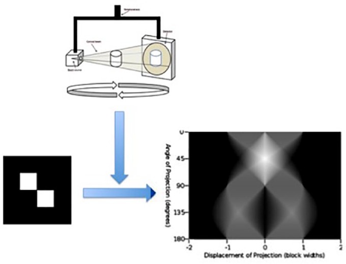
A cone beam is a rotating XR, where the centre of rotation is the investigated object, the photon source is at one end of the diameter axis, and the target (a digital silicon detector panel) at the other. The target is continuously projected with the photons which have traversed the object, and the result is an intermingled array of lines and shades called a sinogram (Fig. 3), which has to be interpreted using mathematical transforms (the Fournier, which reconstructs multiple simple sinus functions from a single complex one, and the Radon, which reconstructs a set of 3D coordinates). The result is a 3D cylindrical volume or field of view (FOV), which varies in diameter between 10 cm and 40 cm (Fig. 4). This is divided into smaller cubes or voxels: the 3D equivalent of 2D pixels. The side of each voxel is usually around 0.3 mm (slab thickness). The resolution depends essentially on the density of receptors on the target panel but also on software and memory capabilities. A typical FOV contains several hundred million voxels. Each voxel has four dimensions including a set of three coordinates (x, y, z) and a value for the radiodensity, given as the Hounsfield Unit (HU). For example, the radiodensity of air is -1000 HU. Acquisition time is typically under a minute. In terms of radiation exposure,3,9 a CBCT scan with a small, single foot FOV is around 2 Micro Sieverts (mSV), a large FOV bilateral foot scan around 6 mSV. As a comparison, United States daily background exposure is around 8 mSV, 1 mSV for an extremity conventional XR, 2 mSV for a chest XR and 25 mSV to 100 mSV (or typically 70 m SV for an ankle scan) for an extremity CT. In terms of size, a typical machine will weigh around 250 kg and fit in a 1 m × 1 m footprint (Fig. 5).
Fig. 3.
Technical principles of cone beam technology.
Fig. 4.
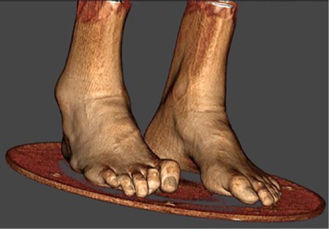
Example of a 3D rendering skin view of a bilateral standing cone beam CT in a case of severe cavovarus deformity.
Fig. 5.
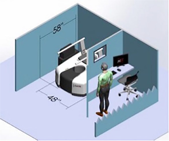
Footprint of a typical WBCT (image courtesy of Curvebeam, LLC, Warrington, PA, USA).
As we have seen, one of the major improvements with WBCT is the built-in reliability, ensuring that the output volume corresponds in terms of dimensions and density to the real investigated object. This reliability is checked on a regular basis through quality assurance testing (QA). The QA procedures are designed to check for image quality, accuracy of distance measurements, consistency and radiation output. They consist of scanning specific QA phantoms provided by the manufacturer. Image data is then captured and compared with the known values.
Current clinical use and impact of WBCT in the foot and ankle
Cost
The cost of a typical WBCT machine is between €150 000 and €300 000. Overall costs also include technical personnel and running costs. As expected, depending on local reimbursement conditions, the financial schemes to ensure sustainability will vary.
Learning curve
The amount of data provided by WBCT is far greater than with weight-bearing 2D XR or non-weight-bearing conventional CT, so we are in fact at the beginning of the learning curve in the clinical setting. In an unpublished document presented at the Open WBCT ISG16 meeting at the 2017 IFFAS congress, one of the authors commented on the time required for a human observer to perform a large number of flat foot measurements (necessary to an ongoing research) equivalent to known 2D XR methods using WBCT datasets. This time was 20 minutes per WBCT scan, compared with the 5 minutes necessary to perform similar measurements on 2D XR. Despite this being in the research (as opposed to clinical) setting, it highlights the fact that the challenge mainly stems from having to find the correct plane in which to perform the measurement. Having the whole volume available rather than the stacked-up, distorted, 2D equivalent makes it necessary to choose from an infinite number of 2D slices. This stems from the fact that most of the available and validated measurements were described in 2D, on XR. To overcome this issue, some WBCT machines come with built-in software solutions, which produce reconstructed radiographs from the 3D data, or digitally reconstructed radiographs (DRRs)20 (Fig. 6). However, this technique has three drawbacks: the quality is lower than with conventional radiographs; their use has not been properly validated in the clinical setting; and mostly, they are certainly a method for suppressing the 3D data and going back to 2D. However, they may be sufficient for 2D measurements and are probably necessary as a transition tool. To illustrate this point, it is paramount to state that our surgeon brains were trained and wired to make diagnosis, planning and therapeutic decisions based on plain 2D radiographic films on lightboxes, and hand-drawn angles. These 2D tools are not necessarily valid in the new 3D environment. The use of the WBCT technology requires switching to 3D computer screens or tablets and computerized measurements, which is the travel equivalent of switching from paper maps to satellite navigation. This is a long and winding path, which takes place at an individual level but also on an academic one and concerns the whole profession. Part of the solution to making the technology more accessible will come from the development of automatic measurement systems, which will contribute to speeding up the workflow.21 However, this will not necessarily render the decision-making process easier, with many more parameters to take into account, which were previously invisible with the XR + CT setup. It will be important to pursue the research effort in order to digest this data and make it usable in daily practice.
Fig. 6.
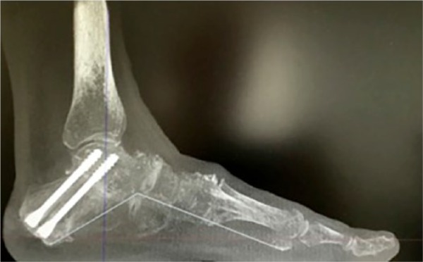
Example of a digitally reconstructed radiograph with computed measurement of medial foot arch following subtalar arthrodesis.
Potential radiation and time-saving
In an unpublished study on the local use of the technology in his own institution, one of the pioneering authors on WBCT provided, during the open session of the WBCT ISG in the 2017 IFFAS congress,16 the following numbers: since 2012, more than 8000 scans have been performed, most of them bilateral. The use of conventional XR has dropped by 83% (now only used for early postoperative, non-weight-bearing) and the use of CT by 96% (now only used for acute injury with severe soft-tissue damage). The same author also published data relative to savings in radiology technician allocated time, which was estimated to have dropped by 15 800 hours per year from 22 550 in the XR + CT setup to 6750 with the WBCT setup.16 The total radiation exposure was estimated in the same study to have dropped by a dose equivalent to that of 6000 XR or 6000 mSV, which is comparable with 750 years of United States equivalent background dose. Of course, this utilization was specific to a specialized and pioneering institution with a strong focus on research. However, the trend followed here is the same as was seen 15 years ago in the dental arena,22 so it is worth following up to investigate whether the possible benefits of this technology for our patients are confirmed in the future.
Indications
The literature on WBCT remained virtually nonexistent until 2008 but has been steadily growing since. The main subjects of interest have been: flat foot, the subtalar joint, the distal tibiofibular joint, varus tibiotalar osteoarthritis, first ray hypermobility, hallux rigidus (HR) and hallux valgus (HV). These recent and pioneering papers focused on identifying or confirming anatomical modifications associated with pathological conditions in the foot and ankle, which were unknown or unseen before. Initial findings are described below.
Concerning flat feet and the subtalar joint, flat foot measurements analogous to conventional radiologic parameters may be obtained using WBCT with better detection of severity;23 patients with flat foot deformity have more innate valgus in their talar shape and in their subtalar alignment;24-26 in an uninjured population, the fifth metatarsal demonstrates plantarflexion relative to the first metatarsal in patients with flat feet relative to controls;27 subtalar joint orientation may be a risk factor for the development of ankle joint osteoarthritis.28
With regard to the first ray, HR patients have metatarsus primus elevatus, increasing with the severity;29 mobility is increased in the tarso-metatarsal joint but also in all the other joints of the first ray in patients with HV.30
Concerning the tibiofibular mortise, there is internal rotation of the talus in the varus osteoarthritic ankle, increasing with severity; weight-bearing rotation of the talus within the normal mortise is around 10°, fibular posterior translation is 1.5 mm and external rotation 3°, and comparison with the contralateral side seems to be more reliable than with the population norm.31,32
In our experience, indications have mostly been in fields where the combination of 3D and weight-bearing seemed appealing. However, we suggest that in the future, the whole range of foot and ankle conditions should be considered in a more straightforward way through the new technology. In HV, for example, the role of coronal rotational position of the first metatarsal and sesamoïds has already been proven as fundamental to be taken into account for correction.33-36 It seems logical to anticipate that in the future the understanding, diagnosis and treatment of forefoot conditions will also benefit from WBCT. One can again assume that automatic measurements will accelerate this phenomenon.
Recent advances and perspectives
How to measure in 3D
Most of our measurement tools in the radiographic foot and ankle realm are single or 2D measurements. Their goal is to define the normal position of one structure which is variable in its position (a point or a line on a bone, for example the anatomical axis of the first metatarsal), by giving a measure (an angle or distance) of its current position relative to another structure which is supposed not to be variable (a point or line on another bone, for example the second metatarsal, or on the ground plane). These tools are easy to manipulate because they are easy to draw by hand on a radiographic film or to click on a computer screen. In a 3D environment, however, they become more difficult to use because they are 2D. A plane must be chosen in order to apply them, but an infinity of planes are possible. There are two possible ways to overcome this today and both are used in daily practice. The first way is to use DRRs.2 DRRs are a slice within the 3D volume, which is thickened in order to stack up the information contained within the adjacent volume. In our view, this tool serves only as a transition towards better use of the 3D data. The second way is to perform traditional 2D measurements on a chosen slice, but we have seen that this is time-consuming and perhaps not compatible with a typical foot and ankle outpatient workflow. Despite this, an investigation was performed in 2014 by Richter et al5 comparing measurements performed on 2D XR, CT and WBCT. Their conclusion was that only WBCT was able to provide the true measurements due to its independence from rotational and projection bias.
Hindfoot alignment (HA) in 3D, or the concept of 3D biometrics
The concept of 3D biometrics rests on two paramount features: mechanical relevance and four points to describe a volume.
Mechanical relevance
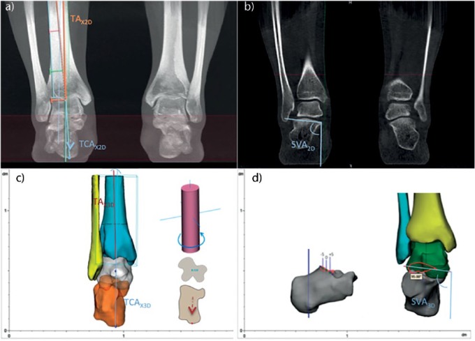
HA needs to be known because we need to picture what forces drive the hindfoot and the ankle into deformity. This has well-known clinical and pathological implications such as prosthesis failure37-39 or ankle instability40 amongst others. One way to picture these forces is by measuring the offset between where body weight is applied (the ankle joint) and where ground reaction force is (the sole of the foot). This is an indirect measure of the torque which results from the offset, from which the driving force of the deformity originates. This notion was introduced by Saltzman’s and El Khouri’s ‘Hindfoot Alignment View’,41 which has since then become the benchmark for HA. The founding paper in 1995 reported a mean 3.6 mm valgus offset with an interobserver correlation coefficient of 0.97 and 95% asymptomatic patients within 15 mm of the lowest calcaneal point. In this paper, the direction of body weight was approximated through the anatomical median axis of the tibia, and ground reaction force through the lowest point of the calcaneus. The issue of the approximation inherent to the 2D XR technique was investigated by Burssens et al42 in a 2016 study stating that there is a good correlation between 2D HA and 3D HA, but that 3D HA overcomes the shortcomings encountered by 2D analysis. This paper was the first description of validated HA measurements using WBCT. Computer-aided design operations allowed translation of these 2D measurements towards a 3D environment (Fig. 7).
Fig. 7.
Hindfoot measurements based on 3D reconstruction software (Mimics, by Materialize).
Four points to describe a volume
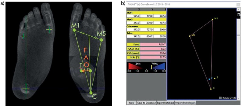
Rather than using three points to describe an angle in a single distorted 2D plane (therefore omitting part of the valuable 3D information), WBCT enables us to use four points in an undistorted volume. Also, since the direction of the vertical is known in the three planes, it can reliably be used to describe the direction of the forces at stake: gravity and ground reaction force. Another key point is to not use the tibia as a reference, because its anatomical axis is only an approximation of the direction of the body weight force vector. Instead, the forefoot may be used as a reference to describe HA. This was first described by Lintz et al14 in a 2012 paper on the ‘ground reaction force calcaneal offset’, and by Arunakul et al43 in a 2013 paper on the ‘tripod index’ – two innovative HA measurements based on the position of the forefoot. In a recent paper, Lintz et al21 described the foot ankle offset (FAO)21 (Fig. 8), a software-based HA measurement where a semi-automatic algorithm, built in with a WBCT machine, uses three points on the sole of the foot and one point in the centre of the ankle joint to measure the offset. These points are manually selected by the investigator. Also, the offset is given as a percentage of foot length to describe the value independently of foot size. This resulted in overall 0.99 and 0.97 inter- and intraobserver reliability coefficients. The value in the normal population was 2.34% with a 95% confidence interval of 1.5% to 3.1%. In a more recent study, Richter et al44 demonstrated the existence of a correlation between the FAO and the real centre of pressure by using custom pressure sensors built into a WBCT machine. This is extremely significant since previous findings by the same author45 looking at individual bone positions within the WBCT assessment had not correlated with plantar pressure measurements using the same apparatus. So even though the individual positions of bones in the foot and ankle may not be predictive of local pressure, the whole 3D structure of the foot seems to be responsible for maintaining the centre of pressure in line with the geometric centre.
Fig. 8.
(a) The foot ankle offset (FAO), or 3D biometric measurement of hindfoot alignment based on WBCT data;21 (b) example of FAO presented on a case using TALAS semi-automatic software (Curvebeam, LLC, Warrington PA, USA).
Future perspectives
Coming from a world in which we had diagnosed and planned from 2D distorted projections, we are now in a 3D undistorted world and we must learn how to diagnose and plan in the new environment. We also know that the next step in terms of imaging will probably be in four dimensions, and multi-tissue, where the dynamic life of the foot will also be within our grasp. Of course we are not there yet, and it is paramount to state here that the improvement of 3D over 2D, however huge it seems today, is only a fraction of what the leap from 3D bone to 4D multi-tissue will represent. The major challenge in the future will be the screening and interpretation of the enormous amount of information provided. A single bilateral weight-bearing scan is relatively time-consuming to interpret in daily clinical use. Developments will have to include validation of automatic measurement tools and modern big data analysis. However, this evolution, which is already seen in other areas of modern life, does not occur without consequences for our role as specialist clinicians and surgeons. For how much of the diagnosis and prognosis, and further, of the therapeutic decision-making process, are we willing to trust artificial intelligence? This question goes beyond the scope of this review, but seems a good starting point to harness correctly the creative process which will lead to these new tools, so that their future use may provide maximum efficiency for our patients while remaining within the reasonable boundaries of what we as doctors consider ethically acceptable.
Footnotes
ICMJE Conflict of interest statement: F. Lintz declares consultancy for Curvebeam LLC, activity relating to the submitted work. C. de Cesar Netto declares consulting fees or honoraria for Curvebeam LLC, activity relating to the submitted work; consultancy for Ossio; stocks/stock options and travel/accommodation/meeting expenses from Curvebeam LLC, activities outside the submitted work. A. Burssens declares a clinical research grant from the University Hospital of Ghent, activity relating to the submitted work; consultancy, payment for lectures, and travel/meeting/accommodation expenses from Curvebeam LLC, activities outside the submitted work. Alexeij Barg declares consultancy for Medartis, activity outside the submitted work. Martinus Richter declares consultancy for Curvebeam LLC, activity relating to the submitted work.
Funding statement
The author or one or more of the authors have received or will receive benefits for personal or professional use from a commercial party related directly or indirectly to the subject of this article. In addition, benefits have been or will be directed to a research fund, foundation, educational institution, or other non-profit organization with which one or more of the authors are associated.
References
- 1. Baverel L, Brilhault J, Odri G, Boissard M, Lintz F. Influence of lower limb rotation on hindfoot alignment using a conventional two-dimensional radiographic technique. Foot Ankle Surg 2017;23:44-49. [DOI] [PubMed] [Google Scholar]
- 2. Barg A, Amendola RL, Henninger HB, et al. Influence of ankle position and radiographic projection angle on measurement of supramalleolar alignment on the anteroposterior and hindfoot alignment views. Foot Ankle Int 2015;36:1352-1361. [DOI] [PubMed] [Google Scholar]
- 3. Mettler FA, Jr, Huda W, Yoshizumi TT, Mahesh M. Effective doses in radiology and diagnostic nuclear medicine: a catalog. Radiology 2008;248:254-263. [DOI] [PubMed] [Google Scholar]
- 4. Sensiba PR, Coffey MJ, Williams NE, II, Mariscalco M, Laughlin RT. Inter- and intraobserver reliability in the radiographic evaluation of adult flatfoot deformity. Foot Ankle Int 2010;31:141-145. [DOI] [PubMed] [Google Scholar]
- 5. Richter M, Seidl B, Zech S, Hahn S. PedCAT for 3D-imaging in standing position allows for more accurate bone position (angle) measurement than radiographs or CT. Foot Ankle Surg 2014;20:201-207. [DOI] [PubMed] [Google Scholar]
- 6. Kido M, Ikoma K, Imai K, et al. Load response of the medial longitudinal arch in patients with flatfoot deformity: in vivo 3D study. Clin Biomech (Bristol, Avon) 2013;28:568-573. [DOI] [PMC free article] [PubMed] [Google Scholar]
- 7. Kido M, Ikoma K, Imai K, et al. Load response of the tarsal bones in patients with flatfoot deformity: in vivo 3D study. Foot Ankle Int 2011;32:1017-1022. [DOI] [PubMed] [Google Scholar]
- 8. Hirschmann A, Pfirrmann CW, Klammer G, Espinosa N, Buck FM. Upright cone CT of the hindfoot: comparison of the non-weight-bearing with the upright weight-bearing position. Eur Radiol 2014;24:553-558. [DOI] [PubMed] [Google Scholar]
- 9. Barg A, Bailey T, Richter M, et al. Weight bearing computed tomography of the foot and ankle. Foot Ankle Int 2017;39:376-386. [DOI] [PubMed] [Google Scholar]
- 10. Tuijthof GJ, Herder JL, Scholten PE, van Dijk CN, Pistecky PV. Measuring alignment of the hindfoot. J Biomech Eng 2004;126:357-362. [DOI] [PubMed] [Google Scholar]
- 11. Reilingh ML, Beimers L, Tuijthof GJ, et al. Measuring hindfoot alignment radiographically: the long axial view is more reliable than the hindfoot alignment view. Skeletal Radiol 2010;39:1103-1108. [DOI] [PMC free article] [PubMed] [Google Scholar]
- 12. Haight HJ, Dahm DL, Smith J, Krause DA. Measuring standing hindfoot alignment: reliability of goniometric and visual measurements. Arch Phys Med Rehabil 2005;86:571-575. [DOI] [PubMed] [Google Scholar]
- 13. Graham ME, Chikka A, Jones PC. Validation of the talar-second metatarsal angle as a standard measurement for radiographic evaluation. J Am Podiatr Med Assoc 2011;101:475-483. [DOI] [PubMed] [Google Scholar]
- 14. Lintz F, Barton T, Millet M, et al. Ground Reaction Force Calcaneal Offset: A new measurement of hindfoot alignment. Foot Ankle Surg 2012;18:9-14. [DOI] [PubMed] [Google Scholar]
- 15. Bland JM, Altman DG. Statistical methods for assessing agreement between two methods of clinical measurement. Lancet 1986;1:307-310. [PubMed] [Google Scholar]
- 16. No authors listed. WBCT-ISG. www.wbctstudygroup.com (date last accessed 09 March 2018).
- 17. Mozzo P, Procacci C, Tacconi A, Martini PT, Andreis IA. A new volumetric CT machine for dental imaging based on the cone-beam technique: preliminary results. Eur Radiol 1998;8:1558-1564. [DOI] [PubMed] [Google Scholar]
- 18. Zbijewski W, De Jean P, Prakash P, et al. A dedicated cone-beam CT system for musculoskeletal extremities imaging: design, optimization, and initial performance characterization. Med Phys 2011;38:4700-4713. [DOI] [PMC free article] [PubMed] [Google Scholar]
- 19. Tuominen EK, Kankare J, Koskinen SK, Mattila KT. Weight-bearing CT imaging of the lower extremity. AJR Am J Roentgenol 2013;200:146-148. [DOI] [PubMed] [Google Scholar]
- 20. Moore CS, Wood TJ, Saunderson JR, Beavis AW. A method to incorporate the effect of beam quality on image noise in a digitally reconstructed radiograph (DRR) based computer simulation for optimisation of digital radiography. Phys Med Biol 2017;62:7379-7393. [DOI] [PubMed] [Google Scholar]
- 21. Lintz F, Welck M, Bernasconi A, et al. 3D biometrics for hindfoot alignment using weightbearing CT. Foot Ankle Int. 2017;38(6):684-689. [DOI] [PubMed] [Google Scholar]
- 22. MacDonald D. Cone-beam computed tomography and the dentist. J Investig Clin Dent 2017;8:e12178. [DOI] [PubMed] [Google Scholar]
- 23. de Cesar Netto C, Schon LC, Thawait GK, et al. Flexible adult acquired flatfoot deformity: comparison between weight-bearing and non-weight-bearing measurements using cone-beam computed tomography. J Bone Joint Surg [Am] 2017;99:e98. [DOI] [PubMed] [Google Scholar]
- 24. Krähenbühl N, Horn-Lang T, Hintermann B, Knupp M. The subtalar joint: A complex mechanism. EFORT Open Rev 2017;2:309-316. [DOI] [PMC free article] [PubMed] [Google Scholar]
- 25. Krähenbühl N, Tschuck M, Bolliger L, Hintermann B, Knupp M. Orientation of the subtalar joint: measurement and reliability using weightbearing CT scans. Foot Ankle Int 2016;37:109-114. [DOI] [PubMed] [Google Scholar]
- 26. Cody EA, Williamson ER, Burket JC, Deland JT, Ellis SJ. Correlation of talar anatomy and subtalar joint alignment on weightbearing computed tomography with radiographic flatfoot parameters. Foot Ankle Int 2016;37:874-881. [DOI] [PubMed] [Google Scholar]
- 27. Yoshioka N, Ikoma K, Kido M, et al. Weight-bearing three-dimensional computed tomography analysis of the forefoot in patients with flatfoot deformity. J Orthop Sci 2016;21:154-158. [DOI] [PubMed] [Google Scholar]
- 28. Colin F, Horn Lang T, Zwicky L, Hintermann B, Knupp M. Subtalar joint configuration on weightbearing CT scan. Foot Ankle Int 2014;35:1057-1062. [DOI] [PubMed] [Google Scholar]
- 29. Cheung ZB, Myerson MS, Tracey J, Vulcano E. Weightbearing CT scan assessment of foot alignment in patients with hallux rigidus. Foot Ankle Int 2018;39:67-74. [DOI] [PubMed] [Google Scholar]
- 30. Kimura T, Kubota M, Taguchi T, et al. Evaluation of first-ray mobility in patients with hallux valgus using weight-bearing CT and a 3-D analysis system: a comparison with normal feet. J Bone Joint Surg [Am] 2017;99:247-255. [DOI] [PubMed] [Google Scholar]
- 31. Lepojärvi S, Niinimäki J, Pakarinen H, Koskela L, Leskelä HV. Rotational dynamics of the talus in a normal tibiotalar joint as shown by weight-bearing computed tomography. J Bone Joint Surg [Am] 2016;98:568-575. [DOI] [PubMed] [Google Scholar]
- 32. Lepojärvi S, Niinimäki J, Pakarinen H, Leskelä HV. Rotational dynamics of the normal distal tibiofibular joint with weight-bearing computed tomography. Foot Ankle Int 2016;37:627-635. [DOI] [PubMed] [Google Scholar]
- 33. Geng X, Zhang C, Ma X, et al. Lateral sesamoid position relative to the second metatarsal in feet with and without hallux valgus: a prospective study. J Foot Ankle Surg 2016;55:136-139. [DOI] [PubMed] [Google Scholar]
- 34. Chen JY, Rikhraj K, Gatot C, Lee JY, Singh Rikhraj I. Tibial sesamoid position influence on functional outcome and satisfaction after hallux valgus surgery. Foot Ankle Int 2016;37:1178-1182. [DOI] [PubMed] [Google Scholar]
- 35. Lamo-Espinosa JM, Flórez B, Villas C, et al. The relationship between the sesamoid complex and the first metatarsal after hallux valgus surgery without lateral soft-tissue release: a prospective study. J Foot Ankle Surg 2015;54:1111-1115. [DOI] [PubMed] [Google Scholar]
- 36. Woo K, Yu IS, Kim JH, Sung KS. Effect of lateral soft tissue release on sesamoid position in hallux valgus surgery. Foot Ankle Int 2015;36:1463-1468. [DOI] [PubMed] [Google Scholar]
- 37. Braito M, Dammerer D, Reinthaler A, et al. Effect of coronal and sagittal alignment on outcome after mobile-bearing total ankle replacement. Foot Ankle Int 2015;36:1029-1037. [DOI] [PubMed] [Google Scholar]
- 38. Frigg A, Nigg B, Hinz L, Valderrabano V, Russell I. Clinical relevance of hindfoot alignment view in total ankle replacement. Foot Ankle Int 2010;31:871-879. [DOI] [PubMed] [Google Scholar]
- 39. Hobson SA, Karantana A, Dhar S. Total ankle replacement in patients with significant pre-operative deformity of the hindfoot. J Bone Joint Surg [Br] 2009;91-B:481-486. [DOI] [PubMed] [Google Scholar]
- 40. Van Bergeyk AB, Younger A, Carson B. CT analysis of hindfoot alignment in chronic lateral ankle instability. Foot Ankle Int 2002;23:37-42. [DOI] [PubMed] [Google Scholar]
- 41. Saltzman CL, el-Khoury GY. The hindfoot alignment view. Foot Ankle Int 1995;16:572-576. [DOI] [PubMed] [Google Scholar]
- 42. Burssens A, Peeters J, Buedts K, Victor J, Vandeputte G. Measuring hindfoot alignment in weight bearing CT: A novel clinical relevant measurement method. Foot Ankle Surg 2016;22:233-238. [DOI] [PubMed] [Google Scholar]
- 43. Arunakul M, Amendola A, Gao Y, et al. Tripod index: a new radiographic parameter assessing foot alignment. Foot Ankle Int 2013;34:1411-1420. [DOI] [PubMed] [Google Scholar]
- 44. Richter M, Lintz F, Zech S, Meissner SA. Combination of PedCAT weight bearing CT with pedography shows relationship between anatomy based foot centre (FC) and force/pressure based centre of gravity (COG). Foot Ankle Int 2017. (accepted for publication). [DOI] [PubMed] [Google Scholar]
- 45. Richter M, Zech S, Hahn S, Naef I, Merschin D. Combination of pedCAT® for 3D imaging in standing position with pedography shows no statistical correlation of bone position with force/pressure distribution. J Foot Ankle Surg 2016;55:240-246. [DOI] [PubMed] [Google Scholar]


