Abstract
Young and/or autistic children cannot be imaged with tabletop or handheld optical coherence tomography (OCT) because of their lack of attention and fear of large objects close to their face. We demonstrate a prototype retinal swept-source OCT system with a long working distance (from the last optical element to the subject’s eye) to facilitate pediatric imaging. To reduce the number of optical elements and axial length compared to the traditional 4f telescope, we employ a compact 2f retinal scanning configuration and achieve a working distance of 350 mm with a 16° OCT field of view. We test our prototype system on pediatric and adult subjects. © 2016 Optical Society of America
Current retinal OCT systems require a skilled technician and cooperative subjects to obtain and maintain alignment for several seconds [1]. Handheld OCT (HHOCT) systems have been demonstrated for imaging of supine patients as well as neonates up to ~1 year old [2]. Unfortunately, active toddlers, young children, and autistic children are inherently afraid of objects close to their face and cannot be imaged with HHOCT or conventional tabletop OCT since these must be placed less than ~25 mm from the eye to achieve alignment. Unlike neonates, active toddlers and young children also cannot be adequately immobilized for HHOCT imaging. Diagnostic screening for retinal pathology in this pediatric population is thus limited, which may result in delayed medical intervention. A long working distance retinal OCT system that allows patients to sit at a comfortable distance farther away from the scanner would facilitate screening of this pediatric population.
Previous long working distance OCT systems (up to 175 mm, defined as the distance from the last element to sample) were demonstrated for ex vivo and anterior segment intraoperative imaging [3]–[5], however these devices were not suitable for retinal imaging without introducing additional optical elements closer to the patient’s eye. In this Letter, we demonstrate a compact OCT retinal system for pediatric imaging that achieves a 350 mm working distance with a 16° field of view (FOV) using only one refractive focusing element after the beam scanning mirrors.
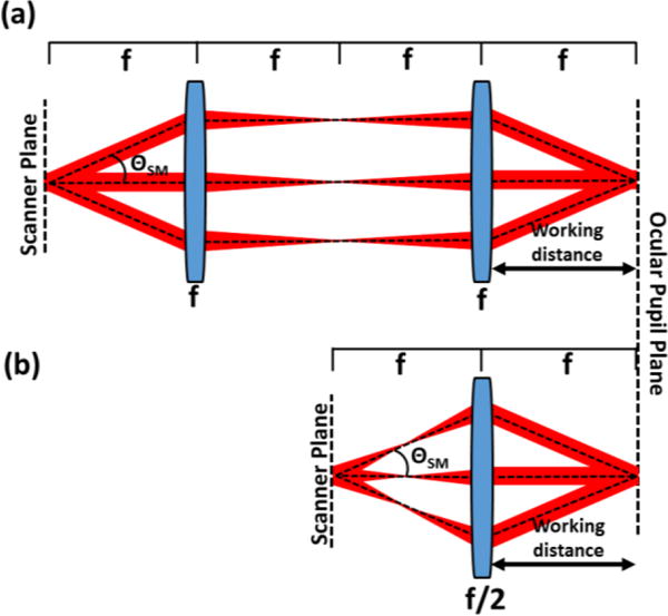
The working distance of an optical system is governed by the focal length of the last optical element and is thus tied to the total axial length of the system, which in this Letter is defined as the distance from the optical scanners to the last optical element. To increase the working distance without altering the relay magnification, the entire axial length of the optical system must be increased. In this work, we seek an optical configuration with a long working distance but a short axial length and a small footprint to facilitate clinical translation. The design parameter of interest is thus the ratio of the working distance to the axial length of the relay. A 4f afocal relay, termed 4f optical system in this Letter, uses two focusing elements to produce an image, reproducing both the position and vergence of ray bundles emerging from the object. The majority of OCT [1] and AO-SLO [6]–[8] scanners reported in the literature employ 4f systems to relay collimated light from the scanning mirrors to the ocular pupil plane (Fig. 1(a)). The working distance of the 4f system is equal to the focal length of the second element, assuming thin lenses, and is ⅓ the axial length of the relay. A 2f-2f relay, termed 2f optical system in this Letter, is an alternative relay that uses a single focusing element. 2f systems reproduce only position and not vergence of ray bundles emerging from the object in the image plane and thus require converging light incident on the scanning mirrors to relay collimated light to the ocular pupil. Multiple 2f relays have been incorporated in early SLO [9], [10] and more recent AO-SLO designs [11], although these systems still exhibited long axial lengths due to the placement of the x/y scanning mirrors on separate pupil conjugate planes and/or the need for additional pupil conjugate planes for wavefront sensing and correction. In general, retinal imaging devices using 2f systems instead of 4f systems require a smaller number of optical elements, which results in improved light transmission, less potential optical aberrations, improved signal-to-noise ratio, and simpler alignment [11]. In addition to these benefits, the working distance of an optical design that uses a single 2f relay with unity magnification is equal to the axial length of the relay (Fig. 1(b)) and therefore it can achieve the same working distance as a 4f system but in a smaller footprint. For example, if the working distances of a 2f and 4f system with unity magnification are equal, the axial length of the 2f system would be ⅓ the axial length of the 4f system, as shown in Fig. 1.
Fig 1.

Comparison of 4f afocal relays (a) and 2f relays (b) for OCT retinal imaging. The 2f system can achieve the same working distance as the 4f system but with ⅓ the relay axial length (distance from scanner to last optical element) and fewer number of required optical elements. ΘSM: scan angle.
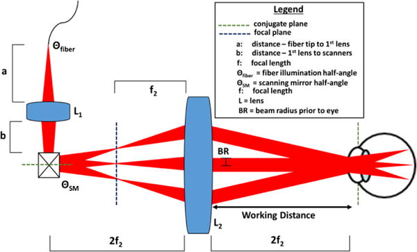
We used a single 2f refractive relay to design a long working distance OCT system with a compact form factor (Fig. 2). In this design, a beamshaping lens (L1) directed converging light through the optical scanners to a focus at a distance f2 prior to the objective (L2), resulting in collimated light incident on the cornea. The scanning mirrors were placed conjugate to the subject’s pupil at a distance 2f2 prior to the objective lens (L2). Prior to performing the detailed optical design, several parameters in our system were fixed, including the beam radius (BR) incident on the cornea, the working distance (2f2), the NA of light exiting the fiber (Θfiber) and the minimum distance (b) between L1 and the scanning mirrors. For our application we chose BR = 1.30 mm, b = 17 mm due to the physical size of the scanning mirror optomechanics, and f2 = 250 mm to achieve a maximum working distance of 500 mm. Unity magnification between the pupil and scanning mirror conjugate planes ensured that the scanning angle of the mirrors (ΘSM) was equal to the OCT FOV (defined as the angular range of light incident on the cornea). The variables used to determine the desired working distance (2f2) were the distance a from the fiber tip to L1, and f1. Using optical ray matrix transfer analysis and paraxial assumptions, the focal length of the objective f2 was approximated in terms of a, b, and f1 as:
| (1) |
Furthermore, assuming that ΘSM was not limiting, the OCT FOV was limited by the aperture of L2 as follows (using the small angle approximation):
| (2) |
where DL2 is the diameter of L2. Using Eqs. 1 and 2, f1 and a were calculated to be 8.50 mm and 8.20 mm, respectively, to yield f2 = 250 mm and DL2 = 200 mm to allow a +/− 8° OCT FOV.
Fig 2.

Schematic of a novel 2f retinal OCT scanner design enabled by delivering converging light into a single 2f refractive relay.
To optimize lateral resolution at the retinal plane, the 2f design employed two custom-designed lenses (L1 and L2) shown in Fig. 3. The lenses were designed in ray tracing software (Zemax, LLC; Kirkland, WA), and the diameter, thickness, and surface curvature of each element was optimized to minimize aberrations and achieve our design goal of 10 μm diffraction-limited lateral resolution at the retinal plane across +/− 8° FOV Achromatic doublets were chosen to minimize the optical power of each individual element and reduce chromatic aberrations. The surface curvatures and thicknesses of each element in L1 were allowed to vary during the design optimization process to achieve diffraction-limited focusing at the intermediate image plane (red line in Fig. 3(a)) using the RMS spot size as our optimization metric. Similarly, the design of L2 was optimized by allowing the curvatures, thicknesses, and distances between elements to vary to achieve collimated light at the ocular pupil plane using the RMS angular spot radius as the optimization metric. Finally, we employed a schematic eye model [12] at the ocular pupil plane and optimized both L1 and L2 using the same degrees of freedom previously noted to minimize the RMS spot size at the retinal plane. The final lens prescription of L1 is detailed in Fig. 3. During manufacturing of L2 (Shanghai Optics, Inc.; Clark, NJ), lens material optimization was performed to reduce cost without significantly altering the optical performance, and the prescription for the cost-optimized lens was proprietary to Shanghai Optics and not available for publication. The details of the L2 optical design completed at Duke University and prior to cost optimization are shown in Fig. 3. Additionally, due to the large size of L2, compensating for refractive error by axially translating the lens was impractical. Instead, the fiber tip was translated axially relative to L1 to vary the beam vergence prior to the cornea to refocus the OCT beam at the retinal plane. The optical design achieved a simulated refractive error correction range of +5 to −8 diopters by translating the fiber tip from – 0.8 mm to 1.1 mm.
Fig 3.

Optical design of the 2f sample arm. (a) Complete optical design with defined parameters and distances. (b-c) Detailed lens design of L1 (b) and L2 (before cost optimization) (c).
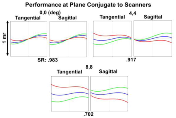
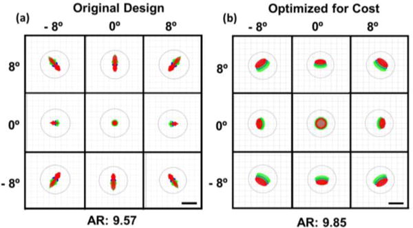
The optimized effective focal lengths (EFL) of L1 and L2 were 8.50 mm and 250 mm, respectively. The Huygens point spread functions (PSF) at the intermediate image plane were simulated and the corresponding Strehl ratios (SR) were .997 for the (0°, 0°), (4°, 4°), and (8°, 8°) field angles, indicating diffraction-limited performance. Additionally, the ray fan plots at the plane conjugate to the scanning mirrors (Fig. 4) without the schematic model eye denoted a combination of spherical and transverse chromatic aberrations present in the design. The ray aberrations however were within 1 milliradian of angular deviation from paraxial collimation, and the SRs indicated close to diffraction-limited performance before cost optimization of L2. Finally, the polychromatic geometric spot diagrams at the retinal plane of the schematic eye for the extrema of the FOV are shown in Fig. 5. Results for both the design completed at Duke University and after cost optimization are provided. While the optical performance degraded slightly after cost optimization, both designs achieved <10 μm diffraction-limited resolution over +/− 8° FOV Prominent aberrations present at the retinal plane of the schematic eye in both designs were transverse chromatic and spherical aberrations (as determined by the Seidel coefficients). The use of aspherical surfaces could reduce the residual spherical aberration but would increase the cost and complexity of the design.
Fig 4.

Simulated optical performance at the plane conjugate to the scanners without the schematic eye model and before cost optimization. The ray fan plots show the angular deviation of the rays from paraxial collimation. Deg: degree; mr: milliradian. SR: Strehl ratio. Red: 1010 nm, green: 1100 nm, blue: 1060nm.
Fig 5.

Simulated optical performance at the retinal plane of a schematic eye before (a) and after (b) cost optimization of L2. The polychromatic geometric spots are shown for the extrema of the FOV The black circles show the Airy disk, and the Airy radii (AR) are in microns. Scale bars: 10 μm. Red: 1010 nm, green: 1100 nm, blue: 1060nm
A custom-designed hot mirror with a reflectivity cutoff at 990 nm (Opcolab Laboratory, Inc.; Fitchburg, MA) and dimensions of 200 × 140 × 5 mm coupled with an LCD screen was used as a fixation target. A gold folding mirror was placed between the scanning mirrors and L2 to reduce the footprint of the system. All optical components except the folding mirror were custom-coated and the measured sample arm transmission efficiency was 68%. Custom optomechanical mounts for the folding mirror, objective, and dichroic mirror were designed and 3D printed (Fig. 6(a-b)). The resulting measured working distance, from dichroic mirror to cornea, was 349.6 mm. Additionally, a monochromatic iris camera (Point Grey Research, Inc.; Richmond, Canada) was used to facilitate subject alignment. A green marker overlayed on the displayed camera images was calibrated to demarcate the lateral position of the scan pivot. Lastly, the configuration of the custom swept-source OCT (SSOCT) system employed has been previously described [13]. Briefly, the SSOCT system used a 100 kHz, 1040 nm frequency-swept laser and achieved a peak sensitivity of 102 dB, a −6 dB sensitivity roll-off of 4.39 mm, and an average axial resolution of 8.12 μm across the entire depth range of 7.4 mm.
Fig. 6.

Representative images acquired from adult and pediatric subjects with the long working distance OCT system. (a-b) Custom optomechanical design (a) and photograph of in vivo use with iris camera frame in the top right (b). (c-d) Averaged (20 frames) B-scans centered on the fovea (c) and optic nerve (d) of a healthy adult. (e-f) Single-frame foveal B-scans acquired before (e) and after (f) refraction error correction. (g) Retinal volume acquired from a healthy adult. (h-i) Foveal B-scans acquired from patients with macular pathology. Red arrow denotes subretinal fluid in (h) and foveomacular vitelliform dystrophy in (i). (j-k) Averaged (20 frames) B-scans of the optic nerve (j) and fovea (k) of a healthy 6-year-old child.
To test our system’s imaging capability and clinical functionality, 4 healthy adults, 2 adult patients, and 1 child (6 years of age) were imaged under a protocol approved by the Duke Medical Center Institutional Review Board. The optical power incident on the cornea at 1040 nm was less than 1.7 mW, which was below the maximum permissible exposure determined by ANSI safety standards. A chin rest and slit-lamp base placed 350 mm away were used to facilitate alignment for adult imaging. During pediatric imaging, the operator gently held the child’s head for stabilization instead of using a chin rest. The operator also used the video feed from the iris camera to keep the child aligned throughout the imaging session. The imaging protocol was B-scans comprised of 800 A-scans/B-scans and volumes comprised of 800 A-scans/B-scans and 96 B-scans/volume. Subject refractive error was corrected by translating the fiber tip (mounted on a translation stage) relative to L1 and optimizing the retina to background image contrast on B-scans. Figs. 6(c-d) show averaged (20 frames) B-scans obtained from a healthy adult. Clear visualization of the choroid and inner retinal layers was achieved. Figs. 6(e-f) show single-frame B-scans before and after vergence correction for refractive error. Fig. 6(g) shows a representative volume centered on the fovea. Motion artifacts present are likely due to involuntary eye motion. Representative adult pathology images acquired with our system are shown in Figs. 6(h-i). Fig. 6(h) depicts the presence of subretinal fluid in a dilated patient, while Fig. 6(i) depicts foveomacular vitelliform dystrophy in an undilated patient. Representative pediatric optic nerve and foveal B-scans acquired are shown in Figs. 6(j-k).
Our proposed optical design used a single 2f refractive relay between the scanner and the ocular pupil to deliver collimated light to the subject’s eye. Previously reported systems that used 2f reflective relays [9]–[11] required multiple relays and out-of-plane folding to minimize the astigmatism introduced by the off-axis spherical mirrors [14]. To implement our design with reflective elements, a single aspheric mirror could be used to minimize astigmatism without the need for multiple 2f relays. The aspheric mirror would increase cost but a reflective design would result in reduced chromatic aberrations and back-reflections. However, compared to reflective designs, refractive designs may be folded more compactly, which could facilitate their clinical translation.
Incorporating ocular pupil tracking and additional scanners into our system to translate the position of the scan pivot [15] could enable automatic subject alignment. Additionally, we note that while our immediate application of the 2f system was long working distance OCT, the presented optical design could be an attractive alternative to a 4f telescope in other applications in need of compact form factors, such as handheld retinal imaging devices.
In conclusion, we have demonstrated a 2f refractive OCT retinal scanner with a working distance of 350 mm and imaged adult and pediatric subjects. Our system may facilitate OCT retinal imaging of young children with ocular diseases.
Acknowledgments
Drs. Boris Gramatikov and David Guyton (Johns Hopkins University) for fruitful discussions on the refractive error correction.
Funding. The Hartwell Foundation and NIH R01-EY023039.
Footnotes
OCIS codes: (140.4500) Optical coherence tomography, (170.4770) Ophthalmology, (170.0110) Imaging systems
References
- 1.Swanson EA, Izatt JA, Hee MR, Huang D, Lin CP, Schuman JS, Puliafito CA, Fujimoto JG. In vivo retinal imaging by optical coherence tomography. Opt Lett. 1993 Nov;18(21):1864–6. doi: 10.1364/ol.18.001864. [DOI] [PubMed] [Google Scholar]
- 2.Maldonado RS, Izatt JA, Sarin N, Wallace DK, Freedman S, Cotten CM, Toth CA. Optimizing hand-held spectral domain optical coherence tomography imaging for neonates, infants, and children. Invest Ophthalmol Vis Sci. 2010 May;51(5):2678–85. doi: 10.1167/iovs.09-4403. [DOI] [PMC free article] [PubMed] [Google Scholar]
- 3.Boppart SA, Bouma BE, Pitris C, Tearney GJ, Southern JF, Brezinski ME, Fujimoto JG. Intraoperative assessment of microsurgery with three-dimensional optical coherence tomography. Radiolog. 1998;208(1):81–86. doi: 10.1148/radiology.208.1.9646796. [DOI] [PubMed] [Google Scholar]
- 4.Tao YK, Srivastava SK, Ehlers JP. Microscope-integrated intraoperative OCT with electrically tunable focus and heads-up display for imaging of ophthalmic surgical maneuvers. Biomed Opt Expres. 2014 Jun;5(6):1877–85. doi: 10.1364/BOE.5.001877. [DOI] [PMC free article] [PubMed] [Google Scholar]
- 5.Carrasco-Zevallos OM, Keller B, Viehland C, Shen L, Waterman G, Todorich B, Shieh C, Hahn P, Kuo AN, Toth CA, Izatt JA. Live volumetric (4D) visualization and guidance of in vivo human ophthalmic microsurgery with intra-operative optical coherence tomograph. Sci Rep. 2016;6:31689-1–16. doi: 10.1038/srep31689. [DOI] [PMC free article] [PubMed] [Google Scholar]
- 6.Roorda A, Romero-Borja F, Donnelly W, III, Queener H, Hebert T, Campbell M. Adaptive optics scanning laser ophthalmoscopy. Opt Expres. 2002;10(9):405–412. doi: 10.1364/oe.10.000405. [DOI] [PubMed] [Google Scholar]
- 7.Merino D, Dainty C, Bradu A, Podoleanu AG. Adaptive optics enhanced simultaneous en-face optical coherence tomography and scanning laser ophthalmoscopy. Opt Expres. 2006;14(8):3345–3353. doi: 10.1364/oe.14.003345. [DOI] [PubMed] [Google Scholar]
- 8.Hammer DX, Ferguson RD, Bigelow CE, Iftimia NV, Ustun TE, Burns SA. Adaptive optics scanning laser ophthalmoscope for stabilized retinal imaging. Opt Expres. 2006;14(8):3354–3367. doi: 10.1364/oe.14.003354. [DOI] [PMC free article] [PubMed] [Google Scholar]
- 9.Webb RH, Hughes GW, Delori FC. Confocal scanning laser ophthalmoscop. Appl Opt. 1987;26(8):1492–1499. doi: 10.1364/AO.26.001492. [DOI] [PubMed] [Google Scholar]
- 10.Sharp PF, Manivannan A. The scanning laser ophthalmascop. Phys Med Biol. 1997;42:951–966. doi: 10.1088/0031-9155/42/5/014. [DOI] [PubMed] [Google Scholar]
- 11.Dubra A, Gomez-Vieyra A, Sulai Y, Díaz-Santana L. Optical Design of Clinical Adaptive Optics Instruments for Retinal Imagin. OSA Technical Digest, Frontiers in Optics. 2010:1–2. [Google Scholar]
- 12.Goncharov AV, Dainty C. Wide-field schematic eye models with gradient-index len. J Opt Soc Am. 2007;24(8):2157–2174. doi: 10.1364/josaa.24.002157. [DOI] [PubMed] [Google Scholar]
- 13.Viehland C, Keller B, Carrasco-Zevallos OM, Nankivil D, Shen L, Mangalesh S, Tran-Viet D, Kuo AN, Toth CA, Izatt JA. Enhanced volumetric visualization for real time 4D intraoperative ophthalmic swept-source OC. Biomed Opt Expres. 2016;7(5):1815–29. doi: 10.1364/BOE.7.001815. [DOI] [PMC free article] [PubMed] [Google Scholar]
- 14.Gómez-Vieyra A, Dubra A, Malacara-Hernández D, Williams DR. First-order design of off-axis reflective ophthalmic adaptive optics systems using afocal telescopes. Opt Expres. 2009 Oct;17(21):18906–19. doi: 10.1364/OE.17.018906. [DOI] [PMC free article] [PubMed] [Google Scholar]
- 15.Carrasco-Zevallos OM, Nankivil D, Keller B, Viehland C, Lujan BJ, Izatt JA. Pupil tracking optical coherence tomography for precise control of pupil entry positio. Biomed Opt Expres. 2015;6(9):3405–19. doi: 10.1364/BOE.6.003405. [DOI] [PMC free article] [PubMed] [Google Scholar]


