Abstract
We describe a long axial field-of-view (FOV) PET scanner for high-sensitivity and total-body imaging of nonhuman primates and present the physical performance and first phantom and animal imaging results. Methods: The mini-EXPLORER PET scanner was built using the components of a clinical scanner reconfigured with a detector ring diameter of 43.5 cm and an axial length of 45.7 cm. National Electrical Manufacturers Association (NEMA) NU-2 and NU-4 phantoms were used to measure sensitivity and count rate performance. Reconstructed spatial resolution was investigated by imaging a radially stepped point source and a Derenzo phantom. The effect of the wide acceptance angle was investigated by comparing performance with maximum acceptance angles of 14°–46°. Lastly, an initial assessment of the in vivo performance of the mini-EXPLORER was undertaken with a dynamic 18F-FDG nonhuman primate (rhesus monkey) imaging study. Results: The NU-2 total sensitivity was 5.0%, and the peak noise-equivalent count rate measured with the NU-4 monkey scatter phantom was 1,741 kcps, both obtained using the maximum acceptance angle (46°). The NU-4 scatter fraction was 16.5%, less than 1% higher than with a 14° acceptance angle. The reconstructed spatial resolution was approximately 3.0 mm at the center of the FOV, with a minor loss in axial spatial resolution (0.5 mm) when the acceptance angle increased from 14° to 46°. The rhesus monkey 18F-FDG study demonstrated the benefit of the high sensitivity of the mini-EXPLORER, including fast imaging (1-s early frames), excellent image quality (30-s and 5-min frames), and late-time-point imaging (18 h after injection), all obtained at a single bed position that captured the major organs of the rhesus monkey. Conclusion: This study demonstrated the physical performance and imaging capabilities of a long axial FOV PET scanner designed for high-sensitivity imaging of nonhuman primates. Further, the results of this study suggest that a wide acceptance angle can be used with a long axial FOV scanner to maximize sensitivity while introducing only minor trade-offs such as a small increase in scatter fraction and slightly degraded axial spatial resolution.
Keywords: positron emission tomography, high sensitivity, long axial field of view, total-body imaging, rhesus monkey
One of the major limitations of PET is the relatively low number of 511-keV coincidence events collected during the scan. This constraint is often the major source of image noise and limits temporal precision in dynamic imaging studies. Along with effects such as photon attenuation in the subject and limitations on the radiation dose for patient safety, the sensitivity of the PET scanner strongly influences the number of coincidences collected during the scan. The short axial length of most modern PET systems is a key factor limiting sensitivity (1). A short scanner collects annihilation photons from only a small portion of the subject, requiring multiple bed positions to acquire a whole-body image, and limits the geometric detection efficiency (solid angle) for the isotopically emitted annihilation photons.
There is growing interest in developing PET scanners with a larger axial field-of-view (FOV) for high-sensitivity and total-body imaging (2–5). Several studies have investigated the feasibility and factors affecting the performance of long axial FOV PET systems (5–14), quantifying the impact of an extended axial FOV for various imaging tasks (15–17) and describing the potential role of high-sensitivity, total-body PET in clinical and research applications (2,18,19). These studies suggest that extending the axial FOV will provide increased image signal-to-noise ratio, better quantitative accuracy, improved detection of small lesions, and improved temporal resolution and body coverage for dynamic PET, including enabling kinetic modeling in multiple organs simultaneously.
In this work, we describe the development and performance of a long axial FOV PET scanner for imaging nonhuman primates. The physiologic and evolutionary relatedness between humans and nonhuman primates supports rhesus monkeys as a suitable animal model in several areas of biomedical research, including neuroscience, immunology, infectious disease, health across the life span (fetal to aged), regenerative medicine, and drug discovery (20–26).
To enable high-sensitivity total-body PET imaging of nonhuman primates, we have constructed a long axial FOV scanner with a bore size suitable for rhesus monkeys (27). The scanner, called the mini-EXPLORER, was built by rearranging the detectors from a clinical scanner (Biograph mCT; Siemens (28)) into a scanner with a smaller bore diameter but longer axial length, suitable for total-body rhesus monkey imaging. The mini-EXPLORER is installed in the Multimodal Imaging Core at the California National Primate Research Center.
This study addresses two aims. First, we characterize the physical performance and image quality of the mini-EXPLORER using imaging phantoms and demonstrate the initial in vivo imaging capabilities with a 18F-FDG dynamic imaging study with a rhesus monkey. Second, we examine the effect of the wide acceptance angle on scanner performance. The mini-EXPLORER has the largest acceptance angle of any PET scanner built to date; thus, it is informative to evaluate the change in scanner performance in this new regime.
MATERIALS AND METHODS
Scanner Description
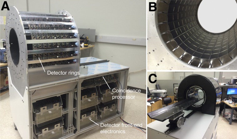
The mini-EXPLORER (Fig. 1) was built using the detectors and electronics from a clinical scanner (prototype for the Siemens Biograph mCT (28)). The 192 detectors, originally arranged in 4 rings in the clinical scanner, were rearranged into 8 rings in the mini-EXPLORER, leading to a ring diameter of 43.5 cm and an axial length of 45.7 cm. The physical characteristics of the mini-EXPLORER are summarized in Table 1. Each detector contains a 13 × 13 array of lutetium oxyorthosilicate (LSO) scintillator crystals (4.0-mm crystal pitch, 20-mm length) coupled via a 12-mm-thick light guide to 4 photomultiplier tubes (Hamamatsu R9800) in a conventional PET block detector configuration (29). The analog photomultiplier tube signals are routed via 2-m-long Ethernet cables to the front-end electronics, which are housed in the gantry below the detector rings. Each front-end electronics unit processes detector signals from a bank of 16 detectors (2 transaxial × 8 axial) and computes the energy, position, and time of the photon interaction in the detector. Events passing the specified energy window are passed to the coincidence processor for coincidence detection.
FIGURE 1.
(A) Side view of scanner with covers removed showing gantry frame, detector rings, and scanner electronics. (B) View inside detector rings showing detectors mounted between tapered aluminum rails. (C) View from front of scanner with covers on and scanning bed installed.
TABLE 1.
Physical Characteristics of mini-EXPLORER
| Parameter | Description |
| Photodetector | Photomultiplier tube |
| Scintillator | Lutetium oxyorthosilicate |
| Crystal pitch | 4 × 4 × 20 mm |
| Total number of crystals | 32,448 |
| Detector ring diameter | 43.5 cm |
| Transaxial FOV | 32.0 cm |
| Axial FOV | 45.7 cm |
Tapered aluminum rails were fabricated for mounting the detectors in 8 rings and were fastened at their ends to flanges made of cast aluminum tooling plates. The detector ring assembly is supported by an aluminum frame, which also houses the electronics and cabling. Ambient room temperature air is circulated around the outside of the detectors to maintain a stable detector temperature, using a thermostat-controlled fan to modulate the air flow. The scanner bed was built using a 12-mm-thick structural foam core (Rohacell 31) surrounded by 7 layers of carbon fiber (twill weave, 200 g/m2) and epoxy resin (West System 105). Two carbon rods were extruded through the bed near the edges for reinforcement.
List-mode data containing both prompt and delayed coincidences (for random-coincidence correction) are sent via a fiber-optic link to the host personal computer. Each coincidence event is a 64-bit word containing the coincidence crystal indices, the time-of-flight value (78-ps precision), and a tag indicating whether the event is a prompt coincidence or a delayed coincidence (for random-coincidence estimation). The coincidence firmware was not modified from the original clinical prototype system; instead, the crystal indices were remapped to the new 8-ring scanner geometry in postprocessing.
Scanner Calibration and Tuning
Custom software was used to segment flood histograms and identify the 511-keV energy peak in energy histograms using a 68Ge source placed near the center of the FOV. Event positions and the energy of single events were acquired directly from the detector front-end electronics using the singles pass-through mode of the coincidence processor. An automated peak-finding algorithm was used to identify crystal positions in the flood histogram and the 511-keV peak in the energy spectra for each crystal. The flood histograms and 511-keV peak positions were periodically recalibrated throughout the course of this study.
Timing alignment for each crystal was performed using the iterative fan-beam method described by Casey (30), using coincidence data collected from a 50-cm-long, 10-cm-diameter cylinder filled with water plus 18F-FDG (∼10 MBq).
Physical Performance
Data Acquisition Parameters
The physical performance of the mini-EXPLORER was characterized for 4 acceptance angles—46°, 37°, 27°, and 14°—corresponding to maximum block detector differences of 8, 6, 4, and 2 rings, respectively. The acceptance angles (maximum ring difference) were applied in postprocessing; setting the maximum ring difference in the coincidence firmware was not possible because of the modified scanner geometry. A 425- to 650-keV energy window was used for all measurements.
A variable timing window was implemented to account for the relatively large difference in maximum time-of-flight values between the direct and most oblique lines of response (6,31) and calculated according to Equation 1:
| Eq. 1 |
where is the transaxial FOV (32 cm), is the acceptance angle (or angle corresponding to the ring difference for a single event), is the coincidence timing resolution (609 ps), and is the speed of light in a vacuum. The maximum coincidence timing windows for each acceptance angle were 3.6, 3.3, 3.05, and 2.8 ns for the 46°, 37°, 27°, and 14° acceptance angles, respectively.
Sensitivity
The sensitivity of the mini-EXPLORER was measured according to the National Electrical Manufacturers Association (NEMA) NU-2 2012 protocol. The 700-mm line source was filled with 8 MBq of 18F-FDG aqueous solution, and list-mode data were acquired for 600 s for each of the 5 aluminum sleeves. The list-mode data were rebinned into direct plane sinograms (2-mm slice thickness) using single-slice rebinning for both prompt and delayed coincidences, and the delayed-coincidence sinogram was subtracted from the prompt sinogram.
Count Rate Performance, Noise-Equivalent Count Rate (NECR), and Scatter Fraction
Count rate performance was measured using the NEMA NU-4 2008 monkey scatter phantom. The NU-4 monkey scatter phantom is a 100-mm-diameter and 400-mm-long polyethylene cylinder with a 1.8-mm-diameter line source threaded through the cylinder at a 30-mm radial offset. The line source was filled with 270 MBq of 18F-FDG, and list-mode data were acquired for 300 s at 1,200-s intervals for each of the 4 acceptance angles over 16 h. Prompt- and delayed-coincidence sinograms were generated from the list-mode data and rebinned using single-slice rebinning. True-, scatter-, and random-coincidence rates were extracted from the rebinned sinograms as described in the NEMA NU-4 protocol. Time-of-flight information was not used in these measurements.
Count rate data with the NU-4 monkey scatter phantom were also acquired on a standard Biograph mCT scanner (Northern California PET Imaging Center, Sacramento, CA), and, for completeness, NECR and scatter fraction were also measured with the clinical NU2-2012 scatter phantom.
Imaging Studies
Image Reconstruction
A 3-dimensional list-mode ordered-subsets expectation-maximization algorithm with time-of-flight capability was implemented for image reconstruction. The system matrix included an accurate resolution model via multiray tracing for each line of response (32). All images were reconstructed with a 1.0 × 1.0 × 1.0 mm voxel size. All reconstructed images were obtained using 3 iterations and 13 subsets.
Data Corrections
Attenuation, normalization, and random-coincidence corrections were included in the forward-projection model of the reconstruction. Attenuation maps for 511 keV were derived from coregistered CT images using the bilinear scaling method to scale Hounsfield units to 511-keV attenuation coefficients (33). CT images were acquired on a 64-slice clinical scanner (Discovery 610; GE Healthcare) at 120 kVp. Component-based normalization was performed using an iterative model–based algorithm (34), with an annular phantom used to acquire the normalization data (Supplemental Fig. 1; supplemental materials are available at http://jnm.snmjournals.org). Random-coincidence correction was performed using the delayed-coincidence sinogram and a model-based method, similar to the normalization algorithm, to produce a reduced-variance estimate of the random-coincidence mean for each prompt list-mode event. No scatter correction was used in this study.
Uniform Cylinder
A 10-cm-diameter and 50-cm-long uniform cylinder phantom was constructed from a hollow acrylic cylinder and used to assess reconstructed image uniformity. The cylinder was positioned in the center of the FOV, filled with approximately 10 MBq of 18F-FDG aqueous solution, and imaged for 1,200 s.
Reconstructed Spatial Resolution
Reconstructed point-source spatial resolution was calculated by imaging a 0.25-mm 22Na point source contained in a resin disk. The source was positioned at a 20-mm axial offset from the center of the FOV and stepped radially in 10-mm increments. The point-source data were reconstructed in a warm background provided by a 20-cm-diameter cylinder filled with 18F-FDG, followed by subtracting the cylinder image. Radial, tangential, and axial line profiles through each point-source position were fit with gaussian distributions to calculate spatial resolution.
A Derenzo phantom (Supplemental Fig. 2), containing 6 groups of activity-filled rods with diameters from 2 to 7 mm, was also imaged to evaluate spatial resolution. The phantom was filled with 8 MBq of 18F-FDG aqueous solution (44 kBq/mL) and imaged for 600 s.
Nonhuman Primate Imaging
All animal procedures conformed to the requirements of the Animal Welfare Act, and protocols were approved by the Institutional Animal Care and Use Committee at the University of California–Davis. A young female rhesus monkey (4.5 y, 5.4 kg) was sedated with an intramuscular injection of Telazol (8 mg/kg) supplemented with ketamine (5–10 mg/kg). The animal was placed on the scanner bed, injected intravenously with 92.5 MBq of 18F-FDG (∼1 mL), and imaged dynamically for 60 min in a single bed position. Data acquisition was initiated about 5 s before the 18F-FDG injection. The same animal was imaged at 18 h after injection under the same conditions with a 40-min single-bed-position scan. After PET imaging, the animal (on the scanner bed) was moved to the CT scanner and imaged. At the completion of imaging, the animal was returned to housing and recovered uneventfully.
RESULTS
Physical Performance
A summary of the NEMA physical performance evaluation of the mini-EXPLORER scanner is shown in Table 2.
TABLE 2.
Physical Performance of mini-EXPLORER
| Parameter | Acceptance angle |
|||
| 14° | 27° | 37° | 46° | |
| NU-2 sensitivity (%) | 2.4 | 4.0 | 4.8 | 5.0 |
| NU-4 peak monkey NECR (kcps) | 895 | 1,466 | 1,707 | 1,741 |
| NU-4 scatter fraction (%) | 15.6 | 16.1 | 16.4 | 16.5 |
Sensitivity
Axial sensitivity profiles are shown in Figure 2 for the 46° acceptance angle, demonstrating an NU-2 total sensitivity of 5.0% and a peak sensitivity of about 15% at the center of the FOV. Total NU-2 2012 sensitivities for all acceptance angles are provided in Table 2. For all acceptance angles, sensitivity was consistently about 1.03 times higher at the radial center than at the 10-cm radial offset. The NU-2 sensitivity of the Biograph mCT scanner was 0.97% (28), corresponding to a 5.1-fold increase in sensitivity with the mini-EXPLORER compared with the Biograph mCT. This measured sensitivity gain agrees closely with the increase in geometric solid-angle coverage of the mini-EXPLORER relative to the Biograph mCT (5.2-fold increase).
FIGURE 2.
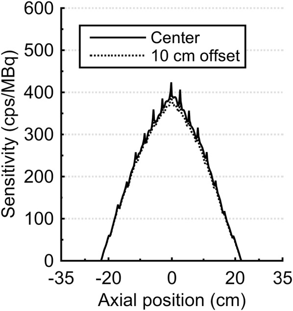
Axial NEMA NU-2 sensitivity profiles (2-mm axial slices) obtained with 46° acceptance angle.
Count Rate Performance
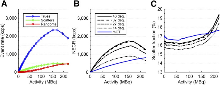
True-, scatter-, and random-coincidence rates obtained from the NU-4 monkey scatter phantom are plotted in Figure 3A for the 46° acceptance angle. The small diameter of the NU-4 monkey phantom and the full axial coverage of the phantom by the axial FOV led to a high true-coincidence rate relative to scatter and random coincidences. The count rate performance with the NU-2 scatter phantom is provided in Supplemental Figure 3A.
FIGURE 3.
NEMA NU-4 monkey scatter phantom count rate performance. (A) True-, scatter-, and random-coincidence rates measured with 46° acceptance angle. (B) NECR vs. activity for each acceptance angle. (C) Scatter fraction vs. activity for each acceptance angle.
NECR
NECR is plotted in Figure 3B for all 4 acceptance angles. The 46° angle provided the highest NECR at all levels of radioactivity, with a peak NECR of 1,741 kcps at a 158-MBq activity. The peak NECR occurred between 150 and 160 MBq for all acceptance angles. Use of the variable timing window had only a minor effect on NECR, providing at most a 2.5% increase in NU-4 peak NECR with the 46° acceptance angle. This result was likely due to the limited transaxial FOV used in the count rate measurements as specified in the NEMA NU-4 protocol (11.6-cm diameter). With the NU-2 scatter phantom (NECR in Supplemental Fig. 3B), the variable timing window provided a maximum 6.0% increase in NECR with the 46° acceptance angle.
Scatter Fraction
Scatter fraction for each acceptance angle is plotted in Figure 3C. As expected, scatter fraction was nearly constant at low activity for all acceptance angles, after which the measured scatter fraction quickly increased, coinciding with the decrease in NECR. The increase in scatter fraction resulted from pulse pile-up in the detectors, leading to mispositioning of events in the block detectors and bias in the energy estimation.
The average scatter fraction for each acceptance angle was computed up to the corresponding peak NECR activity and is summarized in Table 2, showing less than a 1% change in average scatter fraction across all acceptance angles. Consistent results were obtained with the NU-2 scatter phantom (Supplemental Fig. 3C).
The lower scatter fraction (both NU-4 and NU-2) measured with the mini-EXPLORER than with the Biograph mCT may be a result of the smaller detector ring diameter. For a scattered event with a given scattering angle, there will be a smaller positioning error from the true line of response for a smaller ring diameter than for a larger ring diameter, analogous to event mispositioning from photon noncollinearity. Additionally, differences between the scanners (minor differences in electronics or the patient bed) may also affect the scatter fraction results.
Imaging Studies
Image Uniformity
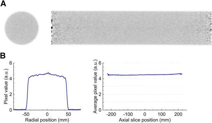
Transaxial and sagittal slices of the reconstructed uniform cylinder phantom (46° acceptance angle) are shown in Figure 4. The full data set contained about 500 million prompt coincidences, with an average random-coincidence fraction of about 5%. Both slices showed excellent uniformity, and no discernable artifacts were present. A radial line profile extracted from the sum of all transaxial image slices is shown in Figure 4B, demonstrating the recovery of the uniform activity distribution and the efficacy of the data corrections. Figure 4B also shows the average image value inside the uniform cylinder (10-cm-diameter region concentric with the phantom) for each axial image slice. The SD of the average axial values was 0.8%.
FIGURE 4.
(A) Transaxial (left) and sagittal (right) image slices of reconstructed uniform cylinder. (B) Radial line profile through average of all transaxial image slices (left) and average image pixel value inside uniform cylinder for each axial slice (right).
Spatial Resolution
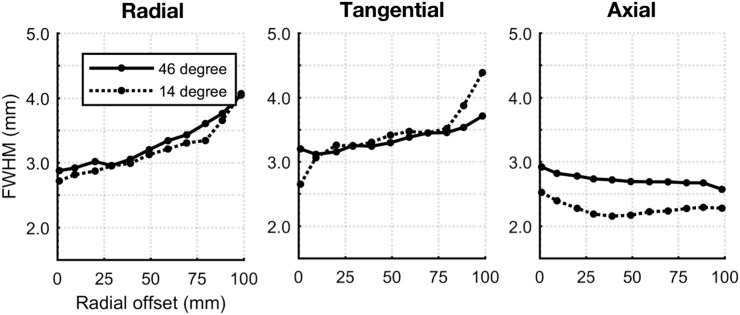
Reconstructed point-source spatial resolutions in the radial, tangential, and axial directions are shown in Figure 5. At the center of the FOV, the spatial resolution was approximately 3 mm at full width at half maximum in all directions. Use of a 14° acceptance angle had no significant effect on radial or tangential resolution but resulted in an approximately 0.5-mm improvement in axial spatial resolution compared with the 46° acceptance angle.
FIGURE 5.
Reconstructed point-source spatial resolution vs. radial offset.
A transaxial slice of the reconstructed image of the Derenzo phantom is shown in Figure 6. The image was reconstructed using the 46° acceptance angle and contains approximately 400 million prompt coincidences with an average random-coincidence fraction of 5%. All rods except for the 2-mm group could be clearly resolved, and there were no discernable artifacts in the image.
FIGURE 6.
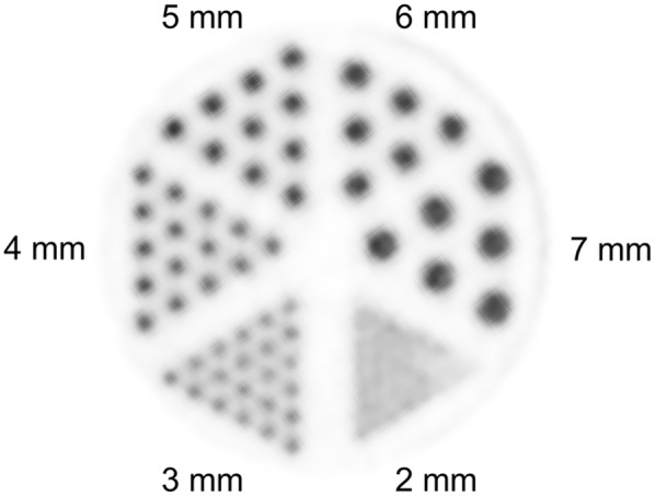
Transaxial slice of Derenzo phantom reconstructed image.
Rhesus Monkey Imaging
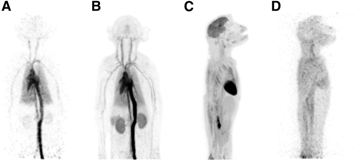
Reconstructed maximum-intensity-projection images are shown in Figure 7, highlighting the benefit of the long axial FOV and high sensitivity. The early 18F-FDG distribution in major blood vessels and organs was able to be visualized with 1-s frames (Fig. 7A); excellent image quality was demonstrated for both an early frame (first 30 s after injection [Fig. 7B]) and a late frame (55–60 min after injection [Fig. 7C]); and reasonable image quality, sufficient to identify several features, was obtained in a 40-min scan at 18 h after injection (Fig. 7D), representing approximately 10 half-lives after injection (and a maximum activity in the animal, ignoring any excretion, of just 0.1 MBq).
FIGURE 7.
Maximum-intensity-projection images from 18F-FDG rhesus monkey study: 1-s frame at 5 s after injection (reconstructed using kernel method (37)) (A), 0–30 s after injection (B), 55–60 min after injection (C), and 18 h after injection (40-min scan) (D). Further images are provided as Supplemental Figure 4 and Supplemental Videos 1–6.
DISCUSSION
In this study, we described and evaluated the mini-EXPLORER, a long axial FOV PET scanner designed for high-sensitivity imaging of nonhuman primates. The major benefits of the long axial FOV and wide acceptance angle observed here were substantial gains in sensitivity and NECR: the largest acceptance angle (46°) provided an approximately 2.5-fold-higher sensitivity than the smallest acceptance angle (14°) and an approximately 5-fold-higher sensitivity than the original Biograph mCT scanner. The NU-4 monkey scatter fraction showed a small trade-off with acceptance angle, where scatter fraction measured with the 46° acceptance angle was about 1% higher than with a 14° acceptance angle. This relatively small increase in scatter fraction for larger acceptance angles may appear somewhat counterintuitive since oblique sinograms contain higher numbers of scatter events (35); however, the number of additional sinograms diminishes with increasing acceptance angle and so the overall scatter fraction is minimally affected by increasing acceptance angle, as demonstrated previously in simulations (10,35). Lastly, we measured the effect of the acceptance angle on spatial resolution by imaging a point source in a warm background, as it has been suggested that parallax error from depth-of-interaction effects and blurring from photon noncollinearity may increase in a scanner with a wide acceptance angle, leading to degraded axial spatial resolution (7,36). However, there was only minor degradation in axial spatial resolution (0.5 mm in full width at half maximum) at a 46° acceptance angle, compared with a 14° acceptance angle, in agreement with the simulation results shown by Schmall et al. (7). Therefore, the data suggest that the full 46° acceptance angle in the mini-EXPLORER can be used to substantially increase sensitivity while introducing only minor trade-offs in physical performance compared with a reduced acceptance angle (i.e., 14°). However, these measures may not fully represent all changes that affect image quality with a long axial FOV scanner, and ultimately, the optimal acceptance angle may be task-dependent.
The limitations of this study in predicting the effect of a wide acceptance angle in other long axial FOV scanners should be acknowledged. In the mini-EXPLORER, the 46° acceptance angle is used in only the center of the axial FOV, whereas in a longer scanner, such as the proposed human EXPLORER scanner with a 200-cm axial length and maximum acceptance angle of about 70°, a 46° acceptance angle would be used in the central 115 cm of the FOV. Therefore, it is difficult to extrapolate the relationships between sensitivity and count rate performance versus acceptance angle shown here. Additionally, the narrower bore of the mini-EXPLORER results in increased dead time and pile-up compared with a scanner with a wider detector-ring diameter, with the result being that maximum count rates are reached at lower activity concentrations than for the Biograph mCT scanner.
Lastly, excellent image quality was achieved both in the phantom imaging experiments and in the 18F-FDG dynamic study with a rhesus monkey, where the long axial FOV enabled most of the major organs to be imaged at a single bed position, and the high sensitivity provided the ability for fast dynamic imaging, excellent image quality for both early and late frames of the 60-min dynamic scan, and reasonable image quality at 18 h after injection. To our knowledge, this is the first time the distribution of 18F-FDG has been imaged at more than 10 h after injection.
Although the 45-cm axial FOV allowed imaging of most of the animal’s body at a single bed position, it did not capture the full torso and lower limbs of this young nonhuman primate. However, the gantry construction allows for a maximum 60-cm axial FOV by introducing small gaps (≤2 cm) between the detector rings. Extending the axial FOV by increasing the gap between detector rings will be investigated in future work, including the effect of axial gaps on image quality and data corrections (i.e., normalization).
CONCLUSION
In this work, we described a long axial FOV PET scanner (mini-EXPLORER) designed to image nonhuman primates with high sensitivity. The scanner demonstrated 5.0% NU-2 total sensitivity, along with a peak NU-4 (monkey) NECR of 1,741 kcps, a scatter fraction of 16.5%, and isotropic spatial resolution of about 3 mm at the center of the FOV. The imaging capabilities of the mini-EXPLORER were showcased with a 18F-FDG monkey imaging study, demonstrating the benefit of long axial FOV PET for fast dynamic imaging, high image signal-to-noise ratio, and imaging very low activity concentrations.
DISCLOSURE
Funding was provided by the Natural Sciences and Engineering Research Council of Canada (NSERC), a UC Davis Research Investments in Science and Engineering (RISE) grant, and NIH grants P51 OD011107 (Primate Center base operating grant) and R01 CA206187. No other potential conflict of interest relevant to this article was reported.
Supplementary Material
Acknowledgments
This study was led by Eric Berg (system design, testing, and characterization), Xuezhu Zhang (data corrections and image reconstruction), and Julien Bec (mechanical design and engineering). We thank Bruce Finley and Ruth Tesar of the Northern California PET Imaging Center for assistance with acquiring phantom data on the Biograph mCT scanner, and the Primate Center Multimodal Imaging Core for assistance with in vivo imaging.
REFERENCES
- 1.Cherry SR. The 2006 Henry N. Wagner Lecture: of mice and men (and positrons)—advances in PET imaging technology. J Nucl Med. 2006;47:1735–1745. [PubMed] [Google Scholar]
- 2.Cherry SR, Badawi RD, Karp J, Moses WW, Price PM, Jones T. Total-body imaging: transforming the role of PET in translational medicine. Sci Transl Med. 2017;9:eaaf6169. [DOI] [PMC free article] [PubMed] [Google Scholar]
- 3.Cherry SR, Jones T, Karp JS, Qi J, Moses WW, Badawi RD. Total-body PET: maximizing sensitivity to create new opportunities for clinical research and patient care. J Nucl Med. 2018;59:3–12. [DOI] [PMC free article] [PubMed] [Google Scholar]
- 4.Crespo P, Reis J, Couceiro M, et al. Whole-body single-bed time-of-flight RPC-PET: simulation of axial and planar sensitivities with NEMA and anthropomorphic phantoms. IEEE Trans Nucl Sci. 2012;59:520–529. [Google Scholar]
- 5.Wong W-H, Zhang Y, Liu S, et al. The initial design and feasibility study of an affordable high-resolution 100-cm long PET. In: Yu B, ed. 2007 IEEE Nuclear Science Symposium Conference Record. Vol. 6 Piscataway, NJ: IEEE; 2007: 4117. [Google Scholar]
- 6.Poon JK, Dahlbom ML, Moses WW, et al. Optimal whole-body PET scanner configurations for different volumes of LSO scintillator: a simulation study. Phys Med Biol. 2012;57:4077–4094. [DOI] [PMC free article] [PubMed] [Google Scholar]
- 7.Schmall JP, Karp JS, Werner M, Surti S. Parallax error in long-axial field-of-view PET scanners: a simulation study. Phys Med Biol. 2016;61:5443–5455. [DOI] [PMC free article] [PubMed] [Google Scholar]
- 8.Surti S, Karp J. Impact of detector design on imaging performance of a long axial field-of-view, whole-body PET scanner. Phys Med Biol. 2015;60:5343–5358. [DOI] [PMC free article] [PubMed] [Google Scholar]
- 9.Thoen H, Keereman V, Mollet P, Van Holen R, Vandenberghe S. Influence of detector pixel size, TOF resolution and DOI on image quality in MR-compatible whole-body PET. Phys Med Biol. 2013;58:6459–6479. [DOI] [PubMed] [Google Scholar]
- 10.Badawi RD, Kohlmyer S, Harrison R, Vannoy S, Lewellen T. The effect of camera geometry on singles flux, scatter fraction and trues and randoms sensitivity for cylindrical 3D PET: a simulation study. IEEE Trans Nucl Sci. 2000;47:1228–1232. [Google Scholar]
- 11.Borasi G, Fioroni F, Del Guerra A, Lucignani G. PET systems: the value of added length. Eur J Nucl Med Mol Imaging. 2010;37:1629–1632. [DOI] [PubMed] [Google Scholar]
- 12.Couceiro M, Ferreira N, Fonte P. Sensitivity assessment of wide axial field of view PET systems via Monte Carlo simulations of NEMA-like measurements. Nucl Instrum Methods Phys Res A. 2007;580:485–488. [Google Scholar]
- 13.Eriksson L, Townsend D, Conti M, et al. An investigation of sensitivity limits in PET scanners. Nucl Instrum Methods Phys Res A. 2007;580:836–842. [Google Scholar]
- 14.MacDonald LR, Harrison R, Alessio A, Hunter W, Lewellen T, Kinahan P. Effective count rates for PET scanners with reduced and extended axial field of view. Phys Med Biol. 2011;56:3629–3643. [DOI] [PMC free article] [PubMed] [Google Scholar]
- 15.Surti S, Werner M, Karp J. Study of PET scanner designs using clinical metrics to optimize the scanner axial FOV and crystal thickness. Phys Med Biol. 2013;58:3995–4012. [DOI] [PMC free article] [PubMed] [Google Scholar]
- 16.Thoen H, Keereman V, Mollet P, Van Holen R, Vandenberghe S. Influence of detector parameters on lesion detectability for PET scanners with long axial FOV [abstract]. J Nucl Med. 2014;55(suppl 1):2153. [Google Scholar]
- 17.Zhang X, Zhou J, Wang G, et al. Feasibility study of micro-dose total-body dynamic PET imaging using the EXPLORER scanner [abstract]. J Nucl Med. 2014;55(suppl 1):269. [Google Scholar]
- 18.Jones T, Budinger TF. The potential for low-dose functional studies in maternal–fetal medicine using PET/MR imaging. J Nucl Med. 2013;54:2016–2017. [DOI] [PubMed] [Google Scholar]
- 19.Price PM, Badawi RD, Cherry SR, Jones T. Ultra staging to unmask the prescribing of adjuvant therapy in cancer patients: the future opportunity to image micrometastases using total-body 18F-FDG PET scanning. J Nucl Med. 2014;55:696–697. [DOI] [PMC free article] [PubMed] [Google Scholar]
- 20.Baker CA, Swainson L, Lin DL, et al. Exposure to SIV in utero results in reduced viral loads and altered responsiveness to postnatal challenge. Sci Transl Med. 2015;7:300ra125. [DOI] [PMC free article] [PubMed] [Google Scholar]
- 21.Benveniste H, Fowler JS, Rooney WD, et al. Maternal-fetal in vivo imaging: a combined PET and MRI study. J Nucl Med. 2003;44:1522–1530. [PubMed] [Google Scholar]
- 22.Capitanio JP, Emborg ME. Contributions of non-human primates to neuroscience research. Lancet. 2008;371:1126–1135. [DOI] [PubMed] [Google Scholar]
- 23.Howell LL, Murnane KS. Nonhuman primate positron emission tomography neuroimaging in drug abuse research. J Pharmacol Exp Ther. 2011;337:324–334. [DOI] [PMC free article] [PubMed] [Google Scholar]
- 24.Santangelo PJ, Rogers KA, Zurla C, et al. Whole-body immunoPET reveals active SIV dynamics in viremic and antiretroviral therapy-treated macaques. Nat Methods. 2015;12:427–432. [DOI] [PMC free article] [PubMed] [Google Scholar]
- 25.Tarantal AF, Lee CCI, Jimenez DF, Cherry SR. Fetal gene transfer using lentiviral vectors: in vivo detection of gene expression by microPET and optical imaging in fetal and infant monkeys. Hum Gene Ther. 2006;17:1254–1261. [DOI] [PubMed] [Google Scholar]
- 26.Tarantal AF, Lee CCI, Kukis DL, Cherry SR. Radiolabeling human peripheral blood stem cells for positron emission tomography (PET) imaging in young rhesus monkeys. PLoS One. 2013;8:e77148. [DOI] [PMC free article] [PubMed] [Google Scholar]
- 27.Catchpole HR, Van Wagenen G. Physical growth of the rhesus monkey (Macaca mulatta). Am J Phys Anthropol. 1956;14:245–273. [DOI] [PubMed] [Google Scholar]
- 28.Jakoby BW, Bercier Y, Conti M, Casey ME, Bendriem B, Townsend DW. Physical and clinical performance of the mCT time-of-flight PET/CT scanner. Phys Med Biol. 2011;56:2375–2389. [DOI] [PubMed] [Google Scholar]
- 29.Casey M, Nutt R. A multicrystal two dimensional BGO detector system for positron emission tomography. IEEE Trans Nucl Sci. 1986;1:460–463. [Google Scholar]
- 30. Casey ME, Chen M, Gremillion TG, Hayden CH, Lenox MW, Panin VY. Systems and methods for calibrating time alignment for a positron emission tomography (PET) system. US Patents; 2012.
- 31.Conti M. Tailoring PET time coincidence window using CT morphological information. IEEE Trans Nucl Sci. 2007;54:1599–1605. [Google Scholar]
- 32.Huesman RH, Klein GJ, Moses WW, Qi J, Reutter BW, Virador PR. List-mode maximum-likelihood reconstruction applied to positron emission mammography (PEM) with irregular sampling. IEEE Trans Med Imaging. 2000;19:532–537. [DOI] [PubMed] [Google Scholar]
- 33.Carney JP, Townsend DW, Rappoport V, Bendriem B. Method for transforming CT images for attenuation correction in PET/CT imaging. Med Phys. 2006;33:976–983. [DOI] [PubMed] [Google Scholar]
- 34.Bai B, Li Q, Holdsworth C, et al. Model-based normalization for iterative 3D PET image reconstruction. Phys Med Biol. 2002;47:2773–2784. [DOI] [PubMed] [Google Scholar]
- 35.Zhang X, Zhou J, Cherry SR, Badawi RD, Qi J. Quantitative image reconstruction for total-body PET imaging using the 2-meter long EXPLORER scanner. Phys Med Biol. 2017;62:2465–2485. [DOI] [PMC free article] [PubMed] [Google Scholar]
- 36.Berg E, Roncali E, Kapusta M, Du J, Cherry SR. A combined time-of-flight and depth-of-interaction detector for total-body positron emission tomography. Med Phys. 2016;43:939–950. [DOI] [PMC free article] [PubMed] [Google Scholar]
- 37.Wang G, Qi J. PET image reconstruction using kernel method. IEEE Trans Med Imaging. 2015;34:61–71. [DOI] [PMC free article] [PubMed] [Google Scholar]
Associated Data
This section collects any data citations, data availability statements, or supplementary materials included in this article.


