Key Teaching Points.
-
•
Ablation of tricuspid valve arrhythmias from a femoral approach can be challenging. The valve leaflets often limit contact between the ablation catheter and the myocardial tissue.
-
•
In some patients with failed ablation attempts, successful arrhythmia elimination may be achieved by positioning the ablation catheter from below the tricuspid annulus, as opposed to the standard approach above the annulus. Intracardiac echocardiography (ICE) is essential in these cases to monitor for real-time catheter position.
-
•
For arrhythmias originating from the anterior tricuspid annulus we describe a novel ICE-guided technique involving the aid of a long sheath and a “double S” configuration on the ablation catheter.
Introduction
Ventricular tachycardia and premature ventricular contractions (PVCs) arising from around the tricuspid valve (TV) annulus represent 8%–9% of idiopathic ventricular arrhythmias (VAs).1, 2 Additionally, in some patients with nonischemic cardiomyopathy, the perivalvular region is a common source of VAs.3 Tada and colleagues showed that the outcomes of catheter ablation for TV arrhythmias are relatively modest.1 In our experience, the 3 main obstacles for ablation of these VAs are a prominent Eustachian ridge that sometimes interferes with advancing the catheter into the right ventricle (RV), the exaggerated annular mobility during the cardiac cycle that limits catheter stability, and the presence of the valve leaflets and chordae, which are often interposed between the tip of the catheter and the myocardial tissue. The same considerations apply for ablation of right-sided accessory pathways (APs) and explain why primary failure and recurrence rates are higher compared to ablation of left free-wall APs.
In this report, we describe 5 cases that illustrate the utility of intracardiac echocardiography (ICE) to guide mapping and ablation of tricuspid annular arrhythmias. In all these cases an initial attempt of ablation had failed using the standard femoral approach.
Anatomy of the tricuspid valve apparatus
The TV is the largest of the heart valves, with a diameter of 27–29 mm and an area of 4–6 cm.2, 4, 5 It lies inferiorly and anteriorly to the mitral valve, and is composed of 3 leaflets: anterior (the largest), posterior, and septal (Figure 1A, 1B).
Figure 1.
A, B: Anatomy of the tricuspid valve (TV). (Reproduced from Dr K. Shivkumar with permission. Copyright UCLA Cardiac Arrhythmia Center, McAlpine Collection.) C, D: Computed tomography image of the heart showing the right ventricle inflow and outflow regions to demonstrate the position of the ablation catheter from a femoral approach. C: Ablation of tricuspid annular ventricular arrhythmias from an inferior approach limited by the ablation catheter being hindered by the anterior TV leaflet. D: Infratricuspid approach using a steerable sheath and a reversed S-curve allows to overcome this obstacle and reach the subvalvular tissue. AL = anterior leaflet; Ao = aorta; APM = anterior papillary muscle; CS = crista supraventricularis; PL = posterior leaflet; PPM = posterior papillary muscle; PV = pulmonic valve; SL = septal leaflet; SPM = septal papillary muscle.
The anterior papillary muscle (PM) is the most prominent; it originates in part from the moderator band and provides chordae to the anterior and posterior leaflets. The posterior PM is often bifurcated or trifurcated and provides chordae to the posterior and septal leaflets. Finally, the septal PM, also referred to as the conus papillary muscle of Lancisi, is the smallest one, often rudimentary and even absent in 20% of cases; it arises from the outflow tract and provides chordae to the septal and posterior leaflets. In addition, there may be accessory chordal attachments to the RV free wall and to the moderator band.6
The membranous portion of the interventricular septum is crossed by the attachment of the septal leaflet of the TV, with the location of the valvular hinge determining the extent of the atrioventricular and interventricular components of the septum.7 The wall of the right atrium (RA) containing the atrioventricular node is known as the triangle of Koch, delineated anteriorly by the septal leaflet of the TV; posteriorly by the tendon of Todaro, a fibrous extension of the Eustachian valve; and inferiorly by the orifice of the coronary sinus. The compact atrioventricular node is located at the apex of this triangle and is continued distally by the penetrating bundle of His, which crosses the membranous septum and branches on the crest of the muscular septum into right and left cords prior to ramifying apically within the ventricular myocardium.
Case report
In the cases reported here, the electrophysiology study (EPS) was conducted under conscious sedation. A quadripolar catheter was positioned in the RV apex for stimulation and an 8F phased-array ICE catheter (Siemens, Mountain View, CA) was advanced into the RA.
CARTO mapping system (Biosense Webster, Diamond Bar, CA) was utilized in conjunction with the CARTOSOUND module to allow integration of the electroanatomic map with an ICE-derived anatomic shell. Thus, before mapping, a detailed anatomic reconstruction of both ventricles was created. Valve points were acquired for both the TV and pulmonic valve and incorporated into the geometry. Activation mapping and ablation was performed with a 3.5-mm-tip irrigated ablation catheter (Navistar ThermoCool DF or SmartTouch DF, Biosense Webster, Diamond Bar, CA) and a steerable sheath with a large curve (Agilis, St. Jude Medical, St. Paul, MN) was used to improve catheter maneuverability and stability.
Case 1
A 17-year-old male subject presented with palpitations and was found to have frequent monomorphic PVCs (burden 21%) with a left bundle branch block (LBBB) pattern, V3 transition, positive lead I, and inferior axis. At the EPS, an activation map of the PVC showed earliest activation (-30 ms pre-QRS) at 11 o’clock on the TV, with a 97% pace map match at that site. However, several radiofrequency (RF) applications failed to suppress the PVCs (Figure 2). An ICE catheter was advanced into the RA, showing impingement of the anterior TV leaflet between the catheter and the annulus. The Agilis sheath was then deflected into the RV and a second curve was applied to the ablation catheter under ICE guidance, which positioned the catheter tip under the valve, where activation timing was -39 ms pre-QRS and a more perpendicular orientation of the catheter was achieved. A single RF application (30 W, 60 seconds) resulted in PVC elimination, without arrhythmia recurrence after a 30-minute waiting period, despite isoproterenol infusion.
Figure 2.
Ablation of premature ventricular contraction (PVC) mapped to the top of the tricuspid valve (TV). A: Image shows failure to eliminate the PVCs with the standard approach, guided by fluoroscopy. Sites recording His potentials are marked in yellow. B: Image shows incorporation of intracardiac echocardiography for real-time assessment of TV annulus/leaflets and catheter–tissue contact. The same site of earliest activation is approached with a double loop on the ablation catheter, avoiding the anterior leaflet and resulting in a perpendicular vector of contact. PVCs were quickly eliminated. RA = right atrium; RV = right ventricle; TV = tricuspid valve.
Case 2
A 34-year-old healthy female subject was assessed because of a 5-year history of symptomatic PVCs (burden 27%), manifesting as palpitations and dyspnea. The PVCs exhibited an LBBB morphology with late transition (V6) and right inferior axis. During the EPS, very early bipolar activation (-89 ms) was detected at the anterolateral region of the tricuspid annulus (Supplemental Figure 1). Contact and catheter stability proved challenging at this location despite a steerable sheath. Under ICE guidance, a “reversed S-curve” was applied to the ablation catheter, which achieved adequate reach into the subtricuspid tissue and proper tissue contact, with 98% pace map match. RF application resulted in permanent PVC suppression and no complications occurred.
Case 3
A 39-year-old male patient with symptomatic PVCs (burden 30%) was referred after a prior failed ablation attempt. The PVCs had an LBBB pattern with late precordial transition (V5), inferior axis, and positive lead I. Activation mapping demonstrated earliest activation at the anterolateral region of the tricuspid annulus (Supplemental Figure 2) and pace mapping at this site showed a 12/12 match. Several RF applications (30 W) resulted in only transient PVC suppression despite a very early signal (-70 ms). A repeat approach, this time using the reversed S-curve technique and ICE guidance, successfully eliminated the PVCs. Supplemental Figure 2 clearly shows how this approach resulted in a more favorable vector at the ablation site.
Case 4
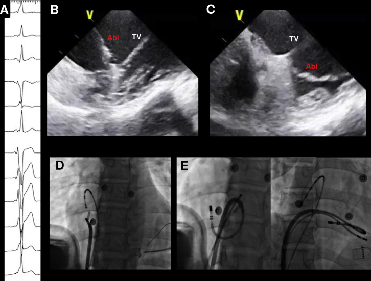
A 65-year-old female patient with Wolff-Parkinson-White syndrome and supraventricular tachycardia was referred after 3 prior failed ablations. The electrocardiogram showed preexcited sinus rhythm with V4 transition, positive delta wave in I, and relatively isoelectric delta wave in inferior leads (Figure 3). An Agilis sheath was used for improved stability and detailed activation mapping was performed during atrial pacing. Earliest ventricular activation was recorded at 9 o’clock in the tricuspid annulus and ICE imaging from the RA identified a small pouch at this location below the TV. Applying a tight curve on the ablation catheter caused the tip to be positioned at this pouch, and good contact force was achieved (18–20 grams). RF was applied, with early elimination of AP conduction. After 1 hour of waiting time, preexcitation did not recur and VA dissociation was observed with ventricular pacing.
Figure 3.
A: Activation map of the right ventricle during atrial pacing showing earliest activation at 9 o’clock on the tricuspid annulus. B: Intracardiac echocardiography imaging of the lateral tricuspid valve (TV), showing a small pouch or recess (red arrow) immediately below the TV. C: Positioning of the catheter inside the pouch, demonstrated by the green mark. D: Left anterior oblique and right anterior oblique views showing the position of the catheter at the successful ablation site. E: Elimination of accessory pathway conduction during ablation.
Case 5
A 31-year-old male patient with Wolff-Parkinson-White syndrome and 4 previous ablation attempts of a right free-wall AP was referred for evaluation. His electrocardiogram showed a delta wave that was positive in leads I and aVL, with precordial transition at V5 (Supplemental Figure 3). Activation mapping during ventricular pacing showed earliest atrial activation at the lateral aspect of the tricuspid annulus (9 o’clock). Using ICE guidance and an Agilis sheath, we positioned the ablation catheter just below the free-wall insertion of the TV on the ventricular aspect. With a tight curve on the catheter, a contact force of 30g could be achieved. RF delivery (30 W) immediately abolished the retrograde AP conduction, which did not recur after a 30-minute waiting period.
Discussion
The TV leaflets represent the main anatomic obstacle when mapping the ventricular aspect of the tricuspid annulus from a transfemoral approach. A subclavian or jugular approach is an alternative when an inferior approach fails, since the catheter can be used as a hook to engage the tricuspid annulus from below.8 However, this has several limitations, including (1) need for an additional vascular access; (2) risk of pneumothorax; (3) higher radiation exposure for the operator; and (4) more challenging manipulation of the ablation catheter from above, with impossibility to simultaneously maneuver the ICE probe.
ICE has been increasingly incorporated into many electrophysiological procedures and may be of particular help for ablation of the TV region. As demonstrated in these cases, ICE is invaluable to confirm the location of the catheter underneath the TV leaflet to ensure proper RF delivery to the myocardial tissue. Usually, this requires steerable sheaths to provide adequate reach and support, and loops on the ablation catheter to place the tip at the subvalvular plane. During ablation, the ICE “homeview” is ideal for monitoring the catheter location along the TV, with gentle clockwise rotation of the ICE probe to visualize the septal aspect of the valve (simultaneous visualization of the aortic root) or counterclockwise rotation to image the lateral annulus.
In the first 3 cases we describe a reproducible technique for ablation of the anterior tricuspid annulus, which involves the aid of a deflectable sheath, a reversed S-curve on the ablation catheter, and the use of ICE to monitor real-time catheter position (Figure 1C, 1D). This method allows direct contact with the tricuspid annulus, avoiding ablation through the TV leaflet, as well as allowing a perpendicular rather than oblique angle of contact. A somewhat equivalent technique has been previously described for ablation of subaortic arrhythmias when a transseptal approach is used.9 The technique we propose involves the following steps:
-
(1)
The ablation catheter is introduced through the Agilis sheath into the RV cavity and the sheath is advanced slightly across the TV with some inferior deflection.
-
(2)
The catheter is then retroflexed using the D-curve, creating a “reversed S-curve” on the whole system. ICE is more useful than fluoroscopy to perform this maneuver, as it allows direct visualization of the RV cavity and prevents pushing against the RV walls or becoming entangled within the valve chordae.
-
(3)
The system is gently pulled back and the curve on the catheter is slowly opened to place the tip of the catheter just between the TV leaflet (anterior or septal) and the ventricular myocardium at the annulus (Figure 2B).
-
(4)
The Agilis curve is adjusted (closed/opened, moved clockwise/counterclockwise) to navigate between the leaflet and the ventricular wall. Contact-force technology is very helpful to quantify the amount of force and to visualize the orientation of the tip using the vector orientation marker.
Interestingly, 3 out of the 5 patients had undergone prior failed ablation attempts using electroanatomic mapping. Also, in some of the cases reported here, early electrograms-to-QRS onset were found, but still the ablation failed with the standard approach. After catheter repositioning under ICE to place the tip between the leaflet and the ventricular myocardium, an even earlier electrogram was found and the ablation was successful, confirming catheter impingement on the leaflet as the most likely cause for failure.
Conclusion
In patients with TV arrhythmias and failed ablation, successful arrhythmia elimination may be achieved by positioning the ablation catheter below the tricuspid annulus, as opposed to the standard approach above the annulus. ICE is essential in these cases to monitor for real-time catheter position.
Footnotes
This research was supported by the Koegel Family Research Fund.
Supplementary data associated with this article can be found in the online version at https://doi.org/10.1016/j.hrcr.2018.02.010.
Appendix. Supplementary data
Supplemental Figure 1.
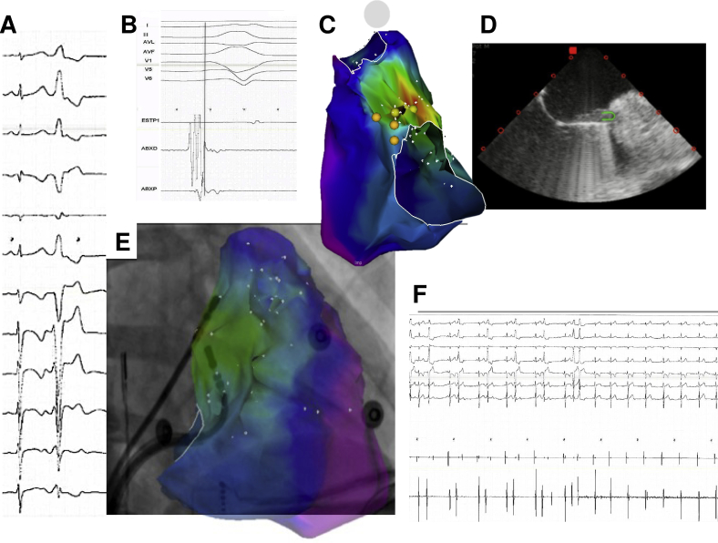
Patient 2. A. Twelve-lead ECG of the clinical PVC. B. Electrogram at site of earliest activation. C. Activation map of the RV showing earliest site in red and His potentials in yellow. D. ICE view obtained with the ICE catheter in the RA. E. Integration of CARTO map and RAO fluoroscopic view, showing the position of the catheter at the time of successful ablation. F. PVC elimination.
Supplemental Figure 2.
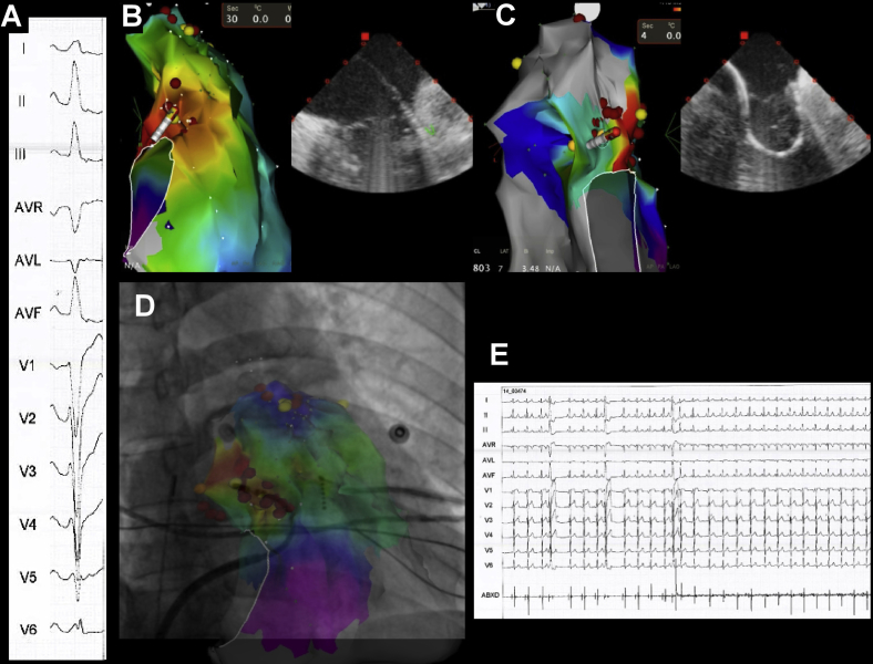
Patient 3. A. Twelve-lead ECG of the clinical PVC. B. Standard approach limited by the presence of the TV leaflets. C. “Reversed S” technique with better reach to the subvalvular tissue. D. Integration of CARTO map and RAO fluoroscopic view, showing the position of the catheter at the time of successful ablation. E. PVC elimination.
Supplemental Figure 3.
Patient 5. A. Baseline ECG showing ventricular preexcitation compatible with right lateral accessory pathway. B, D. Initial failed ablation attempt (ICE visualization and fluoroscopic LAO view). ICE shows the presence of the TV leaflet between the catheter tip and the underlying ventricular myocardium. C, E. By advancing the sheath further into the RV and placing a closed loop on the ablation catheter, the tip is positioned below the TV leaflet, in direct contact with the annulus. Ablation in this spot resulted in successful accessory pathway elimination.
References
- 1.Tada H., Tadokoro K., Ito S. Idiopathic ventricular arrhythmias originating from the tricuspid annulus: prevalence, electrocardiographic characteristics, and results of radiofrequency catheter ablation. Heart Rhythm. 2007;4:7–16. doi: 10.1016/j.hrthm.2006.09.025. [DOI] [PubMed] [Google Scholar]
- 2.Yue-Chun L., Wen-Wu Z., Na-Dan Z., Teng Z., Pin-Xiao W., Bei G., Jia L., Kang-Ting J., Jia-Feng L. Idiopathic premature ventricular contractions and ventricular tachycardias originating from the vicinity of tricuspid annulus: results of radiofrequency catheter ablation in thirty-five patients. BMC Cardiovasc Disord. 2012;12:32. doi: 10.1186/1471-2261-12-32. [DOI] [PMC free article] [PubMed] [Google Scholar]
- 3.Marchlinski F.E., Zado E., Dixit S., Gerstenfeld E., Callans D.J., Hsia H., Lin D., Nayak H., Russo A., Pulliam W. Electroanatomic substrate and outcome of catheter ablative therapy for ventricular tachycardia in setting of right ventricular cardiomyopathy. Circulation. 2004;110:2293–2298. doi: 10.1161/01.CIR.0000145154.02436.90. [DOI] [PubMed] [Google Scholar]
- 4.Silver M.D., Lam J.H., Ranganathan N., Wigle E.D. Morphology of the human tricuspid valve. Circulation. 1971;43:333–348. doi: 10.1161/01.cir.43.3.333. [DOI] [PubMed] [Google Scholar]
- 5.Tornos Mas P., Rodríguez-Palomares J.F., Antunes M.J. Secondary tricuspid valve regurgitation: a forgotten entity. Heart. 2015;101:1840–1848. doi: 10.1136/heartjnl-2014-307252. [DOI] [PMC free article] [PubMed] [Google Scholar]
- 6.Rogers J.H., Bolling S.F. The tricuspid valve: current perspective and evolving management of tricuspid regurgitation. Circulation. 2009;119:2718–2725. doi: 10.1161/CIRCULATIONAHA.108.842773. [DOI] [PubMed] [Google Scholar]
- 7.Anderson R.H., Ho S.Y., Becker A.E. Anatomy of the human atrioventricular junctions revisited. Anat Rec. 2000;260:81–91. doi: 10.1002/1097-0185(20000901)260:1<81::AID-AR90>3.0.CO;2-3. [DOI] [PubMed] [Google Scholar]
- 8.Li T., Zhan X.Z., Xue Y.M., Fang X.H., Liao H.T., Deng H., Wei W., Wu S.L. Combined approach improves the outcomes of catheter ablation of idiopathic ventricular arrhythmias originating from the vicinity of tricuspid annulus. Pacing Clin Electrophysiol. 2014;37:624–629. doi: 10.1111/pace.12341. [DOI] [PubMed] [Google Scholar]
- 9.Ouyang F., Mathew S., Wu S. Ventricular arrhythmias arising from the left ventricular outflow tract below the aortic sinus cusps: mapping and catheter ablation via transseptal approach and electrocardiographic characteristics. Circ Arrhythm Electrophysiol. 2014;7:445–455. doi: 10.1161/CIRCEP.114.001690. [DOI] [PubMed] [Google Scholar]


