Abstract
Commercially available clinical positron emission tomography (PET) detectors employ scintillation crystals that are long (≥20 mm length) and narrow (4–5 mm width) optically coupled on their narrow end to a photosensor. The aspect ratio of this traditional crystal rod configuration and 511 keV photon attenuation properties yield significant variances in scintillation light collection efficiency and transit time to the photodetector, due to variations in the 511 keV photon interaction depth in the crystal. These variances contribute significant to coincidence time resolution degradation. If instead, crystals are coupled to a photosensor on their long side, near-complete light collection efficiency can be achieved, and scintillation photon transit time jitter is reduced. In this work, we compare the achievable coincidence time resolution (CTR) of LGSO:Ce(0.025 mol%) crystals 3–20 mm in length when optically coupled to silicon photomultipliers (SiPMs) on either their short end or long side face. In this “side readout” configuration, a CTR of 102±2 ps FWHM was measured with 2.9×.2.9×20 mm3 crystals coupled to rows of 3×3 mm2 SensL-J SiPMs using leading edge time pickoff and a single timing channel. This is in contrast to a CTR of 137±3 ps FWHM when the same crystals were coupled to single 3×3 mm2 SiPMs on their narrow ends. We further study the statistical limit on CTR using side readout via the Cramér-Rao lower bound (CRLB), with consideration given to ongoing work to further improve photosensor technologies and exploit fast phenomena to ultimately achieve 10 ps FWHM CTR. Potential design aspects of scalable front-end signal processing readout electronics using this side readout configuration are discussed. Altogether, we demonstrate that the side readout configuration offers an immediate solution for 100 ps CTR clinical PET detectors and mitigates factors prohibiting future efforts to achieve 10 ps FWHM CTR.
1. Introduction
The reconstructed image signal-to-noise ratio (SNR) improvement offered from time-of-flight PET (TOF-PET) has spurred considerable efforts to develop PET instrumentation capable of more precisely estimating the interaction time of 511 keV annihilation photons. Current state-of-the-art commercial PET systems have ~315–530 picoseconds (ps) full-width-at-half-maximum (FWHM) timing performance, constraining annihilation events to lie somewhere within a ~5–8 cm region along system detector response lines (LORs) [Jakoby et al. 2011, Miller et al. 2015, Grant et al. 2016, Hsu et al. 2017]. The reconstructed image SNR improvement this localization provides can be estimated according to the relationship between assumed patient diameter (D), the speed of light (c), and the CTR of system (dt) in Equation 1 [Conti 2008].
| (1) |
An important and longstanding milestone for TOF-PET is a system capable of 100 ps FWHM CTR, which would facilitate a 5-fold improvement in image SNR compared to a PET system with no TOF capability, with the potential for transformational impact in count starved and contrast limited clinical scenarios of PET imaging. Ultimately these efforts are geared toward localizing annihilation events along LORs with an accuracy that approaches the resolution limits dictated by positron range, 511 keV photon accolinearity, and detector element width, at about 10 ps FWHM CTR. At this level of performance, an estimated >15-fold improvement in reconstructed image SNR can be realized, or equivalently, effective 511 keV photon sensitivity is boosted by two orders of magnitude.
With advances in SiPM technology and the discovery of novel scintillation materials, sub-100 ps FWHM CTR is now achievable with lutetium based inorganic scintillators [Nemallapudi et al. 2015, Cates et al. 2016, Gundacker et al. 2016a]. However, to date, this timing performance has only been achieved with very short crystal elements (~3–5 mm length). In current commercially-available clinical PET systems, at least 20 mm length lutetium oxyorthosilicate-based crystals are employed to provide adequate detection efficiency for 511 keV photons. For the standard approach of coupling the photosensor to the crystal ends (Figures 1(a) and 1(b)), this increase in crystal length (20 mm vs. 3 mm) significantly reduces and causes variance in light collection efficiency (LCE) at the photosensor and increases the variance in scintillation photon transit time in the crystal, thereby increasing the temporal variance of earliest detected scintillation photons - which are the photons that provide the best estimation of the time of a 511 keV photon interaction. In this standard configuration, the LCE for 20 mm length crystals is reduced to ~40% compared to ~70% for the 3 mm length crystal [Pauwels et al. 2009, Gundacker et al. 2013]. The scintillation photon transit time spread is also increased from tens-of-picoseconds to hundreds-of-picoseconds [Cates et al. 2015]. This light transit time variance is depth-of-interaction (DOI) dependent, including the travel time of the 511keV photon to a specific DOI in the crystal element of interaction. As a result of all these temporal smearing processes and decreased scintillation photon statistics, the CTR performance for 20 mm length crystals for the standard light readout configuration is typically at least 50% worse than that achievable for short crystals. Therefore, for long and narrow elements used in a traditional PET detector design (photosensor coupled to the crystal end), sub-100 ps CTR has not yet been achieved.
Figure 1.
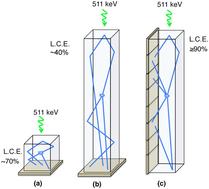
Short and long scintillation crystals with standard light readout at the end of the crystal are shown in (a) and (b). In (c), an alternative scintillation light readout configuration is depicted, where light is readout by a photosensor coupled to the side of the crystal.
1.1. Benefits of Side Readout of Scintillation Crystal Elements
It has previously been shown that coupling high-aspect-ratio (HAR) (i.e. long and narrow) crystal elements to a photosensor on their long side (Figure 1(c)) facilitates near complete LCE, independent of crystal surface finish [Levin 2002]. Another important benefit of this “side readout” configuration is that it reduces the average and variance in the distance scintillation photons must travel to reach the photosensor, thereby reducing the overall scintillation photon transit time jitter. Our group has also shown that this side readout configuration naturally yields a three-dimensional position sensitive detector (3DPSD) capable of positioning one or more interactions per 511 keV photon event, with sub-millimeter positioning accuracy in the depth direction using an energy weighted mean positioning algorithm [Yeom et al. 2015]. This ability to localize 511 keV interactions in 3D mitigates the well known parallax error that leads to radial position dependent spatial resolution within a PET system [Levin 2008]. But note that a 3DPSD is different than a standard depth-of-interaction (DOI) detector [Rafecas et al. 2003, Lerche et al. 2005, Yang et al. 2006, Mosset et al. 2006], which assumes annihilation photons interact only once in the detectors. 3DPSDs enable two important features (1) more accurate positioning of one or more annihilation photon interactions (≥2-interaction inter-crystal scatter events are much more probable than single-interaction photoelectric events, as the scatter fraction for 511 keV photons is roughly double the photoelectric absorption fraction in LSO) [Pratx et al. 2013] and (2) an estimate of the incoming annihilation photon incident angle for ≥2-interaction inter-crystal scatter events, which provides an opportunity to retain a high fraction of 511 keV photon coincidence event types that are normally rejected [Chinn et al. 2006a, Chinn et al. 2006b]. If these normally rejected events can be recovered, and adequate information extracted from them, then the 511 keV photon system sensitivity can be further increased by more than an order of magnitude [Levin 2008, Levin 2012]. Another benefit of a 3DPSD in PET relates directly back to ultra-precise TOF event positioning capabilities. As a system’s achievable CTR moves below 250 ps FWHM, it becomes important to more accurately position the first 511 keV photon interaction location in order to accurately determine the LOR endpoints for more accurately positioning of the TOF-kernel along each LOR during the image reconstruction process [Spanoudaki et al. 2009]. Accurate positioning the TOF kernel along every LOR is an important part of optimizing the benefits from advanced TOF-PET systems.
In summary, coupling photosensors to the long side, as oppose to the short end, of scintillation crystal element facilitates substantially improved LCE, reduced scintillation photon transit time jitter, and intrinsic 3D event positioning. If this side-on scintillation light readout configuration can be translated into a TOF-PET detector in a scalable way, (e.g. one that does not increase the complexity of the detector readout) it is a highly promising detector design to mitigate factors currently affecting the timing performance of PET detectors comprising long and narrow scintillation crystals. This design also enables 511 keV photon sensitivity boosting algorithms via 3D positioning capabilities [Levin 2012]. In this work, we evaluate the achievable CTR with the side readout configuration using an advanced lutetium-based inorganic scintillator and a state-of-the-art analog SiPM technology.
2. Materials and Experimental Methods
2.1. Scintillation Crystals
The scintillation material used in this work was LGSO:Ce(0.05 mol%) (fast-LGSO). This material offers a reduced scintillation decay time compared to LYSO:Ce with similar light output [Loignon-Houle et al. 2017]. Fast-LGSO also exhibits a 10 ps rise time that has been measured with the time correlated single photon counting setup described in [Gundacker et al. 2016b]. Figure 2 shows the measured temporal profile for fast-LGSO [Private Communication, Gundacker 2017]. Two decay time components were found, 37.0 and 11.6 ns, measured with 90.8 and 9.2 % relative intensities. The fitted rise time was 10.3 ps. In [Gundacker et al. 2016b], the importance of a luminescence temporal profile having a fast rise time for scintillation detectors achieving sub-100 ps was presented. This material is therefore a promising candidate material for achieving this level of timing performance. In Section 3, we further explore the potential CTR well below 100 ps. Crystal elements with volumes of 2.9×2.9×3, 2.9×2.9×5, 2.9×2.9×10, and 2.9×2.9×20 mm3 were used in experimental work, and all crystal surfaces were mechanically polished.
Figure 2.
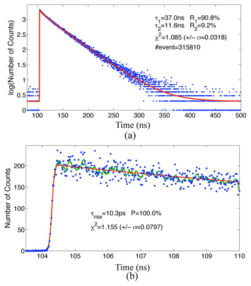
The full temporal luminescence profile for LGSO:Ce(0.05 mol%) (fast-LGSO) is shown in (a), and magnified view of the rising edge of the temporal profile is shown in (b). A two-component decay fit yielded measured 37.2 and 11.8 ns with 90.6 and 9.4% relative intensities, respectively. The measured rise time was 8.9 ps [Gundacker 2017].
2.2. Characterization of Light Output in Side Readout Configuration
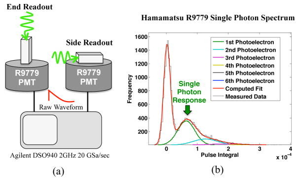
The light output from the scintillation crystals coupled on their short end and long side faces was quantified with a Hamamatsu R9779 photomultiplier (PMT) for the 3, 5, 10, and 20 mm length crystals (Figure 3(a)). This PMT was previously single photoelectron calibrated using the methods outlined in [Bellamy et al. 1994]. Therefore, light output from the crystals was quantified as “number of photons” after correcting for the quantum efficiency of the PMT over the emissions spectrum of fast-LGSO. The single photoelectron response measured from the PMT is shown in Figure 3(b). The anode of the PMT was directly connected to an Agilent DSO940 2GHz oscilloscope and raw waveforms were digitized at 20 Giga-samples per second (GSa/sec). The digitized waveforms were integrated, and the number of photons in each waveform was calculated from the single photoelectron response of the PMT. The light output of the crystals at 511 keV energy deposition was characterized by fitting a Gaussian distribution to the resulting 511 keV photopeak, where the fitted mean was taken as the light output for each crystal. Measurement error was estimated as the square root of the mean number of photons. Note that the quantified light output was not the absolute light yield of the scintillation crystals, rather the number of photons that escape the crystal’s exit face.
Figure 3.
An experimental setup used to quantify light output of fast-LGSO crystals in “end readout” and “side readout” with a Hamamatsu R9779 PMT is shown in (a). In (b), the multi-photoelectron charge spectrum for the PMT used is shown.
2.3. Coincidence Time Resolution Measurements
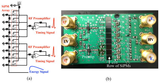
To measure the achievable CTR with crystals coupled to photosensors in the side readout configuration, test boards were designed and assembled for a row of eight 3×3 mm2 SensL-J through-silicon-via (TSV) SiPMs. A schematic of the test boards is shown in Figure 4(a), and a picture of one of the test boards is shown in Figure 4(b). The board was designed such that up to four channels could be connected to a MAR-6 preamplifier [Minicircuits 2017], and two of these preamplifiers could read out all eight SiPMs. The “fast outputs” of the SensL J SiPMs were connected to the preamplifiers, and these outputs served as the timing channels for the test board. The fast output provides a low capacitance path from the SiPM’s Geiger-mode avalanche photodiode cells and therefore offers a high-pass filtered output that mitigates baseline shifts due to dark noise, minimizing the influence of leading edge time pickoff estimation of 511 keV interaction time. If desired, the anodes of the SiPMs may be connected to a resistive mesh with two outputs that optionally provide linear positioning capabilities via the ratio of amplitudes at the output of the two channels, in addition to energy information. Altogether, the test boards were designed with the goal of providing any linear combination of SiPMs to test many possible readout configurations when the sides of scintillation crystals were coupled to the row of SiPMs.
Figure 4.
In (a), a schematic of the circuit designed to test the achievable CTR with the side readout configuration. One of the printed and assembled test boards is shown in (b).
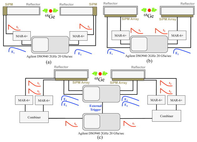
The experimental setups used to measure CTR with end and side readout configuration are shown in Figure 5. CTR for crystal/SiPM pairs oriented in the end readout configuration was measured using SensL-J TSV SiPM evaluation boards with a single 3×3 mm2 SiPM. The fast output of each SiPM was amplified with a Minicircuits MAR-6 preamplifier and passed to an Agilent DSO940 2GHz oscilloscope. Energy signals were taken from the “standard” output (anode) and passed directly to the oscilloscope. Coincidence processing was performed using the acquisition software on the oscilloscope, where the acquisition threshold was placed just below the 511 keV photopeak, and 5000 coincidence events were recorded for the 3, 5, 10, and 20 mm length crystal pairs. Waveforms from both detectors were digitized at 20 GSa/sec. Time pickoff was performed in post processing with leading edge time pickoff. No baseline corrections or advanced digital time pickoff algorithms were used. Coincidence events within the full-width-at-tenth-max of a Gaussian fit to the 511 keV photopeak were considered energy qualified and included in CTR analysis.
Figure 5.
Experimental setups to measure CTR with crystals and SiPMs oriented in end (a) and side (b) readout configuration. Side readout experiments were performed using the test board shown in Figure 4(b), where a row of SiPM pixels were connected together and coupled to the long side of the crystals. An experimental setup used to measure CTR with side readout using depth-of-interaction corrected time stamps is shown in (c).
The same crystals were measured in the side readout configuration using the same experimental setup, depicted in Figure 5(b), using the test boards depicted in Figure 4. The 3, 5, and 10 mm length crystals were coupled on their long side to 1, 2, and 3, SiPMs respectively. Note, the 3 mm length crystals are not really in side readout configuration, as it is essentially a cube, but we also measured CTR with these crystals using the side readout test board using only 1 SiPM active to compare with the measured CTR using the single pixel SensL-J evaluation boards (Figure 5(a)). For the 10 mm length crystal coupled to a row of 3 SiPMs, there was approximately 150 μm of “overhang” at either end 2.9×10 mm2 face.
The 20 mm length crystals were coupled on their sides to a row of six SiPMs in the experimental setup shown in Figure 5(c). This gave an overhang of approximately 250 μm on either end of the 2.9×20mm2 face of the crystal where there was no SiPM. In this setup, the energy and timing outputs of two groups of three SiPMs were shorted together on the test board, yielding two energy channels and two timing channels for each detector. The four energy channels were connected to one oscilloscope and digitized at 20 GSa/sec. Software on this scope was also used to perform coincidence processing. An external trigger output on this scope was connected to a second Agilent DSO940 oscilloscope, where timing channels were digitized at 20 GSa/sec after combining the two timing channels from each detector into a single channel with a Minicircuits ZX10R-14-S+ power combiner. The external trigger of the oscilloscope processing the energy channels was used as an auxiliary trigger for the timing scope. Since these oscilloscopes do not have an external input that serves as a “busy” or “hold-off” trigger, a conservative hold-off time of 500 ms was implemented in software on the energy-measuring oscilloscope, to ensure adequate time for the second (timing) oscilloscope to receive the external coincidence trigger and write the acquired waveforms to the hard drive.
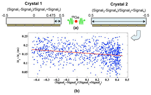
The experimental setup in Figure 5(c) allowed the position of interaction to be estimated via the ratio of the amplitude from the energy channels of the two three-SiPM groups coupled to each 2.9×2.9×20 mm3 crystal. With this information depth-dependent time pickoff correction could be implemented, to investigate its effect on achievable CTR with side readout of 20 mm length crystals. The depth-dependent time pickoff correction is illustrated in Figure 6(a). Interaction depth was calculated as the normalized ratio of signal amplitude from the “front” and “back” SiPM groups. Therefore, interaction depth values ranged from 0.5 to −0.5 (front to back). The depth-dependent time correction was performed by only considering interactions in a very small volume of one crystal (crystal 1) along with interactions within the entire volume of the other crystal (crystal 2). In this way, a simple correction could be implemented by fitting a linear curve to a plot of the time difference between interactions in crystal 1 and crystal 2, as shown in Figure 6(b). The x-axis of Figure 6(b) is the calculated depth-of-interaction, and the y-axis represents the time difference between the two detectors. With these data, a simple correction can be applied to timestamps, like a standard time walk correction. This was repeated in depth-value steps of 0.025, separating crystal 1 into 40 sections. This corresponds to ~0.5 mm steps. However, slight nonlinearity in the calculated depth of interaction exists for events interacting in the very front or back ends of the crystal, since only two channels are used for positioning, and interactions at the extrema of the crystal volume will exhibit less uniformity in light sharing across the two groups of three SiPMs coupled to the 2.9×20 mm2 face of the crystals. Light loss in the regions of overhang at the front and back ends of the crystal can also contribute to nonuniformity in light collection.
Figure 6.
An illustration of the procedure used to make the depth-dependent time walk correction on timestamps for the side readout of 20 mm length crystals. “Signal1” and “Signal2” refer to the energy signals from the anodes of two groups of three SiPMs. Likewise with “Signal3” and “Signal4”.
We also validated the measured CTR with side readout of the 2.9×2.9×20 mm3 crystals using the depth-dependent time pickoff correction. Using the same experimental setup shown in Figure 5(c), the Ge-68 point source was displaced in 2 cm increments for three separate measurements, resulting in an expected shift of 133 ps in the mean of measured CTR distributions (a 2 cm source displacement results in a total change in path length difference of 4 cm for the two 511 keV photons). The source was positioned with an accuracy within 1 mm, and the active portion of the source had a 0.25 mm diameter.
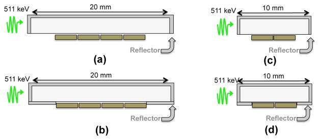
While the ideal case for the side readout configuration would have sensors along the entirety of a long and narrow crystal (see Figures 1(c) and 6(a)), it may also be desired to accomplish an optimal trade off between achievable CTR and active photosensor area, since an increase in photosensor area is also associated with a higher detector readout complexity and cost. To address this, we repeated CTR measurements with 10 and 20 mm length crystals using the crystal/reflector combinations in a “sparse” SiPM readout configuration, shown in Figure 7, and the experimental setup in Figure 5(b). In these measurements, we reduce the photosensitive area coupled to the long sides of the crystals by 30%. In Figures 7(a) and 7(c), the ends of the crystal not connected to SiPMs are left open, and for the configurations shown in Figures 7(b) and 7(d), the same ends of the crystal are covered with one layer of ESR reflector. These two cases were tested to investigate whether the improved light collection from reflector at the end areas of the crystal (where there is no photodetector) would outweigh a potential increase in scintillation photon transit time jitter the reflector might also introduce.
Figure 7.
Illustrations of side readout configurations used to measure the achievable CTR for “sparse” sensor readout. 20 mm length crystals were tested with with four 3×3 mm2 SiPMs in the center of the crystals with (a) and without (b) ESR reflector on the “open” area at the bottom of the crystal. A similar sensor/reflector arrangement was also tested for 10 mm length crystals with two SiPMs ((c) and (d)).
2.4. Analytical CRLB Calculations for Scintillators with Side Readout
The scintillation photon transit time for side readout of crystal elements can be modeled using an analytical model outlined in [Yang et al. 2012 and Cates et al. 2015]. This model can also include the travel time of 511 keV photons to interaction locations (weighted by a material’s linear attenuation coefficient), scintillation luminescence profile, depth-dependent scintillation photon transit time, and temporal response of the photosensor to calculate the Cramér-Rao Lower Bound (CRLB) on CTR via the Fisher statistic [DeGroot 2012], which represents that statistical limit on achievable timing resolution performance for a scintillation detector. The model builds upon a first formalism to analytically calculate this statistic limit on CTR for scintillation detectors [Seifert et al. 2012] by including scintillation light transport for crystal geometries with non-negligible scintillation photon transit time jitter [Cates et al. 2015].
Recently, researchers have also been investigating the potential for improving CTR by exploiting prompt emissions such as hot intra-band luminescence, Cherenkov yield from the primary photoelectron, or other methods that exploit sub-ps optical phenomena [Lecoq et al. 2014, Gundacker et al. 2016b, Dolenec 2013, Kwon et al. 2016, Brunner et al. 2017, Tao et al. 2016, Tao et al. 2017]. The ultimate goal of efforts to develop TOF-PET detectors with the ability to localize 511 keV photon interactions along LORs with an accuracy that approaches the spatial resolution limits dictated by positron range, 511 keV photon accolinearity, and detector element width [Levin et al. 1999]. This would correspond to about 10 ps FWHM CTR. However, improving CTR below 35 ps FWHM would already facilitate localization along the LOR as good as the reconstructed spatial resolution of current commercial systems (~5 mm) and still provide substantial SNR improvement. We calculated the CRLB to investigate potential for improved CTR for a population of prompt photons with a detector having a crystal with 10 ps rise time and optimized light transit time jitter and light collection efficiency in side readout configuration. For LSO and similar scintillation materials, an estimated 15–20 Cherenkov photons are produced for 511 keV photoelectric interactions between wavelengths of 250–600 nm [Lecoq et al. 2010, Brunner et al. 2014]. If ~90% LCE reported in [Levin 2002] for 20 mm length crystals coupled to photosensors on their side is assumed, this provides roughly 10 prompt Cherenkov photons available for detection in the photosensor. In these calculations photosensor PDE and single photon time resolution were parametrically varied.
3. Results
3.1. Light Output for End vs. Side Readout
The measured light output for the 3–20 mm length fast-LGSO crystals coupled to the Hamamatsu R9779 PMT on their narrow ends or long sides is shown in Figure 8(a). For end readout, the measured light output decreases by 37% over the different crystal lengths studied, whereas the mean light output values with side readout differ by less than one percent.
Figure 8.
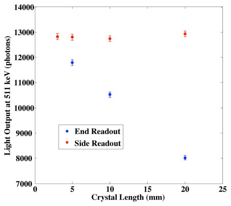
Measured light output at 511 keV energy deposition for fast-LGSO crystals coupled to a Hamamatsu R9779 PMT on their narrow ends or long sides.
3.2. Coincidence Time Resolution Measurements
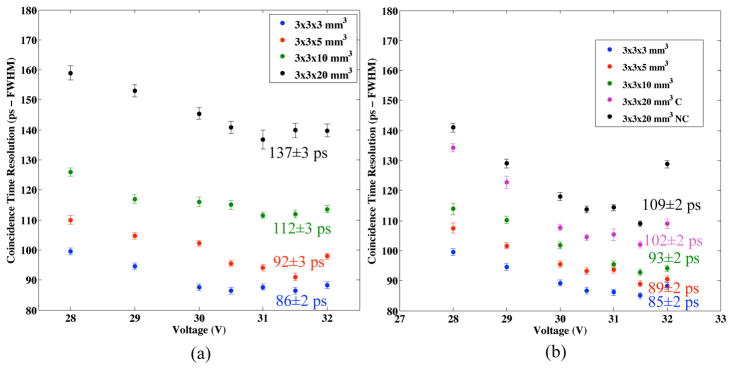
Measured CTR with 3–20 mm length crystals coupled on their narrow ends to a single 3×3 mm2 SiPM is shown in Figure 9(a), and CTR with the same crystals coupled on their long side to a row of SiPMs is shown on Figure 9(b), both as a function of bias voltage. In Figure 9(b), the 3, 5, 10, and 20 mm length crystals were side-coupled to a row of one, two, three, and six 3×3 mm2 SiPMs, respectively. Measured CTR with side readout for the 20 mm length crystals with and without the time walk correction is shown, denoted “NC” for “not corrected” and “C” for “corrected”.
Figure 9.
Measured CTR for fast-LGSO crystals with 3–20 mm lengths in end readout is shown in (a). In (b), the measured CTR with the same crystals using side readout is shown. 20 mm length crystals in side readout are denoted both “NC” for “not corrected” and “C” for “corrected” for the case without and with a time walk correction. Error bars represent a 95% confidence interval on the fit to the CTR distributions.
The magnitude of influence capacitive shaping and cumulative noise had on CTR is shown in Figure 10. CTR measurements with the 2.9×2.9×3 mm3 crystals were repeated using the experimental setup shown in Figure 5(b) with an increasing number of SiPMs (1-to-8) connected in parallel to a single timing channel. In this way, the light collection and transit time jitter remained constant, while the the amount of dark noise and capacitive shaping on the timing channels increased. The black markers in Figure 10 represent measured CTR with one, two, four, and eight SiPMs, with a linear fit shown in red. Also included in this figure are the best CTRs with the 5, 10, and 20 mm length crystals using side readout, being coupled to two, three, and six SiPMs. The best measured CTRs match the linear fit of the 3 mm length crystal measurements with multiple SiPMs within experimental error. Therefore, the effects of multiple SiPMs is the major contributor to degraded CTR with longer crystals. After extracting the contribution to CTR that the increased noise adds from the 5–20 mm length measurements with side readout, the resulting values fall within 85±2 ps, the CTR result achieved with the 3 mm length crystal, within experimental error. Therefore, the same CTR achieved with 3 mm length crystals is achievable with 20 mm length crystals using side readout, when the increased sensor noise is accounted for. This is opposite of the case where crystals are coupled to an SiPM on their narrow end, where increasing crystal length decreases light collection efficiency and significantly increases scintillation photon transit time jitter.
Figure 10.
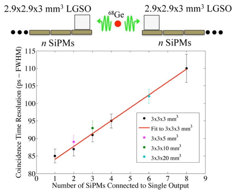
Measured CTR for 2.9×2.9×3 mm3 fast-LGSO crystals is shown as the number of 3×3 mm2 SiPM pixels connected together to a single output was increased (black), with a linear fit to these data (red). Also shown are the best CTR values for 5, 10, and 20 mm length crystals with side readout arranged according to the number of SiPM pixels they were coupled to.
The measured CTR distributions from the validation measurements, where the Ge-68 source was displaced resulting in an expected shift in CTR distributions of 133 ps, are shown in Figure 11. The means of the CTR distributions are correctly displaced, within the experimental error of the measurement. A linear fit to the calculated mean of each CTR distribution yields a slope of 30.6±6.03 cm/ns corresponding to the speed of light, within the experimental error of the linear fit.
Figure 11.
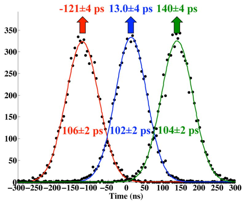
CTR distributions from validation measurements, where a Ge-68 source was displaced by known distances of 2 cm, resulting in an expected shift of CTR distributions of 133 ps.
3.3. Coincidence Time Resolution Measurements with Sparse Sensor Readout
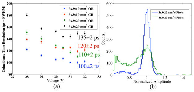
The measured CTRs with sparse sensor readout configurations are shown in Figure 12(a). With two 3×3 mm2 SiPMs centered on the side of 2.9×.2.9×10 mm3 fast-LGSO crystals with and without the remaining area of the side covered in ESR reflector 120±2 and 100±2 ps FWHM were measured, respectively. For the case of a row of four SiPMs centered on the side of 20 mm length crystals with and without ESR reflector on the remaining area of the crystal side, 135±2 and 110±2 ps FWHM were measured respectively. While placing reflector on the open areas of the crystal side coupled to SiPMs improved the 511 keV photopeak amplitude by ~10%, measured CTR was degraded by about 20 ps for the 10 mm length crystals and 25 ps for the 20 mm length crystals.
Figure 12.
Measured CTR for sparse sensor readout configurations with 10 and 20 mm length crystals are shown in (a). The terms “OB” and “CB” are used to denote open and closed bottom, where the portion of the scintillation light exit interface of the crystal not coupled to SiPMs is either left open or covered with ESR reflector. An example of the affect on the 511 keV photopeak with a 20 mm length crystal having sparse sensor readout and OB (green) and one where the bottom is covered by SiPMs.
A disadvantage of leaving the area of the crystal sides not coupled to the SiPMs open was a degraded 511 keV photopeak energy resolution, shown in Figure 12(b). In this figure, the recorded energy spectra for 20 mm length crystals coupled to a row of six SiPMs (blue) is compared to only four SiPMs (green) are compared at an SiPM bias of 31.5V. The lower limit of the x-axis was the acquisition threshold used in CTR measurement. A best fit of a Gaussian curve to the 511 keV photopeak with the 20 mm length crystal coupled to 4 SiPMs yields an energy resolution of 20% (not corrected for saturation). When six SiPMs are coupled to the side of the 20 mm length crystals an energy resolution of 10% was calculated. This broadening of the 511 keV photopeak with four SiPMs and no reflector on the remaining exit surface of the crystals is due to events with interactions that occur near the extremities of the crystal, where a substantial amount of light loss occurs. The 10 mm length crystals with two SiPMs mounted on the side face, and no reflector on the exposed ends exhibited the same behavior.
3.4. Cramér Rao Lower Bound Calculations
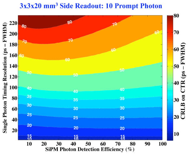
Figure 13 shows the calculated CRLB on FWHM CTR for two 3×3×20 mm3 fast-LGSO crystals coupled to a photosensor on their 3×20 mm2 sides, where 10 Cherenkov photons have been incorporated into the temporal emissions profile used for the calculation in the manner described in [Gundacker et al. 2016b]. The primary factor limiting CTR with this small prompt photon population, having minimal transit time jitter due to crystal side readout, is the photosensor’s SPTR. When 10 prompt photons are available for detection in combination with the scintillation photons in the 10 ps rise time of fast-LGSO, the statistical limit on CTR reaches 35 ps FWHM when the photodetector SPTR is less than 80 ps FWHM, over a wide range of sensor PDE values.
Figure 13.
Calculated CRLB for 3×3×20 mm3 fast-LGSO crystals considered 10 prompt Cherenkov photons, where SPTR and PDE are parametrically varied.
4. Discussion
As demonstrated by earlier work [Levin 2002], measured light output for side readout of long and narrow scintillation crystals is substantially improved compared to the case where a crystal is coupled to a photosensor on its narrow end (Figure 8(a)). For context, consider that in recent years significant effort has been put forth to improve LCE with end-coupled scintillation crystals by exploiting photonic crystal techniques [Knapitsch et al. 2014], and simulated gain in LCE for optimized nanoimprinted structures predict 15–30% improvement compared to a polished exit coupled to a sensor with an optical glue [Knapitsch et al. 2016]. In Section 3.1 we showed that >50% improvement in LCE can already be achieved with the side readout orientation of a 20 mm length crystal, compared to end readout of a crystal with the same length. We also note that scintillation photon transit time jitter before photodetection is reduced in this side readout orientation. In an end readout configuration a large variance exists in scintillation photon transit time due to scintillation photons initially traveling towards or away from the photosensor. Since the average scintillation photon path length to the photodetector is substantially reduced with side readout of cyrstal elements, this variation in scintillation photon transit time is also significantly reduced. The improved LCE and transit time jitter when long crystals are coupled on their side overcomes limitations to CTR imposed on a HAR crystal geometry read out on its narrow end.
The achievable CTR for 3–20 mm length crystals using side readout was shown to differ by <20 ps when a depth-dependent time correction was applied to measurements with 20 mm length crystals (Figure 9(b)). The measured CTRs in Figure 9(b) increase from 86±2 to 102 ±2 ps FWHM as crystal length is increased from 3 to 20 mm length, even though the light output and scintillation photon transit time jitter for these to crystal geometries do not differ significantly, as shown in Figures 8(a) and 8(b). This is expected, since more SiPM pixels are connected to a single channel for timing with the side readout configuration, as the crystal length increases. Connecting the SiPMs in parallel to a single output results in capacitive shaping of the signal that degrades signal rise time and amplitude, which reduces SNR [Bieniosek et al. 2015]. This increase of the total detector capacitance could also potentially influence the single photon time resolution (SPTR) of the device [Acerbi et al. 2014]. A second effect is that the dark noise from the SiPM pixels is all being added into a single channel. As mentioned in Section 2.3, the fast output of the SensL-J SiPMs provides a low capacitance path that minimizes the effects of baseline shifts due to dark noise that can reduce the accuracy and precision of leading edge discrimination for estimation of 511 keV time of interaction. However, as the number of SiPMs tied to a single channel increases, the ability to perfectly compensate for the effects of cumulative dark noise on baseline stability will eventually degrade [Cates et al. 2017]. Data in Figure 10 further clarified that the major contribution to the degraded CTR from 3 to 20 mm length crystals using side readout is effects resulting from multiplexing many SiPMs to a single channel of readout. When the measured CTRs are adjusted for these effects, the same timing performance is calculated for 3–20 mm length crystals, within experimental error.
A sparse sensor readout (i.e. reading out a smaller effective photosensor area) (Figure 7) could potentially mitigate these effects degrading CTR associated with reading out a larger effective photosensor area, but this will come with a trade-off of potentially increased scintillation photon transit time (Figures 7(b), 7(d), and 12(a)) or reduced light collection efficiency (Figures 7(a), 7(c), and 12(b)). Reducing the side area coupled to SiPMs by 30% degraded CTR by <10 ps FWHM. However, the 511 keV photopeak energy resolution was significantly blurred (>20%). In future work, will investigate optimized sparse sensor readout configurations. An implementation of a depth-dependent energy correction may also recover energy response with sparse sensor side readout over “open” regions of the crystal exit surface.
The greatly improved LCE and minimized scintillation photon transit time jitter for side readout of HAR crystals also presents a unique opportunity to exploit a small population of prompt photons. Ongoing efforts to improve the SPTR of SiPMs can facilitate a CTR within a range of a few tens-of-pecoseconds for a wide range of PDE already achieved with state-of-the art SiPM technologies (Figure 13). However, excellent SPTR is required to push the statistical limit to this level, ≤80 ps FWHM. Interestingly, this level of performance has been demonstrated with the Philips DPC 3200 digital SiPM. A timing response of approximately 80 ps FWHM was reported in an experiment where ~5 photons were incident on a pixel of the digital SiPM from a picosecond laser source [Liu et al. 2016]. SPTR at this level has also been reported for 1×1 mm2 FBK NUV SiPMs [Acerbi et al. 2014a]. At the level of SPTR that is currently achieved with single Geiger-mode cells of ~20 ps FWHM [Acerbi et al. 2014b], the statistical limit on CTR is lowered to < 20 ps FWHM. Ongoing development of large area SiPMs with digital readout architectures capable of reading out individual Geiger cells may approach or surpass this level of SPTR in the future, as the number of Geiger-mode cells tied to a single time-to-digital converter can be greatly reduced, minimizing the influence of noise and capacitance on SPTR. It is promising that the side readout detector configuration can potentially offer the photon statistics necessary to achieve ≤ 35 ps FWHM CTR with future technologies that improve the SPTR of analog and digital SiPMs. As [Gundacker et al. 2016b] demonstrated, many hundreds of prompt photons would be required to achieve this level of performance for end-coupled HAR crystal elements ≥10 mm in length, due to larger scintillation photon transit time jitter.
4.1. Potential Scalable Detector Design
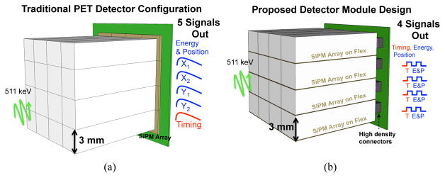
Our proposed detector readout configuration is very different from the conventional PET detector that uses crystal elements coupled on their narrow ends to phototdetectors, with scintillation light sharing between elements and/or charge readout multiplexing of readout channels. Here we discuss some aspects of a scalable detector design having photosensors coupled to the long side of elements in a scintillation crystal array. In Figure 14(a), a detector comprising a 4×4 array of long and narrow crystals, end coupled to a 4×4 array of SiPMs with conventional readout is depicted. This results in four energy and position channels (their sum representing total deposited energy from one or more 511 keV photon interactions), and for TOF capable PET detector designs, typically a dedicated timing channel is used. A detector of equivalent sensitive area with crystals of the same geometry coupled to SiPMs on their long sides is illustrated in Figure 14(b). The conceived detector design would be implemented with edge readout, as outlined in [Levin et al. 2002]. In this configuration, it is important that the dead space between rows of scintillator pixels caused by the photosensors and readout is minimized. This can be accomplished by mounting SiPMs onto thin flexible circuits, where a ex-circuit thickness <100 μm can be used. As an example, the Sensl-J TSV SiPMs used in this work have a total sensor thickness of 640 μm, including the 350 μm glass window, 70 μm silicon, and 220 μm solder ball. Therefore, even with off-the-shelf sensors, a good packing fraction (~74%) can be achieved (Figure 15(a)), so detection efficiency would not be sacrificed much in an edge mounted detector design. This is calculated with an assumed 100 μm reflector around the other faces of the crystals, in addition to the dimensions shown in Figure 15(a) (9/(3.795*3.2)=74%). An improved packing fraction could be realized with a modified SiPM package (Figure 15(b)), where the glass plate between the silicon and crystal is removed, leaving only optical coupling media between the two, and the solder volume used to reflow the sensors to the flexible circuit is reduced. In this proposed assembly (Figure 15(b)), the packing fraction is improved to ~86% (9/(3.255*3.2)=86%), which is within 5–10% of the packing fraction achieved for a conventional commercially-available block detector.
Figure 14.
A traditional PET detector design with an array of long and narrow scintillation crystals coupled end-on to an array of SiPMs is shown in (a). In (b), a proposed detector design employing side readout of the same crystal array, with very thin SiPM devices mounted on a very thin flex circuit.
Figure 15.
End-on view of a row of crystal elements coupled to SiPMs on their side, showing the achievable packing fraction with off-the-shelf version of the sensors used in this work (a) and a greatly improved packing fraction if the optical window could be removed in a future design (b).
Like the traditional detector design in Figure 14(a), the proposed detector employing side readout crystal elements in an array (Figure 14(b)) would multiplex the many energy and timing signals down to just a few channels of readout. This could be accomplished with mixed analog-digital signal processing, similar to what has been presented in [Cates et. al 2017]. In that work, we showed after timestamps have been encoded in a digital pulse, many timing channels can be combined with no degradation in timing performance. The energy and position signals could then be processed through their own multiplexing scheme before being combined with the timing signals to form a single channel of readout for each row of segmented crystals (4 readout channels total in the design depicted in Figure 14(b)). For example, if energy is encoded via time-over-threshold, then each energy pulse could then be given a characteristic delay via an active delay chip, resulting in a digital pulse output represented in Figure 14(b) after being combined with the multiplexed timing signal. Here the leading edge of the first digital pulse encodes time of interaction via leading edge discrimination, the distance between the first and second pulse identifies which crystal the event occured in, and the width of the second pulse identifies deposited energy. In this work, we have presented single-pixel, proof-of-concept measurements with the side readout configuration. There are a lot of important considerations when moving from single pixel measurements to a modular design (ex. minimizing scintillation light crosstalk between crystals in a pixelated array, optimizing the number of channels which can be connected to a leading edge discriminator before multiplexing, etc.). Such aspects of a modular design are under development, and we will report on them in future work.
Comparing this proposed new detector design to the conventional PET detector, it requires no increase/change in crystal volume (the most expensive aspect of a PET detector). It has the same or slightly reduced number of readout channels (e.g. 4 vs. 5) and a similar packing fraction, with a trade off being a moderate increase in photosensor area. With this trade off comes ~100 ps FWHM CTR and 3D positioning capabilities, offering the potential to greatly improve reconstructed image SNR in the manner described in Section 1.1.
5. Conclusions
Coupling photosensors to the long side of scintillation crystal elements, as opposed to their narrow end, offers near complete light collection, substantially reduced scintillation photon transit time jitter, and intrinsic 3D positioning capabilities. A 20 mm length fast-LGSO crystal coupled to a photomultiplier on the long side exhibited the same light output as a 3 mm length crystal coupled on its end. A CTR of 102±2 ps FWHM was measured for two 20 mm length crystals coupled to a row of SensL J TSV SiPMs on their long sides, using a single timing channel and simple leading edge time pickoff. It was further shown that when the effect of increased noise associated with combining multiple SiPMs to a single channel on CTR was accounted for, 20 mm and 3 mm length crystals achieve the same timing performance in the side readout configuration. The number of SiPMs coupled to the side of crystal elements can also optionally be decreased by 30% to reduce cost and complexity of a detector employing the side readout configuration, with a minor degradation in CTR (10–20%). This scintillation light readout strategy offers an immediate solution for 100 ps FWHM CTR clinical TOF-PET detectors with 3DPSD and a pathway for ongoing and future efforts to develop detectors capable of 10 ps FWHM CTR.
Acknowledgments
The authors would like to thank Stefan Gundacker of CERN for measuring the rise and decay time data for fast-LGSO presented in Figure 2. This work was supported in part by the Stanford Molecular Imaging Scholars Program (SMIS) (NIH-NCI R25 CA118681 and 2T32 CA118681-11A1) and R01 CA214669.
References
- Acerbi F, Ferri A, Gola A, Cazzanelli M, Lorenzo P, Zorzi N, Piemonte C. Characterization of single-photon time resolution: from single SPAD to silicon photomultiplier. IEEE Trans Nucl Sci. 2014a;61:2678–2686. [Google Scholar]
- Acerbi F, Cazzanelli M, Ferri A, Gola A, Pavesi L, Zorzi N, Piemonte C. High detection efficiency and time resolution integrated-passive-quenched single-photon avalanche photodiodes. IEEE Jour Selec Top in Quant Elec. 2014b;20:3804608. [Google Scholar]
- Bellamy EH, Bellettini G, Budagov J, Vervelli F, Chirikov-Zorin I, Incagli M, Lucchesi D, Pagliarone C, Tokar S, Zetti F. Absolute calibration and monitoring of a spectrometric channel using a photomultiplier. NIM A. 1994;339:468–476. [Google Scholar]
- Bieniosek MF, Cates JW, Levin CS. Achieving fast timing performance with multiplexed SiPMs. Phys Med Bio. 2016;61:2879–2892. doi: 10.1088/0031-9155/61/7/2879. [DOI] [PubMed] [Google Scholar]
- Brunner SE, Gruber L, Marton J, Suzuki K, Hirtl A. Studies on the Cherenkov effect for improved time resolution of TOF-PET. IEEE Trans Nucl Sci. 2014;61:443–447. [Google Scholar]
- Brunner SE, Schaart DR. BGO as a hybrid scintillator / Cherenkov radiator for cost-effective time-of-flight PET. Phys Med Bio. 2017;62:4421–4439. doi: 10.1088/1361-6560/aa6a49. [DOI] [PubMed] [Google Scholar]
- Cates JW, Vinke R, Levin CS. Analytical calculation of the lower bound on timing resolution for PET scintillation detectors comprised of high-aspect-ratio crystal elements. Phys Med Biol. 2015;60:5141–5161. doi: 10.1088/0031-9155/60/13/5141. [DOI] [PMC free article] [PubMed] [Google Scholar]
- Cates JW, Levin CS. Advances in coincidence time resolution for PET. Phys Med Biol. 2016;61:2255–2265. doi: 10.1088/0031-9155/61/6/2255. [DOI] [PubMed] [Google Scholar]
- Cates JW, Bieniosek MF, Levin CS. Highly multiplexed signal readout for a time-of-flight positron emission tomography detector based on silicon photomultipliers. SPIE Jour Med Img. 2017;4:011012. doi: 10.1117/1.JMI.4.1.011012. [DOI] [PMC free article] [PubMed] [Google Scholar]
- Chinn G, Foudray AMK, Levin CS. Accurate positioning and incorporating large angle tissue scattered photons into PET image reconstruction. IEEE NSS MIC Conf Rec. 2006a:1746–1761. [Google Scholar]
- Chinn G, Foudray AMK, Levin CS. A method to include single photon events in image reconstruction for a 1 mm resolution PET system. IEEE NSS MIC Conf Rec. 2006b:1740–1745. [Google Scholar]
- Conti M. State of the art and challenges of time-of-flight PET. Phys Medi. 2008;25:1–11. doi: 10.1016/j.ejmp.2008.10.001. [DOI] [PubMed] [Google Scholar]
- DeGroot MH. Probability and Statistics. Reading, MA: Addison-Wesley; 2012. pp. 514–22. [Google Scholar]
- Dolenec R. PhD Dissertation. University of Ljubljana; Time-of-flight positron emission tomography using Cherenkov radiation 2013. [Google Scholar]
- Grant AM, Deller TW, Khalighi MM, Maramraju SH, Delso G, Levin CS. NEMA NU 2-2012 performance studies for the SiPM-based ToF-PET component of the GE Signa PET/MR system. Journal of Medical Physics. 2016;43(5):2334–2343. doi: 10.1118/1.4945416. [DOI] [PubMed] [Google Scholar]
- Gundacker S, Knaptisch A, Auffray E, Jarron P, Meyer T, Lecoq P. Time resolution deterioration with increasing crystal length in aTOF-PET system. Nucl Instrum Methods A. 2013;737:92–100. [Google Scholar]
- Gundacker S, Acerbi F, Auffray E, Ferri A, Gola A, Nemallapudi MV, Paternoster G, Piemonte C, Lecoq P. State of the art timing in TOF-PET detectors with LuAG, GAGG, and L(Y)SO scintillators of various sizes coupled to FBK-SiPMs. JINST. 2016a;11:P08008. [Google Scholar]
- Gundacker S, Auffray E, Pauwels K, Lecoq P. Measurement of intrinsic rise times for various L(Y)SO and LuAG scintillators with a general study of prompt photons to achieve 10 ps in TOF-PET. Phys Med Biol. 2016b;61(7):2802–2837. doi: 10.1088/0031-9155/61/7/2802. [DOI] [PubMed] [Google Scholar]
- Hsu DFC, Ilan E, Peterson WT, Uribe J, Lubberink M, Levin CS. Studies of next-generation silicon photomultiplier-based time-of-flight PET/CT system. J Nucl Med. 2017;58(9):1511–1518. doi: 10.2967/jnumed.117.189514. [DOI] [PubMed] [Google Scholar]
- Ito M, Lee JP, Lee JS. Timing performance study of new fast PMTs with LYSO for time-of-flight PET. IEEE Trans Nucl Sci. 2013;60:30–37. [Google Scholar]
- Jakoby BW, Bercier Y, Conti M, Casey ME, Bendriem B, Townsend DW. Physical and clinical performance of the mCT time-of-flight PET/CT scanner. Phys Med Biol. 2011;56:2375–89. doi: 10.1088/0031-9155/56/8/004. [DOI] [PubMed] [Google Scholar]
- Kao CH, Chen CT. Development and evaluation of a dual-head PET system for high-throughput small-animal imaging. NSS/MIC: IEEE Nucl Sci Symp Conf Record. 2003;3:2072–2076. [Google Scholar]
- Knapitsch A, Lecoq P. Review on photonic crystal coatings for scintillators. Int Jour Mod Phys A. 2014;29:1430070. [Google Scholar]
- Knapitsch A, Auffray E, Barbastathis G, Chevalier C, Hsieh CH, Kim JG, Li S, Marshal MSJ, Mazurczyk R, Modrzynski P, Nagarkar V, Papakonstaninou I, Singh B, TA, Lecoqp P. Large scale production of photonic crystals on scintillators. IEEE Trans Nucl Sci. 2016;63:639–643. [Google Scholar]
- Kwon SI, Gola A, Ferri A, Piemonte C, Cherry SR. Bismuth germinate coupled to near ultraviolet silicon photomultipliers for time-of-flight PET. Phys Med Biol. 2016;61:38–47. doi: 10.1088/0031-9155/61/18/L38. [DOI] [PMC free article] [PubMed] [Google Scholar]
- Lecoq P, Auffray E, Brunner S, Hillemanns H, Jarron P, Knapitsch A, Meyer T, Powolny F. Factors influencing time resolution of scintillators and ways to improve them. IEEE Trans Nucl Sci. 2010;47:2411–2416. [Google Scholar]
- Lerche CW, Benlloch JM, Sanchez F. Depth of Gamma-Ray interaction Within Continuous Crystals From the Width of Its Light-Distribution. IEEE Transactions on Nuclear Science. 2005;52:560–572. [Google Scholar]
- Levin CS, Hoffman EJ. Calculation of positron range and its effect on the fundamental limit of positron emission tomography system spatial resolution. Phys Med Biol. 1999;45(2):559. doi: 10.1088/0031-9155/44/3/019. [DOI] [PubMed] [Google Scholar]
- Levin CS. Design of a high-resolution and high-sensitivity scintillation crystal array for PET with nearly complete light collection. IEEE Trans Nucl Sci. 2002;49:2236–43. [Google Scholar]
- Levin CS. New Imaging Technologies to Enhance the Molecular Sensitivity of Positron Emission Tomography. Proceedings of the IEEE. 2008;96:439–467. [Google Scholar]
- Levin CS. Promising new photon detection concepts for high-resolution clinical and preclinical PET. J Nucl Med. 2012;53:167–170. doi: 10.2967/jnumed.110.084343. [DOI] [PMC free article] [PubMed] [Google Scholar]
- Lecoq P, Korzhik M, Vasiliev A. Can transient phenomena help improving time resolution in scintillators. IEEE Trans Nucl Sci. 2014;61:229–234. [Google Scholar]
- Liu S, An S, Li H, Wang C, Ramirez R, Zhang Y, Baghaei H, Wong WH. A Dual-Layer TOF-DOI Detector Block for Whole-Body PET. IEEE Trans Nucl Sci. 2010;59:1805–1808. [Google Scholar]
- Liu Z, Gundacker S, Pizzichemi M, Ghezzi A, Auffray E, Lecoq P, Paganoni M. In-depth study of single photon time resolution for the Philips digital silicon photomultiplier. JINST. 2016;11:P06006. [Google Scholar]
- Loignon-Houle F, Pepin MC, Lecomte R. Scintillation and spectroscopic characteristics of 90%Lu LGSO with variable decay times. IEEE Trans Rad and Plas Med Sci. 2017;1:23–29. [Google Scholar]
- Minicircuits MAR-6 RF Amplifier Data Sheet. 2017 minicircuits.com/pdfs/MAR-6+.pdf.
- Miller M, Zhang J, Binzel K, Griesmer J, Laurence T, Narayanan M, Natarajamani D, Wang S, Knopp M. Characterization of the Vereos digital photon counting PET system. J Nucl Med. 2015;56(3):434. [Google Scholar]
- Mosset JB, Devroede O, Krieguer M Development of an Optimized. LSO/LuYAP Phoswich Detector Head for the Lausanne ClearPET. IEEE Trans Nucl Sci. 2006;53:25–29. [Google Scholar]
- Nemallapudi MV, Gundacker S, Lecoq P, Auffray E, Ferri A, Gola A, Piemonte C. Sub-100 ps coincidence time resolution for positron emission tomography with LSO:Ce codoped with Ca. Phys Med Biol. 2015;60:4635–4649. doi: 10.1088/0031-9155/60/12/4635. [DOI] [PubMed] [Google Scholar]
- Pauwels K, Auffray E, Gundacker S, Knaptisch A, Lecoq P. Effect of aspect ratio on the light output of scintillators. IEEE Trans Nucl Sci. 2009;59:2340–45. [Google Scholar]
- Pepin CM, Bergeron M, Thibaudeau C, Bureau-Oxton C, Shimizu S, Fontaine R, Lecomte R. Digital Identification of Fast Scintillators in Phoswich APD-Based Detectors. IEEE Trans Nucl Sci. 2010;57:1435–1440. [Google Scholar]
- Pratx G, Levin CS. Bayesian reconstruction of photon interaction sequences for high-resolution PET detectors. Phys Med Biol. 2013;54:5073–5094. doi: 10.1088/0031-9155/54/17/001. [DOI] [PMC free article] [PubMed] [Google Scholar]
- Rafecas M, Boening G, Pichler BJ. Intercrystal scatter in a dual-layer, high-resolution LSO-APD positron emission tomography. Physics in Medicine and Biology. 2003;48:821–848. doi: 10.1088/0031-9155/48/7/302. [DOI] [PubMed] [Google Scholar]
- Schmand M, Eriksson L, Casey ME, Andreaco MS, Melcher C, Wienhard K, Flugge G, Nutt R. Performance results of a new DOI detector block for a high resolution PET-LSO research tomograph HRRT. IEEE Trans Nucl Sci. 1998;45:3000–3006. [Google Scholar]
- Spanoudaki VC, Levin CS. Investigating the temporal resolution limits of scintillation detection from pixelated elements: comparison between experiment and simulation. Phys Med. 2011;56:735–756. doi: 10.1088/0031-9155/56/3/013. [DOI] [PubMed] [Google Scholar]
- Seifert S, van Dam HT, Schaart DR. The lower bound on the timing resolution of scintillation detectors. Phys Med Biol. 2012;57:1797–1814. doi: 10.1088/0031-9155/57/7/1797. [DOI] [PubMed] [Google Scholar]
- Tao L, Daghighian HM, Levin CS. A promising new mechanism of ionizing radiation detection for positron emission tomography: modulation of optical properties. Phys Med Biol. 2016;61:7600–7622. doi: 10.1088/0031-9155/61/21/7600. [DOI] [PMC free article] [PubMed] [Google Scholar]
- Tao L, Daghighian HM, Levin CS. Study of material properties important for an optical property modulation-based radiation detection method for positron emission tomography. SPIE J of Medical Imaging. 2017;4(1):011010. doi: 10.1117/1.JMI.4.1.011010. [DOI] [PMC free article] [PubMed] [Google Scholar]
- Yeom JY, Vinke R, Levin CS. Side readout of long scintillation crystal elements with digital SiPM for TOF-DOI PET. Med Phys. 2014;41:122501. doi: 10.1118/1.4901524. [DOI] [PMC free article] [PubMed] [Google Scholar]
- Yang Y, Dokhale PA, Silverman RW. Depth of interaction resolution measurements for a high resolution PET detector using position sensitive avalanche photodiodes. Phys Med. 2006;51:2131–2142. doi: 10.1088/0031-9155/51/9/001. [DOI] [PubMed] [Google Scholar]


