 Volcano plots, which generally describe only thermodynamics, are expanded to include kinetics that markedly influence the performance of homogeneous catalysts.
Abstract
Volcano plots are frequently used as aids in the search for new heterogeneous and electrochemical catalysts. These tools successfully predict catalytic processes based solely on thermodynamic descriptions, which also capably describe many aspects of the catalytic cycles of homogeneous species. However, homogeneous catalysts also frequently depend upon the kinetic influences brought about by steric interactions to promote or prevent specific chemical reactions. Here, a prototypical transformation facilitated by a homogeneous catalysis, the hydroformylation of an olefin using CO and H2, is examined to establish the viability of creating kinetic volcano plots and to determine their ability to ascertain the influences steric bulk plays on catalytic cycle energetics. Similar to their thermodynamic counterparts, kinetic volcanoes successfully reproduce many experimentally known facets of the hydroformylation reaction. In contrast to thermodynamic volcanoes, kinetic volcanoes emphasize changes in the height of the different activation barriers brought about by steric interactions. This crucial information, however, comes with considerable computational cost, since the transition states of catalysts bearing large bulky ligands must be identified and characterized. To overcome this drawback, a procedure is proposed that relates a simple steric parameter, the Tolman cone angle, with the descriptors used to create the kinetic volcano plots. In this way, the activation barriers of bulky catalysts can be estimated without requiring expensive transition state computations. These newly derived structure–activity relationship volcano plots represent useful tools for identifying new homogeneous catalysts.
Introduction
Developing the next generation of catalysts required to undertake the ever-increasing number of desired chemical transformations is a pillar of modern chemical research. While any catalyst that capably completes its required transformation possesses intrinsic value, there is increasing urgency to develop more efficient catalysts based on abundant non-toxic metals that simultaneously minimize environmental impact and maximize economic return. Numerous strategies exist for identifying such an “ideal catalyst” running the gamut from combinatorial-type screening studies to improving the efficiency of a functional catalyst via slight alterations to a ligand environment to better tune stereoelectronics. Outside of the synthetic laboratory, computational assessments of catalytic behaviour are also attractive for a variety of reasons: environmental impacts are negligible, expensive transition metals do not have to be purchased, and, finally, considerable man power is saved because potential catalysts need not be synthesized. Computationally unravelling the reaction mechanisms and analysing the resulting free energy profiles yields critical information regarding rate-limiting steps that ultimately differentiates experimentally viable catalysts from their unviable counterparts. Unfortunately, such detailed mechanistic studies, even when accessed computationally, are neither practical nor time-efficient (Scheme 1, top row). The process becomes untenable for situations requiring the screening of hundreds of catalysts containing myriad metal centres and ligand environments. Moreover, even if this data were available, it would be necessary to examine the free energy profiles individually to extract the most critical information.
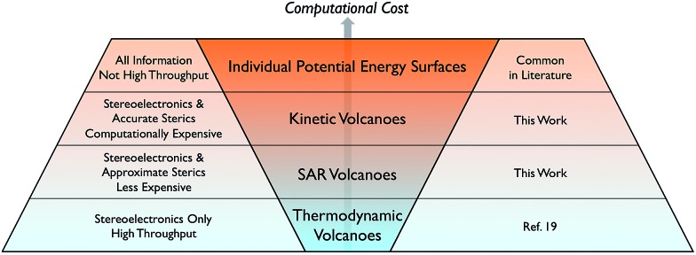
Scheme 1. Current state of methods to computationally assess the thermodynamic and kinetic profiles of homogeneous catalysts.
Faced with challenges of this type, the heterogeneous catalysis and electrochemistry communities developed an intuitive tool, volcano plots, that facilitate the rapid analysis of large data sets with the aim of identifying potential catalysts with appealing thermodynamic profiles. These graphical depictions, named for their abstract resemblance to the geological formation, represent catalytic activity with respect to the magnitude of catalyst/intermediate interactions.1,2 The hallmark volcano shape identifies thermodynamically appealing catalysts, which appear near the top of the plot, and are considered to be “most ideal” because they closely match Sabatier's concept of an ideal catalyst.3 Sabatier's principle states that interactions between a catalyst and a substrate should be neither too weak nor too strong. In other words, placing reactants onto a catalyst and dissociating the resulting products should be equally facile. Deviations from Sabatier's ideal behaviour result in catalysts appearing progressively lower on the volcano plot. In this way, volcano plots allow for the rapid, simultaneous visualization of the key energetic aspects of the catalytic cycle of many catalysts. Indeed, when used as a tool for screening catalysts, volcano plots can be tremendously valuable for experimental/computational collaborations. Data derived from first principles computations serves to narrow the pool of potential catalysts to only those having the best free energy profiles, which can then be tested experimentally. Importantly the behaviour of heterogeneous catalysts has been successfully described using only thermodynamics, a situation that greatly simplifies computational investigations of different potential catalysts since the activation barriers can be ignored. As a result of their ease of use and remarkable ability to assist in rapidly ascertaining data concerning numerous catalysts, volcano plots are now commonplace in the heterogeneous catalysis and electrochemistry literature.4–6
An essential step toward constructing volcano plots is establishing linear free energy scaling relationships (LFESRs)7 that map the properties of different catalytic cycle intermediates onto a single variable (e.g., the binding energy of a single intermediate).8,9 These relationships are based on the notion that the stabilities of the different intermediates depend upon one another and are restricted from varying independently. Thus, if the stability of the single variable descriptor is known, it becomes possible to estimate the stability of all other catalytic cycle intermediates using the corresponding LFESRs. Indeed, the power of such relationships have long been used to better understand physical organic phenomena,10–12 and are still regularly employed to garner information regarding the behaviour of heterogeneous13 and homogeneous14,15 catalysts.
Determining the existence of LFESRs is a relatively straightforward process. Assuming one possesses knowledge of the reaction mechanism for the chemical transformation of interest, key intermediates can be identified from which it is possible to compute (or determine experimentally) the free energy profile for an individual catalyst (Fig. 1a). During the screening process, multiple free energy profiles will be created for catalysts having different metal/ligand combinations. The data from these multiple free energy profiles can then be analysed for the existence of any LFESRs (Fig. 1b). The mathematical equations defining the scaling relationships can then be plotted relative to one another, which leads to a volcano plot (Fig. 1c).16 Individual catalysts are then placed onto the final plot based on the free energies associated with key transformations, thereby identifying species possessing appealing thermodynamic profiles.
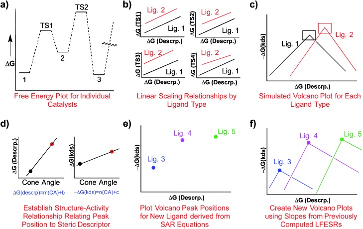
Fig. 1. Overview of the process of creating volcano plots. Free energy plots for individual catalysts are first created (a). After the profiles of multiple catalysts have been determined, linear scaling relationships are determined for key intermediates (b), which relate the stabilities of different species (e.g., reaction intermediates) in terms of a single descriptor. Using the mathematical equations defining the linear scaling relationships a volcano plot can be created (c), which allows facile comparison of the energetics of different catalysts.
While volcano plots are regularly used for identifying potential new catalysts in the heterogeneous and electrochemistry domains,17 applications to homogeneous catalysts are virtually unknown.18 In 2015, we first explored the viability of volcano plots for homogeneous catalysis19 by examining a prototypical example, Suzuki cross-coupling. The resulting homogeneous volcano plots capably reproduced a variety of experimentally known trends and successfully served as a proof-of-principle example that confirmed the earlier abstractly proposed20 framework. Despite this success, our study considered only thermodynamic aspects of the reaction and ignored the important effects that activation barriers have on overall catalytic performance (Scheme 1, bottom row). This point raises a logical question: can the predictive power of volcano plots be increased through the inclusion of kinetic data? It is well established that the success or failure of homogeneous catalysts often lies in the delicate interplay between thermodynamic and kinetic factors. This is particularly true for regio- or enantioselective reactions, where kinetics fundamentally alter the final isomer ratio. The purpose of this contribution is to explore the viability of constructing “kinetic volcanoes” (Scheme 1, 2nd and 3rd rows) and interpreting the resulting data by examining the hydroformylation of an alkene as a prototypical kinetically driven reaction.
 |
1 |
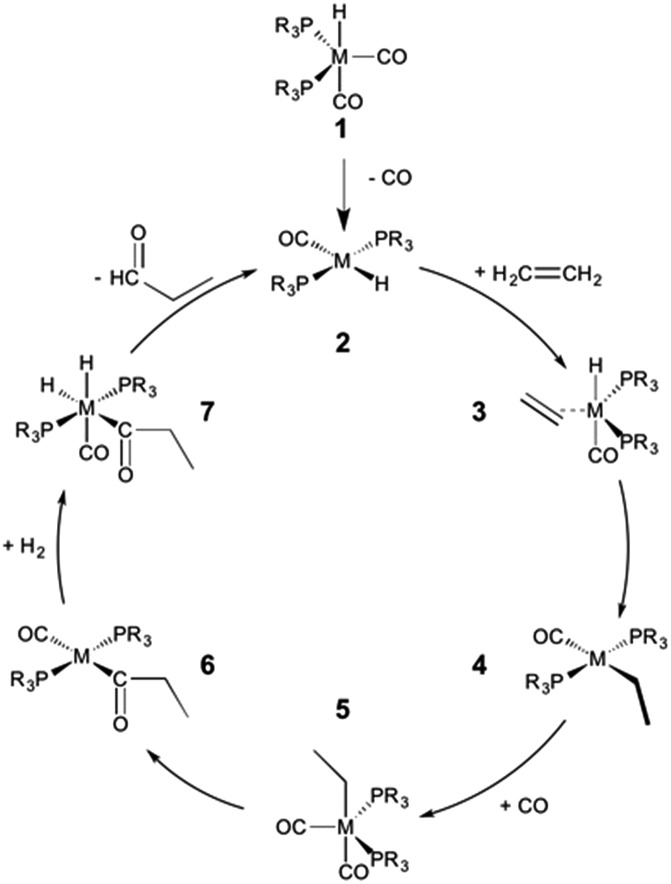
The hydroformylation of alkenes via the addition of CO and H2 (eqn (1)) is an industrially important reaction21–27 that employs transition metal containing homogeneous catalysts. While the earliest transformations relied upon Co catalysts,28 Wilkinson's 1965 discovery29,30 of a Rh-based alternative that utilized milder conditions paved the way for the patented low-pressure oxo process of Union-Carbide, which today is used to produce enormous quantities of different aldehydes. To varying degrees this reaction can also be catalysed by other metals,31 but Rh is the most active.21 The proposed reaction mechanism for Rh-catalysed hydroformylation is depicted in Fig. 2. CO dissociation from 1 yields 2 and serves as the entry point into the catalytic cycle. From 2 olefin coordination leads to the π-complex 3, which rearranges to the σ-complex 4. Addition of CO yields 5 and then 6 following CO insertion into the metal–carbon bond. The addition of H2 then produces 7, which undergoes reductive elimination to give 2, completing the catalytic cycle. For the purposes of this study, ethene was selected as the olefin. This choice is motivated by two factors: first, using ethene eliminates conformational problems that arise from using longer alkenes, second, due to the equivalent nature of the carbon atoms, the hydroformylation of ethene results in only one product (propanal), thereby removing competing pathways that lead to the linear and branched regioisomers for asymmetric alkenes. While issues of regioselectivity are certainly of interest, for the purposes of this proof-of-principle study we chose to minimize the occurrence of such complicating factors and focus on assessing the viability and value of creating kinetic volcano plots.
Fig. 2. Mechanism for the Rh-catalyzed hydroformylation of an olefin. M = Rh, R = Ph.
Since the goal of this work is to probe the ways in which different metal/ligand combinations influence the thermodynamic and kinetic aspects of olefin hydroformylation through the use of density functional theory computations, we examined group 8 (Fe, Ru, Os), 9 (Co, Rh, Ir), and 10 (Ni, Pt)32 metals coupled with a series of monodentate phosphine ligands of varying sizes (PH3, PMe3, PPh3, PCy3). The different metal/ligand combinations produced 32 catalysts, from which linear free energy scaling relationships were built and, ultimately, volcano plots representing both the thermodynamics and kinetics constructed. For the sake of simplicity and to more closely follow the Fig. 2 mechanism, the oxidation states of the catalysts were adjusted to comply with the known 16e–/18e– nature of the reaction mechanism. Thus, each of the group 8 and 10 catalysts was represented as a charged system, isoelectronic with the group 9 metal.
Computational details
The geometries of all species were optimized using the M06 (ref. 33 and 34) density functional in conjunction with the def2-SVP35 basis set in implicit benzene solvent using the SMD solvation model36 in Gaussian 09.37 The nature of each stationary point was confirmed by analysis of vibrational frequencies (zero imaginary frequencies for minima, one for transition states).38 To remove known problems with the size of the integration grid with the Minnesota family of density functionals39 the “Ultrafine” grid was uniformly employed for optimizations and frequency computations. To complement the M06 free energies, single-point computations on the optimized M06 geometries were undertaken using a density-dependent dispersion correction40–43 appended to the PBE0 (ref. 44 and 45) functional (PBE0-dDsC) with the triple-ζ Slater type orbital TZ2P basis set as implemented in ADF.46,47 Reported PBE0-dDsC free energies include solvation corrections from COSMO-RS48 (determined at the PBE0-dDsC/TZ2P theoretical level), also as implemented in ADF. Note that the free energies as determined by both PBE0-dDsC and M06 correlated well with one another (see ESI, Fig. S7†).
Results and discussion
Linear free energy scaling relationships
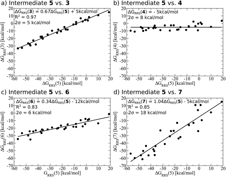
Demonstrating the existence of the linear free energy scaling relationships (LFESRs) is the first step in creating volcano plots. Establishing these relationships permits the description of the relative free energy of each catalytic cycle intermediate [ΔGRRS, the binding free energy relative to the reference state, which is taken as the first point in the catalytic cycle, 2] in terms of the stability of a chosen descriptor intermediate [here ΔGRRS(5) is used as the descriptor]. Accordingly, eqn (2)–(6) define the ΔGRRS for intermediates 3–7. By making use of the ΔGRRS values for our set of catalysts,49 LFESRs begin to emerge, as shown in Fig. 3.50 As a result of these clear relationships, the thermodynamics of the catalytic cycle (e.g., the relative stabilities of all intermediates) can be cast entirely in terms of ΔGRRS(5).
 |
2 |
 |
3 |
 |
4 |
 |
5 |
 |
6 |
Fig. 3. Linear free energy scaling relationships amongst intermediates for the thermodynamic steps of olefin hydroformylation without consideration of different ligand size. The free energies are relative to a reference state, defined in eqn (2)–(6). The mathematical equations that define the linear scaling relationships are used to create the simulated reaction profile and, ultimately, the final volcano plot (vide infra). The zero slope observed between intermediates 5 and 4 indicates that the binding energy is independent of the choice of catalyst.
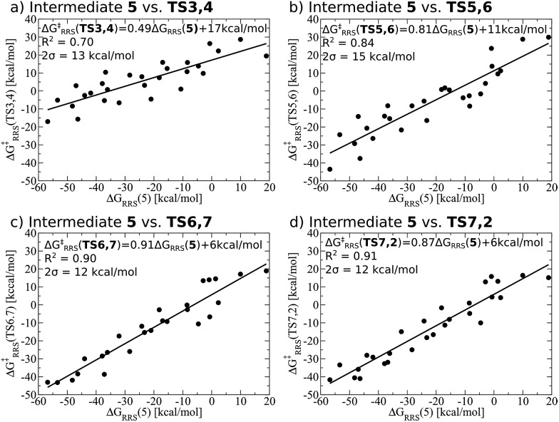
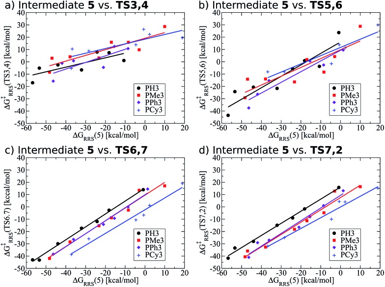
While linear free energy scaling relationships ably describe the thermodynamic interplay amongst intermediates for some homogeneous catalytic cycles, the existence of similar relationships that delineate kinetic aspects is less clear. Certainly amongst the most celebrated works along this line is the Bell–Evans–Polanyi (BEP) model11,12 that describe linear relationships between activation energies and a descriptor, thereby permitting determination of kinetic parameters. For instance, BEP relationships are useful in describing some organic reactions51,52 and have shed light on processes occurring in heterogeneous catalysis.53,54 On the other hand, these relationships have shortcomings of their own, including problems describing certain aspects of organometallic complexes.55 Thus, it is necessary to determine if kinetic aspects of the hydroformylation catalytic cycle, namely the free energy needed to overcome the activation barriers between intermediates, correlate with a purely thermodynamic descriptor (e.g., ΔGRRS of an intermediate). Fortunately, Fig. 4 shows that correlations do exist between the thermodynamic descriptor, ΔGRRS(5), and the relative free energies associated with each of the transition states (TS3,4, TS5,6, TS6,7, TS7,2). Owing to this fact, it is possible to construct volcano plots that describe aspects of both reaction thermodynamics and kinetics, which will be shown in the proceeding section.
Fig. 4. Linear free energy scaling relationships amongst intermediates for the kinetic steps of olefin hydroformylation without consideration of different ligand size. The mathematical equations that define the linear scaling relationships are used to create the simulated reaction profile and, ultimately, the final volcano plot (vide infra).
Constructing and interpreting volcano plots
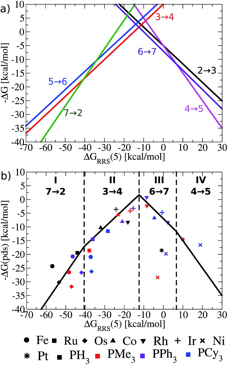
Having established the existence of linear free energy scaling relationships (LFESRs), volcano plots capable of identifying both thermodynamically and kinetically attractive catalysts can be created. Volcano plots illustrate the relationship between the free energies needed to move between catalytic cycle intermediates, ΔGRxn (e.g., ΔG7→2), which appear on the y-axis and the chosen descriptor, indicative of the relative stability of an intermediate [for our purposes, ΔGRRS(5), as defined by eqn (4)], which appears on the x-axis. The lines describing the reaction energy of moving between any two intermediates in the catalytic cycle are obtained from the earlier derived LFESRs (see ESI for a detailed explanation†).56 Plotting each of these relationships together gives Fig. 5a, which is a complete overview of catalytic cycle thermodynamics for hydroformylation. This plot is tremendously informative; if the descriptor value [ΔGRRS(5)] for any catalyst is known then the reaction energy of any step in the catalytic cycle, as derived from the LFESRs, can be estimated directly from the relationships plotted in Fig. 5a.
Fig. 5. (a) Overview of thermodynamics of olefin hydroformylation without consideration of ligand size, as derived from the linear free energy scaling relationships that define the catalytic cycle depicted in Fig. 2. (b) Volcano plot illustrating the thermodynamic suitability of catalysts derived from (a). Reactions that define the potential determining step are: 7 → 2 for region I, 3 → 4 for region II, 6 → 7 for region III, and 4 → 5 for region IV. Lines defining the volcano are obtained by taking the lowest –ΔG(pds) value amongst all the reaction for each ΔGRRS(5) value. Note that the deviations of the points representing individual catalysts from the free energies predicted through linear scaling relationships (depicted as lines) are expected and acceptable. Significant deviations from the scaling relationships [such as seen in Ni(PMe3)2 and Ni(PPh3)2] may be indicative of unusual behaviour by a specific catalyst.
Extracting the most relevant information from Fig. 5a leads to the volcano plot shown in Fig. 5b in which only the relationships for the most difficult reaction step to complete, the potential determining step, are depicted. The potential determining step is ascertained from eqn (7).
| ΔG(pds) = max[ΔGRxn(2 → 3), ΔGRxn(3 → 4), ΔGRxn(4 → 5), ΔGRxn(5 → 6), ΔGRxn(6 → 7), ΔGRxn(7 → 2)] | 7 |
Put more simply, eqn (7) states that the reaction between catalytic cycle intermediates having the most negative –ΔG(pds) value (y-axis) for any descriptor value (x-axis) represents the potential determining step. Thus, the nature of the potential determining step directly relates to how strongly a catalyst binds a substrate [i.e., the x-axis value, ΔGRRS(5) delineates which ΔGRxn is the most energetically difficult]. When the catalyst binds substrates very strongly [i.e., very exergonic binding energies for ΔGRRS(5)] the reaction moving between 7 → 2 is potential determining (green line). If a catalyst still overbinds substrates, but to a lesser extent then 3 → 4 is potential determining (red line). When a catalyst weakly underbinds substrates 6 → 7 is potential determining (purple line) and when substrates are strongly underbound 4 → 5 is potential determining (pink line). These reactions divide the Fig. 5b volcano plot into four regions (I–IV), which correspond to two unique situations. The two regions located to the left of the volcano peak (I and II), are commonly known as the volcano's “strong binding” slope. As their name implies, catalysts in this region bind substrates too strongly. Thus, the release of the final product (7 → 2) or hydrogen atom release by the metal associated with moving from a π- to a σ-complex (3 → 4) are thermodynamically difficult and serve as potential determining steps. Conversely, the right slope (regions III and IV), commonly referred to as “weak binding”, characterizes situations where the substrates bind too weakly to the metal centre. Catalysts falling in those regions have problems completing mechanistic steps requiring the addition of new ligands, including H2 (6 → 7) and CO (4 → 5) coordination.
Once the slopes of the volcano plot representing the potential determining steps have been identified, visualizing the points representing catalysts only involves plotting Cartesian coordinates [ΔGRRS(5), –ΔG(pds)] obtained from the previously computed free energy profiles.57 Examining the placements of the individual catalysts in Fig. 5b already confirms known experimental trends, even from this solely thermodynamic picture. For example, Rh catalysts (indicated by “[blacktriangledown]” in Fig. 5b) appear near the volcano peak, a placement corresponding to a thermodynamic free energy plot for these catalysts in which all steps are exergonic or roughly thermoneutral, including the potential determining step.58 Indeed, the energetic assessments indicated in Fig. 5b align well with the experimentally established enhanced activity of Rh-based catalysts. Other catalyst appearing high on the volcano, such as those containing Ir (+) and Co (▲) metals likewise show good thermodynamic free energy profiles, which echoes their experimental capabilities.59–61 Note that all of the group 9 metals tend to cluster around the top of the volcano, indicating that catalysts incorporating these metals are more ideal in terms of Sabatier's principle, as the intermediates are neither bound too strongly nor too weakly.
While group 9 metals closely follow Sabatier's principle and, thus, appear high on the volcano plot, metals belonging to groups 8 and 10 uniformly appear in the lower regions. The placement of catalysts into these regions means the free energies required to move between catalytic cycle intermediates are energetically uneven (i.e., a combination of more highly endergonic and exergonic steps) for these species.54 Correspondingly, the potential determining step is more energetically costly and these catalysts have overall less favourable thermodynamics. Group 8 metals uniformly appear on the strong binding (left) side of the volcano, meaning that reducing the number of coordinated ligands, such as releasing products, is energetically very costly. Steps of this nature are particularly problematic for Fe and Os, with Ru appearing to suffer less. This slight shift of Ru-catalysts toward the volcano peak corroborates their known uses for hydroformylation,31,62,63 while Fe (ref. 64) and Os (ref. 65–67) are less commonly employed. Group 10 metals suffer from the opposing problem of their group 8 counterparts: rather then binding intermediates too strongly; adding the necessary intermediates (H2 and CO) to complete the catalytic process is energetically costly. As a result, group 10 metals uniformly appear on the weak binding (right) side of the volcano plot. Indeed, Ni,68 Pd,69,70 and Pt (ref. 71) are all capable of catalysing hydroformylation reactions, but generally require co-catalysts72,73 or proceed through alternative mechanisms than that studied here.31
While the influence of the metal centre is quite clear, the effect of ligand size is more difficult to discern. In general, adding bulkier ligands destabilizes the intermediates, which is seen by a shift to weaker binding (i.e., a left to right movement on the volcano plot as steric bulk is increased). From a purely thermodynamic perspective, group 8 catalysts appearing on the strong-binding side of the volcano (left side) will benefit from larger ligands, since bulkier ligands destabilize the intermediates (causing a rightward shift on the volcano plots) that would push these species closer to the volcano peak and, correspondingly, reduce the endergonicity of the potential determining step. On the other hand, group 10 metals already bind too weakly. Further destabilization of the intermediates via the inclusion of bulkier ligands would only exacerbate the problem, leading to even less favourable thermodynamic energy profiles (i.e., more endergonic free energies for the potential determining step).
Looking at the influences of ligand size for particular metal species also reveals key pieces of information regarding how volcano plots can best be used for screening new catalysts. For Rh, the two intermediate-sized ligands (PMe3 and PPh3) have better thermodynamics than the smallest (PH3) and bulkiest (PCy3) ligands, while for Ir and Co, thermodynamic factors appear less influenced by ligand bulk, as the potential determining steps for each species are predicted to be roughly equivalent. Of course, the lack of any discernable trends regarding ligand choice is unsurprising, given that differences in ligand bulkiness should minimally influence thermodynamic aspects of the catalytic cycle for the case studied here. However, some aspects of ligand bulkiness, particularly when favourable non-bonded interactions involving large ligands are used to promote reactions or form specific products,74–78 as is known to occur in organocatalysis,79,80 may be observed in thermodynamic assessments of catalytic behaviour. Fortunately, checking the behaviour of bulkier catalysts from a thermodynamic perspective can be accomplished relatively easily, since only minima on the potential energy surface need to be computed. By plotting the LFESRs for a series of catalysts containing a combination of ligands with greater and lesser amounts of steric bulk any steric factors that arise in the thermodynamics would quickly be visible as outlier points in the LFESRs.
Importantly, the generally small impact of ligand bulk indicates that in future studies aiming to better understand the thermodynamics of different catalysts, smaller, less bulky ligands should be used (e.g., PMe3 to represent phosphines, OMe2 to represent ethers, etc.) since their bulkier alternatives often give similar thermodynamic profiles but require considerably more computational time to obtain. However, the same situation should not be observed in kinetic volcanoes, which should show significant influences that arise from ligand bulk. To determine if this is true, we turn toward constructing kinetic volcano plots to analyse the different catalysts.
Kinetic volcano plots
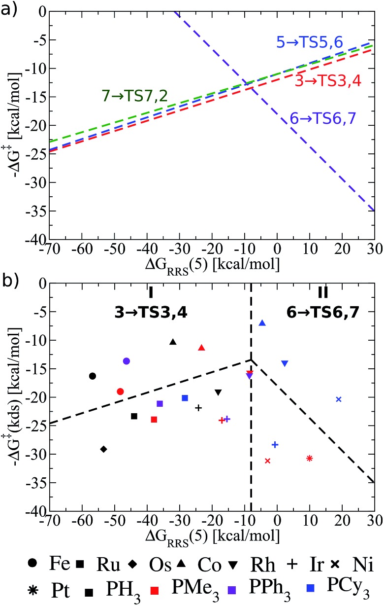
Thermodynamic volcano plots, like those just discussed, assume a “best case” scenario of a catalyst's free energy profile that distinguishes potentially “good” from “poor” species. Of course, thermodynamically “good” catalysts may still be hindered by unfavourable kinetic situations, in which case a thermodynamically less active catalyst may ultimately prove more active. Given this lack of a comprehensive picture, we turn our attention toward creating kinetic volcano plots to determine their ability to provide additional information. The process of creating the kinetic volcano shown in Fig. 6b parallels that described earlier. Some minor differences exist however; specifically, the y-axis is now defined as the kinetic determining step (kds), given by eqn (8).
| ΔG‡(kds) = max[ΔG‡(3 → TS3,4), ΔG‡(5 → TS5,6), ΔG‡(6 → TS6,7), ΔG‡(7 → TS7,2) | 8 |
Fig. 6. (a) Overview of the olefin hydroformylation kinetics without considering ligand size, as derived from the linear free energy scaling relationships that define the catalytic cycle depicted in Fig. 2. (b) Volcano plot illustrating the kinetic suitability of different catalysts derived from (a). Reactions that define the kinetic determining step are 3 → TS3,4 for region I and 6 → TS6,7 for region II. Lines defining the volcano are obtained by taking the lowest –ΔG‡(kds) value amongst all the reaction for each ΔGRRS(5) value.
As can be seen in the comprehensive kinetic overview provided in Fig. 6a, the LFESRs defining the free energies of 3 → TS3,4, 5 → TS5,6, and 7 → TS7,2 run parallel to one another and are also very close energetically. This means that the barriers to overcome the transition states associated with converting the olefin from a π-bound to a σ-bonded alkyl group (3 → TS3,4), inserting CO into the metal–alkyl bond (5 → TS5,6), and inserting an H atom into the metal C O bond (7 → TS7,2), are roughly equivalent. Since the largest reaction barriers are associated with moving from 3 to TS3,4 (i.e., it is the lowest line on the left slope of Fig. 6a), this reaction step is used to define the kinetic determining step for region I in Fig. 6b.81 Indeed, this matches the strong-binding nature of the left side of the volcano plot, since moving from 3 to 4viaTS3,4 should be influenced by how strongly the metal centre binds the H atom. Likewise, 6 → TS6,7 defines the slope of the kinetic volcano in region II (Fig. 6b), which aligns with the weak binding nature of the H2 addition that characterizes moving from 6 to 7viaTS6,7. Using these newly created volcano plots, it is possible to assess the different catalytic systems based on a kinetic picture and to compare and contrast trends predicted by thermodynamic and kinetic pictures.
Many of the same trends identified in the thermodynamic volcano (Fig. 5b) are also seen in its kinetic counterpart (Fig. 6b). For instance, group 9 metals tend to lie higher on the volcano than those of group 8 and 10. The peaks of both the kinetic and thermodynamic volcanoes each indicate the ideal strength of the catalyst/substrate interaction (x-axis) is the same [i.e., ΔGRRS(5) value of ∼–10 kcal mol–1]. Therefore, individual catalysts appear in the same areas of both volcano plots (i.e., group 8 – strong binding, group 10 – weak binding). However, the relative energetic ordering of the metals has changed: thermodynamically Rh-based species had the best energetic profile, yet catalysts containing Co centres appear slightly better when kinetics are considered (i.e., they lie higher on the volcano plot). As an example, the kinetic determining step for RhPCy3 (6 → TS6,7) has a barrier height for the potential determining step that is ∼8 kcal mol–1 higher than the CoPCy3 species. Ir-based catalysts show less appealing kinetic profiles and uniformly appear in the lower regions of the kinetic volcano.
Disappointingly, the effects of ligand bulkiness are only somewhat clear from the kinetic volcano. For Co and Rh the bulkiest ligand (PCy3) have a more favourable kinetic determining step than for less bulky ligands, despite being shifted away from the top of the volcano. Indeed, this trend is relatively robust, also appearing for Ru (group 8) and Ni (group 10), but not for Ir, which shows an opposing trend. Of course, using LFESRs that combine the energetic descriptions of the kinetic aspects of all phosphine ligands without consideration of their size may lead to a somewhat muddled picture, in which the influences of ligand bulk cannot be properly ascertained. Considering the LFESRs and volcano plots in a different way may unravel the effects that sterically bulky ligands play on reaction kinetics, thus, it is necessary to take a closer look at these relationships.
Kinetic linear free energy scaling relationships and volcano plots revisited
Previously, we presented linear free energy scaling relationships (LFESRs) between intermediates assuming that all variations in metal/ligand environment could be combined into a single relationship. While the correlations obtained using this assumption were satisfactory (see R2 and 2σ values, Fig. 4), the lack of clear trends associated with ligand bulkiness warrants a closer examination of the LFESRs used to construct the kinetic volcano plot. To achieve this, we derived new LFESRs separately for each ligand type, as shown in Fig. 7. While the relationships between ΔG‡RRS(TS3,4) and ΔG‡RRS(TS5,6) with ΔGRRS(5) appear to be independent of ligand bulk (Fig. 7a and b), those associated with both TS6,7 and TS7,2 are strongly affected. Both Fig. 7c and d show unambiguous downward shifts of the linear scaling relationships with increasing steric bulk. Thus, the ligand-specific LFESRs clearly show that catalytic cycle kinetics are influenced by ligand size. Because of the differences in the LFESRs defining different ligands, constructing kinetic volcanoes representing each ligand type may reveal more detailed information about the role sterics play in the free energy profiles of different catalysts.
Fig. 7. Revised linear free energy scaling relationships amongst intermediates for the kinetic steps of olefin hydroformylation separated by ligand type.
Also note that these newly derived relationships benefit from greatly improved correlations [higher R2 values and smaller standard deviations (2σ), see ESI Fig. S2†] that arise when the ligands are classified individually. Because of this, volcano plots created from ligand-specific LFESRs will provide a more accurate description of the catalytic cycle. The importance of this point cannot be understated, as having LFESRs capable of accurately predicting the relative free energies of catalytic cycle intermediates and transition states for catalysts with unknown free energy profiles is paramount for the rapid, yet accurate, screening of new catalysts. Having distinguished that different ligand sizes produce distinct LFESRs, we now construct ligand-specific kinetic volcano plots.
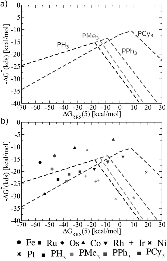
Fig. 8 shows these new ligand-specific kinetic volcanoes, which appear dramatically different from one another. Notably, the height of each volcano increases moving from the least to the most bulky ligand. This situation illustrates that the barrier height of the kinetic determining step decreases when bulkier ligands are used. While the shifts are rather minor amongst PH3, PMe3, and PPh3, the change is vivid for the bulkiest PCy3 ligand, corresponding to a transition state barrier of around 12 kcal mol–1, as opposed to 18 kcal mol–1 for the smaller PH3 ligand. Importantly, this finding shows that increasing the bulkiness of the phosphine ligand results in a more appealing catalysts, which is only identified when examining kinetic aspects of the catalytic cycle. Fig. 8b illustrates that the location of actual catalysts on the volcano plots closely correspond to the predicted energies based on LFESRs, indicating that kinetic volcanoes would also be useful for predicting new catalysts. Having established that both general thermodynamic volcano plots and ligand-specific kinetic volcano plots identify two important yet distinct aspects of the catalytic cycle energetics, we proceed to demonstrate how these type of plots can be used to identify and predict the behaviour of new catalysts.
Fig. 8. (a) Overview of the hydroformylation kinetics separated by ligand type, as derived from the linear free energy scaling relationships that define the catalytic cycle depicted in Fig. 2. (b) Volcano plot illustrating the kinetic suitability of catalysts derived from (a).
Screening for new catalysts using general thermodynamic and ligand-specific kinetic volcanoes
The ability of both general thermodynamic and ligand-specific kinetic volcano plots to distinguish different aspects of catalytic cycle energetics makes them unique tools for identifying new catalysts. This process begins by computing the thermodynamic profiles of a selected number of catalysts possessing various (non-bulky) ligands with differing stereoelectronic properties and metal centres. The actual number of catalysts required will vary for each specific application, with the key criterion being the establishment of reliable linear free energy scaling relationships (LFESRs) that permit the energetics of the catalytic cycle to be estimated by computing a single descriptor variable, as shown earlier (vide supra). Thermodynamic volcano plots can then be created, which will identify one or more metal/ligand combinations possessing appealing thermodynamic profiles. With the thermodynamic volcanoes (created from only a handful of ligand/metal combinations) in hand, the thermodynamics of any number of other catalysts can be rapidly assessed solely by computing the value of the descriptor variable [in our case ΔGRRS(5)], which provides an estimate of the free energy needed to complete the potential determining step.55 In many cases, this information will be sufficient to move to the experimental laboratory and synthesize those catalysts identified through the screening study to fully uncover their activity.
While thermodynamic studies will often provide the necessary amount of data to move directly to the laboratory, it can be envisioned that in some instances more information regarding the role steric interactions play in dictating activation barrier heights will be desired. In these cases it becomes necessary to construct kinetic volcano plots. While we have already shown that kinetic volcanoes distinguish subtle aspects related to catalytic cycle energetics and reproduce known experimental trends, their principle drawback is their considerable computational cost. As such, an ideal and cheap tool for screening homogeneous catalysts would facilitate access to the same type of information obtained from kinetic volcano plots but without the need to undertake the time-intensive task of computing all the necessary data for numerous catalysts.
One attractive solution to more quickly access kinetic data would be establishing a structure–activity relationship (SAR) between a parameter capable of describing ligand sterics (e.g., Tolman's cone angle,82 Verloop's Sterimol,83etc.) and the descriptor used to create the kinetic volcano plot. Indeed, chemists often use steric parameters to better understand, describe, and even predict different aspects of homogeneous catalysis.77,84–88 A hypothetical procedure to create kinetic volcanoes based on structure–activity relationships (SAR volcanoes) is outlined in Fig. 9. First, the free energy profiles of a series of catalysts bearing the same ligand must be computed (Fig. 9a). The number of individual catalysts tested bearing this specific ligand need only be sufficient to establish reliable linear free energy scaling relationships (LFESRs) in the manner previously outlined (Fig. 9b, black lines). This procedure needs to be completed for several small to medium sized ligands (absolute minimum of two but including more should give more accurate predictions, vide infra), which leads to different sets of LFESRs for each ligand type (Fig. 9b, red versus black lines). Using these ligand-dependent LFESRs hypothetical volcanoes for each ligand can be created following the earlier described procedures (Fig. 9c). Each ligand-specific volcano has a different peak point (black and red squares, Fig. 9c). Additionally, each ligand type has a specific steric descriptor, such as the Tolman cone angle. Using the peak point from each ligand-specific volcano along with the ligand-specific steric descriptor, a mathematical relationship can be established that relates the Cartesian coordinates of the peak position [in our case representative of ΔGRRS(5) and –ΔG‡(kds)] to the steric parameter (in our case the Tolman cone angle), as seen in Fig. 9d. The steric parameters for other ligands, for which no data has been computed, can easily be obtained from a database or determined as needed. By combining the steric parameter values of these untested ligands with the mathematical relationships relating the peak position coordinates to the steric parameters the new peak location for the hypothetical volcano of any ligand can be established (Fig. 9e). Finally, the same slopes obtained from the volcano plots of computed ligands can be used as approximations to construct a hypothetical SAR kinetic volcano (Fig. 9f).
Fig. 9. Summary of the procedure used to create structure–activity relationship (SAR) volcanoes from previously computed linear scaling relationships and volcano plots. First, the free energy profiles for several catalysts bearing the same ligand are computed, panel a. Afterwards linear scaling relationships are established that describe the relationship between relative free energies of the transition states and the free energy of the descriptor variable, panel b. This procedure is repeated a minimum of two times. Simulated volcano plots for each ligand type are then derived from the linear scaling relationships, panel c. The peak positions (x and y coordinates) are then related to a steric parameter, such as the cone angle, and equations are derived that relate the steric parameter to a new peak position, panel d. The peak positions of the hypothetical volcanoes for new catalysts can then be plotted, panel e, using the previously derived mathematical relationships. The final hypothetical volcanoes can then be created by using the volcano slopes from the computed data, panel f.
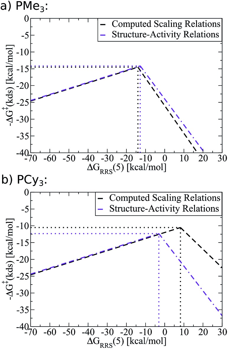
As an example of the procedure to create SAR kinetic volcanoes, the LFESRs for the PH3 and PPh3 ligands were obtained by computing the free energy profiles (including transition states) of just eight catalysts [Fe, Ru, Os, Co, Rh, Ir, Fe, Pt] for each ligand type. The resulting LFESRs describing those ligands are depicted in Fig. 7 (PH3: black lines, PPh3: purple lines). Using only those LFESRs, the corresponding volcano plots can be created, which appear in Fig. 8a (PH3: black, PPh3: purple). Cartesian coordinates defining the peak positions [i.e., ΔGRRS(5) and –ΔG‡(kds)] of each of the Fig. 8a simulated kinetic volcanoes can then be related to the Tolman cone angle using a linear fit (analogous to Fig. 9d). Knowing the Tolman cone angle for other phosphine ligands (e.g., see database in ref. 82), the peak points for the new ligand-specific kinetic volcano plots can be derived. As a final step, the sides of the volcanoes can be approximated by using the slopes from computed volcanoes of ligands with the closest Tolman cone angle (for this example, slopes from either PH3 or PPh3). Following this procedure produces the SAR kinetic volcanoes for the PMe3 and PCy3 ligands shown in purple in Fig. 10. As can be seen, the agreement between the black volcanoes, which were derived directly from the computed data for the PMe3 and PCy3 ligands, and their estimated counterparts is quite satisfactory. While some deterioration is seen for the largest ligand, particularly in the prediction of the x-coordinate, the projected value of kinetic determining steps (y-axis) differ only slightly. Despite the observed reduction in accuracy, it should be stressed that these estimations were obtained with a considerable reduction of computational time since no data for either the PMe3 or the PCy3 ligands was needed to derive the purple Fig. 10 plots.
Fig. 10. Comparison of computed kinetic volcano plots with volcano plots derived from structure–activity relationships associated with the Tolman cone angle. Black lines represent computed data derived from linear free energy scaling relationships (LFESRs) while purple lines represent predictions made from structure–activity relationships.
To demonstrate the full power of the above-described methodology, we created SAR kinetic volcanoes for several phosphine ligands for which we computed no data (purple lines, Fig. 11). The three representative ligands include one having very little bulk, P(OMe)3, one extremely bulky, P(Mes)3, and one of intermediary bulk, P(NMe2)3. Using these SAR volcanoes, the predicted kinetic determining step for any catalyst bearing a phosphine ligand can be estimated solely by computing the descriptor value [ΔGRRS(5)]. Such a tool is remarkably appealing, as the approximate value of the highest activation barrier encountered in the catalytic cycle for any ligand can be quickly identified. Thus, accessing the kinetic information of synthetically appealing catalysts identified from thermodynamic volcanoes can be accomplished with very little computational expense.
Fig. 11. Structure–activity relationships (SAR) volcanoes for selected phosphine ligands computed using structure–activity relationships fit from four (green) and two (purple) data points.
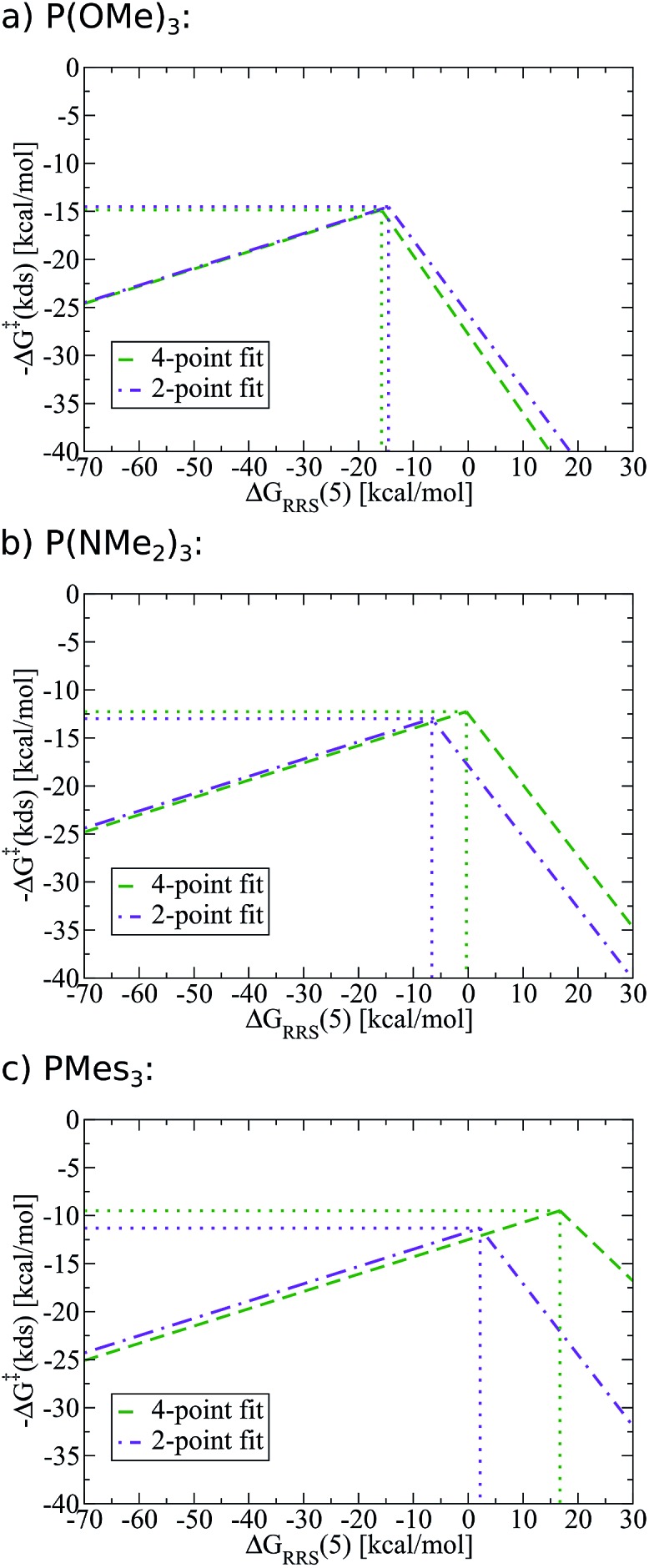
One potential strategy for improving the accuracy of predictions made from SAR volcanoes is including additional ligands into the fitting procedure (e.g., complete the Fig. 9a–d steps with more ligand types). Indeed, using a 4-point (green lines, Fig. 11), as opposed to the earlier employed 2-point fit (purple lines, Fig. 11), changes the peak location of the volcano that corresponds to the free energy associated with the kinetic determining step (y-axis) and the ideal descriptor value (x-axis). The quality of the estimates are less affected for P(OMe)3, while more significant deviations exist for P(Mes)3. It must again be stressed, however, that the improvements made by using a fit from more ligand points come at a significant increase in computational time. Users are encouraged to undertake studies that maximize the predictive ability of SAR kinetic volcanoes while simultaneously minimizing computational expense.
Scope and limitations of the method
While the use of thermodynamic, kinetic, and SAR volcano plots across all types of metal catalysed reactions would represent the broadest possible use of the tools and methods described here, there are currently some limitations. Namely, the use of volcano plots requires a priori knowledge of the most important facets of the reaction mechanism. Moreover, the mechanism must be sufficiently robust that it remains essentially unaltered when different catalysts containing a variety of ligand and metal types are used. While one of our future objectives is creating a tool able to describe multiple mechanistic pathways, in their current state we envision homogeneous volcano plots as being broadly applicable to analyse industrially important reactions that proceed through well-understood catalytic cycles, such as hydrogenation, hydroformylation, and olefin polymerization.
Conclusions
In this work we established the viability of creating volcano plots capable of describing catalytic cycle kinetics for a prototypical reaction from homogeneous catalysis. These kinetic volcanoes, akin to their thermodynamic counterparts, succeed in reproducing experimentally established trends. However, in contrast to thermodynamic volcanoes, kinetic volcanoes have the added ability to distinguish the influences that ligand steric bulk plays on the height of activation barriers. Having established the ability of kinetic volcano plots to reproduce known experimental findings, we created a tool that allows access to the kinetic influences brought about by different phosphine ligands without the considerable computational effort necessary to obtain linear free energy scaling relationships for the bulkiest ligands. The Tolman cone angle, which measures the bulkiness of phosphine ligands using a single numeric parameter, correlated well with the descriptors that define the kinetic volcanoes. Using the relationships between the ligand sterics and the volcano descriptor resulted in the establishment of structure–activity relationship (SAR) volcano plots. The procedures described within permit access to the estimated kinetic data of any size ligand that can be derived by computing only a handful of reaction profiles for catalysts bearing small ligands. As a result, the tools developed here, along with those that have been previously established (see overview in Scheme 1), should ably serve in the screening of new homogeneous catalysts for numerous chemical transformations. In particular, it would be highly appealing to use these newly developed tools to screen new catalysts for their regio-/enantioselective activities.
Supplementary Material
Acknowledgments
The National Center of Competence in Research (NCCR) “Materials' Revolution: Computational Design and Discovery of Novel Materials (MARVEL)” of the Swiss National Science Foundation (SNSF) and the EPFL are acknowledged for financial support. Dr Ganna Gryn'ova, Prof. Kay Severin, and Prof. Xile Hu are acknowledged for helpful discussion and critical reading of the manuscript.
Footnotes
†Electronic supplementary information (ESI) available: Details on deriving the linear scaling relationships, creating the volcano plots, and building the structure–activity relationships volcano plots, as well as computed values of the catalytic cycles using the PBE0-dDsC and M06 functionals are included. Cartesian coordinates of relevant compounds are included (.xyz). See DOI: 10.1039/c6sc01660j
References
- Gerischer H. Bull. Soc. Chim. Belg. 1958;67:506–527. [Google Scholar]
- Parsons R. Trans. Faraday Soc. 1958;54:1053–1063. [Google Scholar]
- Sabatier P., La Catalyse en Chimie Organique, Librarie Polytechnique, Paris, 1913. [Google Scholar]
- Nørskov J. K., Bligaard T., Rossmeisl J., Christensen C. H. Nat. Chem. 2009;1:37–46. doi: 10.1038/nchem.121. [DOI] [PubMed] [Google Scholar]
- Dau H., Limberg C., Reier T., Risch M., Roggan S., Strasser P. ChemCatChem. 2010;2:724–761. [Google Scholar]
- Greeley J., Markovic N. M. Energy Environ. Sci. 2012;5:9246–9256. [Google Scholar]
- Man I. C., Su H.-Y., Calle-Vallejo F., Hansen H. A., Martínez J. I., Inoglu N. G., Kitchin J., Jaramillo T. F., Nørskov J. K., Rossmeisl J. ChemCatChem. 2011;3:1159–1165. [Google Scholar]
- Abild-Pedersen F., Greeley J., Studt F., Rossmeisl J., Munter T. R., Moses P. G., Skúlason E., Bligaard T., Nørskov J. K. Phys. Rev. Lett. 2007;99:016105. doi: 10.1103/PhysRevLett.99.016105. [DOI] [PubMed] [Google Scholar]
- Calle-Vallejo F., Martínez J. I., García-Lastra J. M., Rossmeisl J., Koper M. T. M. Phys. Rev. Lett. 2012;108:116103. doi: 10.1103/PhysRevLett.108.116103. [DOI] [PubMed] [Google Scholar]
- Hammett L. P. J. Am. Chem. Soc. 1937;59:96–103. [Google Scholar]
- Bell R. P. Proc. R. Soc. London, Ser. A. 1936;154:414–429. [Google Scholar]
- Evans D. J., Polanyi M. Trans. Faraday Soc. 1938;34:11–24. [Google Scholar]
- Calle-Vallejo F., Loffreda D., Koper M. T. M., Sautet P. Nat. Chem. 2015;7:403–410. doi: 10.1038/nchem.2226. [DOI] [PubMed] [Google Scholar]
- Audran G., Brémond P., Marque S. R. A., Siri D., Santelli M. Tetrahedron. 2014;70:2272–2279. [Google Scholar]
- Wang Y., Montoya J. H., Tsai C., Ahlquist M. S. G., Nørskov J. K., Studt F. Catal. Lett. 2016;146:304–308. [Google Scholar]
- For a more detailed description of creating volcano plots from linear free energy relationships see ref. 19
- For a recent example see: Lehtimäki M., Hoffmannová H., Boytsova O., Bastl Z., Busch M., Halck N. B., Rossmeisl J., Krtil P., Electrochim. Acta, 2016, 191 , 452 –461 . [Google Scholar]
- A noteworthy exception is the work of Morris and co-workers, who used volcano plots to examine the activity of a catalytic system with respect to both steric and electronic parameters of phosphorus ligands. See: Sues P. E., Lough A. J., Morris R. H., Organometallics, 2011, 30 , 4418 –4431 . [Google Scholar]
- Busch M., Wodrich M. D., Corminboeuf C. Chem. Sci. 2015;6:6754–6761. doi: 10.1039/c5sc02910d. [DOI] [PMC free article] [PubMed] [Google Scholar]
- Swiegers G. F., Mechanical Catalysis: Methods of Enzymatic, Homogeneous, and Heterogeneous Catalysis, John Wiley & Sons, Hoboken, NJ, 2008. [Google Scholar]
- Wiese K.-D. and Obst D., in Catalytic Carbonylation Reactions, ed. M. Beller, Springer, Berlin, 2010, pp. 1–33. [Google Scholar]
- Weissermel K. and Arpe H.-J., in Industrial Organic Chemistry, Wiley-VCH, Weinheim, 2008, pp. 127–144. [Google Scholar]
- Breit B., Seiche W. Synthesis. 2001:1–36. [Google Scholar]
- Breit B., in Metal Catalyzed Reductive C–C Bond Formation, ed. M. Krische, Springer, Berlin, 2007, pp.pp. 139–172139–172. [Google Scholar]
- Casey C. P. and Hartwig J. F., in Organotransition Metal Chemistry: From Bonding to Catalysis, ed. J. F. Hartwig, University Science Books, Sausalitos, 2010, pp. 751–769. [Google Scholar]
- Franke R., Selent D., Börner A. Chem. Rev. 2012;112:5675–5732. doi: 10.1021/cr3001803. [DOI] [PubMed] [Google Scholar]
- van Leeuwen P. W. N. M., Homogeneous Catalysis - Understanding the Art, Kluwer Academic Publisher, Dodrecht, 2004. [Google Scholar]
- Heck R. F., Breslow D. S. J. Am. Chem. Soc. 1961;83:4023–4027. [Google Scholar]
- Osborn J. A., Wilkinson G., Young J. F. Chem. Commun. 1965:17. [Google Scholar]
- Evans D., Osborn J. A., Wilkinson G. J. Chem. Soc. A. 1968:3133–3142. [Google Scholar]
- Pospech J., Fleischer I., Franke R., Buchholz S., Beller M. Angew. Chem., Int. Ed. 2013;52:2852–2872. doi: 10.1002/anie.201208330. [DOI] [PubMed] [Google Scholar]
- The location of stationary points of catalysts with Pd centers was attempted, however, locating stable structures for these species proved to be quite difficult. As a result, Pd based catalysts are not included in this study
- Zhao Y., Truhlar D. G. Acc. Chem. Res. 2008;41:157–167. doi: 10.1021/ar700111a. [DOI] [PubMed] [Google Scholar]
- Zhao Y., Truhlar D. G. Theor. Chem. Acc. 2008;120:215–241. [Google Scholar]
- Weigend F., Ahlrichs R. Phys. Chem. Chem. Phys. 2005;7:3297–3305. doi: 10.1039/b508541a. [DOI] [PubMed] [Google Scholar]
- Marenich A. V., Cramer C. J., Truhlar D. G. J. Phys. Chem. B. 2009;113:4775–4777. doi: 10.1021/jp809094y. [DOI] [PubMed] [Google Scholar]
- Frisch M. J., Trucks G. W., Schlegel H. B., Scuseria G. E., Robb M. A., Cheeseman J. R., Scalmani G., Barone V., Mennucci B., Petersson G. A., Nakatsuji H., Caricato M., Li X., Hratchian H. P., Izmaylov A. F., Bloino J., Zheng G., Sonnenberg J. L., Hada M., Ehara M., Toyota K., Fukuda R., Hasegawa J., Ishida M., Nakajima T., Honda Y., Kitao O., Nakai H., Vreven T., Montgomery J., Peralta J. E., Ogliaro F., Bearpark M., Heyd J. J., Brothers E., Kudin K. N., Staroverov V. N., Kobayashi R., Normand J., Raghavachari K., Rendell A., Burant J. C., Iyengar S. S., Tomasi J., Cossi M., Rega N., Millam M. J., Klene M., Knox J. E., Cross J. B., Bakken V., Adamo C., Jaramillo J., Gomperts R., Stratmann R. E., Yazyev O., Austin A. J., Cammi R., Pomelli C., Ochterski J. W., Martin R. L., Morokuma K., Zakrzewski V. G., Voth G. A., Salvador P., Dannenberg J. J., Dapprich S., Daniels A. D., Farkas O., Foresman J. B., Ortiz J. V., Cioslowski J. and Fox D. J., Gaussian, Inc., Wallingford, CT, 2009.
- Several minima for different catalytic cycle intermediates were found to contain one imaginary frequency with a very small value (e.g. <20 cm–1) that we were unable to remove. For the purposes of this paper, these species were still classified as minima
- Wheeler S. E., Houk K. N. J. Chem. Theory Comput. 2010;6:395–404. doi: 10.1021/ct900639j. [DOI] [PMC free article] [PubMed] [Google Scholar]
- Steinmann S. N., Corminboeuf C. J. Chem. Theory Comput. 2010;6:1990–2001. doi: 10.1021/ct1001494. [DOI] [PubMed] [Google Scholar]
- Steinmann S. N., Corminboeuf C. Chimia. 2011;65:240–244. doi: 10.2533/chimia.2011.240. [DOI] [PubMed] [Google Scholar]
- Steinmann S. N., Corminboeuf C. J. Chem. Phys. 2011;134:044117. doi: 10.1063/1.3545985. [DOI] [PubMed] [Google Scholar]
- Steinmann S. N., Corminboeuf C. J. Chem. Theory Comput. 2011;7:3567–3577. doi: 10.1021/ct200602x. [DOI] [PubMed] [Google Scholar]
- Perdew J. P., Burke K., Ernzerhof M. Phys. Rev. Lett. 1996;77:3865–3868. doi: 10.1103/PhysRevLett.77.3865. [DOI] [PubMed] [Google Scholar]
- Adamo C., Barone V. J. Chem. Phys. 1999;110:6158–6170. [Google Scholar]
- Fonseca Guerra C., Snijders J. G., te Velde G., Baerends E. J. Theor. Chem. Acc. 1998;99:391–403. [Google Scholar]
- te Velde G., Bickelhaupt F. M., van Gisbergen S. J. A., Fonseca Guerra C., Baerends E. J., Snijders J. G., Ziegler T. J. Comput. Chem. 2001;22:931–967. [Google Scholar]
- Klamt A. WIREs Computational Molecular Science. 2011;1:699–709. [Google Scholar]
- 32 catalysts were used in this study. However, this number could be significantly reduced provided that good linear scaling relationships exist with fewer number of species
- Through the examination of multiple possibilities, ΔGRRS(5) was found to be the best descriptor, as it correlated well with the ΔGRRS of other intermediates. Also note that in contrast to our previous study (ref. 19), the slopes of scaling relationships were allowed to vary freely rather than to rely on expected changes in bond order. This resulted in a significant reduction of the standard deviations for the LFESRs
- Zhong G., Chan B., Radom L. J. Am. Chem. Soc. 2007;129:924–933. doi: 10.1021/ja066251a. [DOI] [PubMed] [Google Scholar]
- Lai C.-H., Li E. Y., Chen K.-Y., Chow T. J., Chou P.-T. J. Chem. Theory Comput. 2006;2:1078–1084. [Google Scholar]
- Nørskov J. K., Bligaard T., Logadottir A., Bahn S., Hansen L. B., Bollinger M., Bengaard H., Hammer B., Sljivancanin Z., Mavrikakis M., Xu Y., Dahl S., Jacobsen C. J. H. J. Catal. 2002;209:275–278. [Google Scholar]
- Vojvodic A., Calle-Vallejo F., Guo W., Wang S., Toftelund A., Studt F., Martínez J. I., Shen J., Man I. C., Rossmeisl J., Bligaard T., Nørskov J. K., Abild-Pedersen F. J. Chem. Phys. 2011;134:244509. doi: 10.1063/1.3602323. [DOI] [PubMed] [Google Scholar]
- Usharani D., Lacy D. C., Borovik A. S., Shaik S. J. Am. Chem. Soc. 2013;135:17090–17104. doi: 10.1021/ja408073m. [DOI] [PMC free article] [PubMed] [Google Scholar]
- For a detailed description of how the hypothetical volcano plot is constructed, see the ESI of this manuscript and that of ref. 19
- See ref. 19 for a full description of how individual catalysts are placed onto a volcano plot
- The phenomenon of the "ideal" free energy profile has been discussed previously. For example, see Fig. 2 of ref. 19 and the accompanying discussion for more details
- Hebrard F., Kalck P. Chem. Rev. 2009;109:4272–4282. doi: 10.1021/cr8002533. [DOI] [PubMed] [Google Scholar]
- Wu X.-F., Fang X., Wu L., Jackstell R., Neumann H., Beller M. Acc. Chem. Res. 2014;47:1041–1053. doi: 10.1021/ar400222k. [DOI] [PubMed] [Google Scholar]
- Piras I., Jennerjahn R., Jackstell R., Spannenberg A., Franke R., Beller M. Angew. Chem., Int. Ed. 2010;50:280–284. doi: 10.1002/anie.201001972. [DOI] [PubMed] [Google Scholar]
- Evans D., Osborn J. A., Jardine F. H., Wilkinson G. Nature. 1965;208:1203–1204. [Google Scholar]
- Sanchez-Delgado R. A., Bradley J. S., Wilkinson G. J. Chem. Soc., Dalton Trans. 1976:399–404. [Google Scholar]
- Reppe W., Vetter H. Justus Liebigs Ann. Chem. 1953;582:133–161. [Google Scholar]
- Sánchez-Delgado R. A., Andriollo A., Valencia N. J. Chem. Soc., Chem. Commun. 1983:444–445. [Google Scholar]
- Marrakchi H., Nguini Effa J.-B., Haimeur M., Lieto J., Aune J.-P. J. Mol. Catal. 1985;30:101–109. [Google Scholar]
- Wu L., Liu Q., Spannenberg A., Jackstell R., Beller M. Chem. Commun. 2015;51:3080–3082. doi: 10.1039/c4cc05626d. [DOI] [PubMed] [Google Scholar]
- Tang C., Zeng Y., Cao P., Yang X., Wang G. Catal. Lett. 2009;129:189–193. [Google Scholar]
- Drent E., Budzelaar P. H. M. J. Organomet. Chem. 2000;593–594:211–225. [Google Scholar]
- Konya D., Almeida Leñero K. Q., Drent E. Organometallics. 2006;25:3166–3174. [Google Scholar]
- Scrivanti A., Berton A. J. Organomet. Chem. 1986;314:369–383. [Google Scholar]
- Kehoe L. J., Schell R. A. J. Org. Chem. 1970;35:2846–2848. [Google Scholar]
- Ruegg H. J., Pregosin P. S. J. Organomet. Chem. 1986;316:233–241. [Google Scholar]
- Knowles R. R., Jacobsen E. N. Proc. Natl. Acad. Sci. U. S. A. 2010;107:20678–20685. doi: 10.1073/pnas.1006402107. [DOI] [PMC free article] [PubMed] [Google Scholar]
- Krenske E. H., Houk K. N. Acc. Chem. Res. 2013;46:978–989. doi: 10.1021/ar3000794. [DOI] [PMC free article] [PubMed] [Google Scholar]
- Milo A., Bess E. N., Sigman M. S. Nature. 2014;507:210–214. doi: 10.1038/nature13019. [DOI] [PubMed] [Google Scholar]
- Milo A., Neel A. J., Toste F. D., Sigman M. S. Science. 2015;347:737–743. doi: 10.1126/science.1261043. [DOI] [PMC free article] [PubMed] [Google Scholar]
- Lu T., Wheeler S. E. Science. 2015;347:719–720. doi: 10.1126/science.aaa5624. [DOI] [PubMed] [Google Scholar]
- Uyeda C., Jacobsen E. N. J. Am. Chem. Soc. 2011;133:5062–5075. doi: 10.1021/ja110842s. [DOI] [PMC free article] [PubMed] [Google Scholar]
- Lin S., Jacobsen E. N. Nat. Chem. 2012;4:817–824. doi: 10.1038/nchem.1450. [DOI] [PMC free article] [PubMed] [Google Scholar]
- Considering the error bars associated with the 5 → TS5,6 and 7 → TS7,2 transitions, these reactions could also be chosen to represent the kinetic determining step for region I
- Tolman C. A. Chem. Rev. 1977;77:313–348. [Google Scholar]
- Verloop A., Hoogenstraten W. and Tipker A., in Drug Design, ed. E. J. Ariens, Academic Press, New York, 1976, vol. VII, pp. 165–207. [Google Scholar]
- Brown T. L., Lee K. J. Coord. Chem. Rev. 1993;128:89–116. [Google Scholar]
- Culkin D. A., Hartwig J. F. Acc. Chem. Res. 2003;36:234–245. doi: 10.1021/ar0201106. [DOI] [PubMed] [Google Scholar]
- Diez-Gonzalez S., Nolan S. P. Coord. Chem. Rev. 2007;251:874–883. [Google Scholar]
- Wurtz S., Glorius F. Acc. Chem. Res. 2008;41:1523–1533. doi: 10.1021/ar8000876. [DOI] [PubMed] [Google Scholar]
- Harper K. C., Bess E. N., Sigman M. S. Nat. Chem. 2012;4:366–374. doi: 10.1038/nchem.1297. [DOI] [PubMed] [Google Scholar]
Associated Data
This section collects any data citations, data availability statements, or supplementary materials included in this article.


