

Editor
The Argus II Retinal Prosthesis System (Second Sight Medical Products, Sylmar, CA, USA) is an epiretinal device approved for implantation in severe retinitis pigmentosa (RP). During implantation, the most challenging surgical maneuver is correct positioning and tacking the electrode array to the retina.1 Proximity of electrodes to the retinal surface is important for proper function and is challenging to confirming intraoperatively as the surgical microscope may not provide optimal axial resolution.2 We demonstrate a research-prototype microscope-integrated high-speed (100,000 A-scans/second) swept- source optical coherence tomography (MIOCT) device for intraoperative OCT acquisition simultaneous with surgical maneuvers allowing intraoperative array position confirmation.3
A 46 year-old phakic male with advanced RP and bare light-perception vision underwent Argus II implantation. Following phacoemulsification, the coil and scleral band were positioned as described previously.1,4 A complete vitrectomy was performed, and the array tacked centered over the fovea, followed by closure.1,4
Intraoperative OCT images were acquired at 2-10 volumes/second, concurrent with live surgical maneuvers. The acquired MIOCT data was processed in real-time and displayed in three formats: B-scans, en-face maximum intensity projections (MIP), and denoised volumes rendered in real-time with lighting, edge, and depth-enhanced ray casting. All three formats were projected on a wall-mounted operating suite display for real-time surgeon feedback.
The MIOCT imaging protocol consisted of 6×7.5×7.5mm scans acquired during array positioning, tack placement and post-tacking. Specific advantages were noted in each step:
Pre retinal tack placement
MIOCT permitted real-time confirmation of appropriate array positioning prior to proceeding with tack placement (Figure 1a shows the array tilted in relation to the retina as it is lowered to the retinal surface). MIOCT can also determine the adequacy of epiretinal membrane peel, if performed.1
Figure 1.
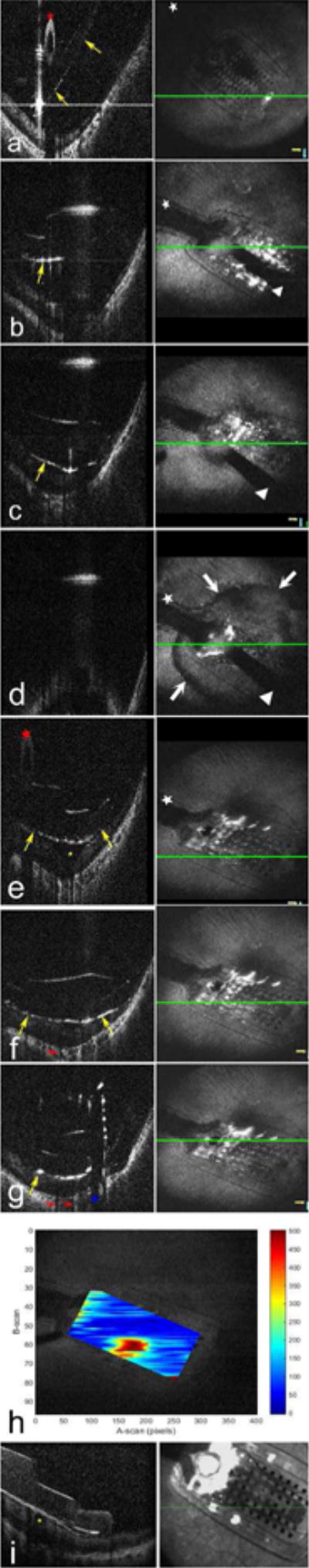
Intraoperative microscope-integrated high-speed (100,000 A-scans/second) swept-source optical coherence tomography (OCT) imaging: Sequential OCT B-scans (left column) and maximum intensity projection (MIP) en face MIOCT images (right column) during placement of the metallic retinal tack to secure the array. Prior to retinal tacking, the array (posterior array margins visualized as hyperreflective surfaces indicated by yellow arrows, the array handle visualized as a hyperreflective oval indicated by the red star, and the cable by the white star) is tilted on the retinal surface (a). As the 19-gauge tacking forceps (shadow cast by the forceps indicated with the white triangle) initially lowers the array towards the retina, the array is visualized still not fully apposed to the retinal surface (b). With progressive pressure with the tacking forceps, array apposition is visualized (c). Further pressure during tack placement results in posterior displacement of the globe, causing part of the image to temporarily move out of the OCT imaging range, resulting in a mirror image artifact on the B-scan and a circumferential darkening of the retinal surface surrounding the array on the en face MIP image (d, white arrows).
Following tack placement and release of the tacking forceps, the OCT images returns to within imaging range and B-scan confirms close approximation of the array with the inner retinal surface and centration over the foveal pit as shown by the yellow star (e). Post-retinal tack placement intraoperative MIOCT B-scans show appropriate position of the entire array as represented in the three shown locations (e-g). Note the close approximation of the array (yellow arrows) with the inner retinal surface (e-g) and centration over the foveal pit (e, yellow star). Shadowing is noted directly below the metal electrodes (e-g, red arrows) and under the metal tack (g, blue star), and penetration of the tack through the retinal layers therefore cannot be visualized with OCT. In contrast, the transparent polymer between these electrodes allows visibility of the underlying retina. Figure h shows a distance topography map demonstrating the electrode-inner retina distances in microns. The map was created using the Duke OCT Retinal Analysis Program (DOCTRAP) by manually segmenting the lower boundary of the array and inner boundary of the retina on each individual B scan. The area in red represents increased array-retina distance at the foveal pit.
Postoperative spectral domain OCT (Spectralis, Heidelberg, Germany) obtained in clinic 4 weeks post-implantation confirms continued optimal array position overlying the foveal pit (yellow star) without a visible shift in position between the intraoperative supine position (a-g) and postoperative sitting position in clinic (i).
Retinal tack placement (Figure 1b-f)
MIOCT allowed real-time visualization of retinal tack placement (Video). When using the tack forceps to secure the electrode array over the macula, pressure is applied perpendicular to the retinal surface to penetrate the tack through the sclera.5 On B scan images, array boundaries were visualized as hyperreflective surfaces and the array-handle as a hyperreflective oval. As pressure was applied with the tack forceps, array apposition was directly visualized on OCT.
Post retinal tack placement
After release of the tack forceps, MIOCT permitted intraoperative confirmation of electrode-inner retinal surface apposition (Figure 1e-g) and centration over the foveal pit. Electrode-inner retinal surface distances, which have been shown to correlate with threshold levels of electrode stimulation, were determined by manually creating a distance-map that also confirmed array centration over the foveal pit (Figure 1h).6 Array position variability in the intraoperative prone position and the postoperative standing or sitting position has been questioned.1 We confirmed this stability by comparing intraoperative and postoperative OCT scans (Figure 1i).
Dislodged or improperly positioned retinal tacks were reported in 2/30 (6.7%) eyes during clinical trials. Improper positioning was not noted in either case intraoperatively and both required revision surgeries.4 MIOCT-based intraoperative confirmation of array position can potentially avoid this scenario. MIOCT allows near real-time capture of volumetric data and the ability to view individual B-scans in any area of interest. This is in contrast to spectral-domain-based intraoperative-OCT systems, wherein an area of interest needs to be identified prior to image acquisition, and maintained in the same plane intraoperatively, which is challenging.
In conclusion, Argus II implantation with a prototype MIOCT device was successfully performed, enabling intraoperative cross-sectional visualization. MIOCT allowed realtime confirmation of array position pre-, intra- and post-tack placement and confirmed the adequacy of tacking in securing the array in close contact with the retina. This may help optimize outcomes and prevent known complications of Argus II implantation, and further investigation into its utility is warranted.
Supplementary Material
Acknowledgments
This report adhered to the principles of the Declaration of Helsinki. Duke University institutional review board approval was obtained.
The authors would like to acknowledge Christian Viehland and Brenton Keller for their contribution towards development of the MIOCT software.
Funding/Support:
This project was funded by the NIH Bioengineering Research Partnership Grant: R01-EY-023039 “Intraoperative OCT Guidance of Intraocular Surgery” (Izatt/Toth). Heed Ophthalmic Foundation (San Francisco, CA) and Ronald G. Michels Fellowship Foundation (Riderwood, MD) (DSG)
Footnotes
Supplementary Material
Video Caption: Microscope-integrated swept source optical coherence tomography (MIOCT) device for OCT acquisition simultaneous with surgical maneuvers during implantation of the Argus II retinal prosthesis. Surgical microscope view is shown on the left and the MIOCT B-scan and en face maximum intensity projections (MIP) video on the right. Real-time visualization of retinal tack placement is obtained. Post retinal tack placement MIOCT permitted intraoperative confirmation of approximation of electrodes to the internal retinal surface.
Conflict of interest:
All authors have completed and submitted the ICMJE Form for Disclosure of Potential Conflicts of Interest. Paul Hahn reports a consulting agreement with Second Sight Medical Products, Inc. Sylmar, CA. No other disclosures were reported. The authors have full control of all primary data.
Electronic supplementary material: Video is provided as Electronic supplementary material
Presentation at a conference
This paper has not been presented in any conference.
References
- 1.Rizzo S, Belting C, Cinelli L, et al. The Argus II Retinal Prosthesis: 12-month outcomes from a single-study center. Am J Ophthalmol. 2014;157(6):1282–1290. doi: 10.1016/j.ajo.2014.02.039. [DOI] [PubMed] [Google Scholar]
- 2.Ahuja AK, Behrend MR. The Argus II retinal prosthesis: factors affecting patient selection for implantation. Prog Retin Eye Res. 2013;36:1–23. doi: 10.1016/j.preteyeres.2013.01.002. [DOI] [PubMed] [Google Scholar]
- 3.Hahn P, Migacz J, O’Connell R, Izatt JA, Toth CA. Unprocessed real-time imaging of vitreoretinal surgical maneuvers using a microscope-integrated spectral-domain optical coherence tomography system. Graefes Arch Clin Exp Ophthalmol. 2013;251(1):213–220. doi: 10.1007/s00417-012-2052-2. [DOI] [PMC free article] [PubMed] [Google Scholar]
- 4.Ho AC, Humayun MS, Dorn JD, et al. Long-Term Results from an Epiretinal Prosthesis to Restore Sight to the Blind. Ophthalmology. 2015;122(8):1547–1554. doi: 10.1016/j.ophtha.2015.04.032. [DOI] [PMC free article] [PubMed] [Google Scholar]
- 5.Sight S. Argus II Retinal Prosthesis System Surgeon Manual. 2013 090001-004(900029-001 Rev C) [Google Scholar]
- 6.Ahuja AK, Yeoh J, Dorn JD, et al. Factors Affecting Perceptual Threshold in Argus II Retinal Prosthesis Subjects. Transl Vis Sci Technol. 2013;2(4):1. doi: 10.1167/tvst.2.4.1. [DOI] [PMC free article] [PubMed] [Google Scholar]
Associated Data
This section collects any data citations, data availability statements, or supplementary materials included in this article.