

Abstract
Microbutton rheometry reveals that the chiral morphology of dipalmitoylphosphatidylcholine (DPPC) monolayers imparts a chiral nonlinear rheological response. The nonlinear elastic modulus and yield stress of DPPC monolayers are greater when sheared clockwise (C), against the natural winding direction of DPPC domains, than counter-clockwise (CC). Under strong CC shear strains, domains deform plastically; by contrast, domains appear to fracture under strong C shearing. After CC shearing, extended LC domains develop regular patterns of new invaginations as they recoil, which we hypothesize reflect the nucleation and growth of new defect lines across which the tilt direction undergoes a step change in orientation. The regular spacing of these twist-gradient defects is likely set by a competition between the molecular chirality and the correlation length of the DPPC lattice. The macroscopic mechanical consequences of DPPC’s underlying molecular chirality are remarkable, given the single-component, non-cross-linked nature of the monolayers they form.
Keywords: Dipalmitoylphospatidylcholine, tilt-gradient lines, smectic liquid crystals, frustration
Graphical abstract
The macroscopic, mechanical response property of a monomolecular film of the phospholipid DPPC is chiral: values of nonlinear elastic moduli and yield stresses are quite different, depending on the direction of the applied torque; even healing processes after removing a large torque also exhibit completely different behaviors.
Introduction
Phospholipid monolayers form a plethora of liquid-crystalline phases, in which the molecules pack into hexagonal and pseudo-hexagonal lattices, and the tail groups tilt to accommodate the mismatch in projected area between the headgroup and the close-packed chains1–5. Complicating this packing, natural 1,2-dipalmitoyl-sn-glycero-3-sn-phosphocholine (r-DPPC) has an exclusively r-enantiomer chiral carbon. This induces a chiral orientational ordering in liquid-condensed (LC) domains that persists over tens of microns (Fig. 1), imparting a handedness that is retained even as the domains become close-packed (Figs. 1–2). The chiral twist demands that r-DPPC, and hence the chain tilt, rotate from the domain center to the periphery, which is incompatible with a regular lattice6–8. One solution adopted by many materials8–11 is to localize this required twist to defects9–11, or to expel the twist to the material boundaries8. In r-DPPC monolayers, this frustration between tilt and twist leads to “tilt gradient lines” across which tilt rapidly changes orientation6,7, as indicated in Fig. 1a. These discontinuous changes in tilt direction allow the chiral precession required globally, while maintaining a constant nearest-neighbor-directed tilt orientation locally6,7. Individual domains adopt a multi-lobed structure that winds in a counter-clockwise fashion (Fig. 1,2)7,12.
Fig. 1.

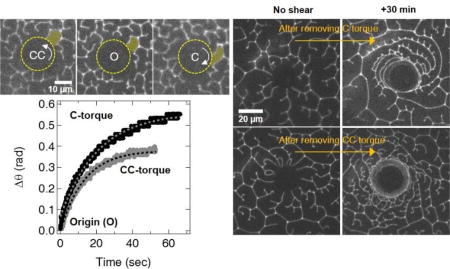
(a) Schematics for describing a tilt of DPPC molecules in a condensed domain. Each direction of the tilt (blue, orange, and green solid lines) is localized at three different lobes of the domain, respectively. Yellow dotted lines across the inside of the domain represents tilt gradient lines where the tilt direction changes abruptly. A enlarged image of a solid white circle at a center of the domain indicates a disclination pair (blue circles) that might facilitate to produce the tilt gradient lines. (b) Epifluorescence microscope images show liquid condensed (LC) r-DPPC domains (black) grow from a uniform liquid expanded (LE) phase (grey) with spiral arms that rotate in counter-clockwise (CC) direction, which is retained even in fully condensed state (3) at the co-existence plateau of the isotherm. The fraction of condensed domains increases with surface pressure from (1) to (3) (c) Domains (e.g. highlighted yellow example) are compacted when microbutton is CC-torqued (C-shear), but extended when C-torqued (CC-shear). O represents monolayer morphology before shear. (d) The limiting rotational strain, Δθl is greater for the same ~ 440 nN/m torque applied in the C direction than the CC direction, reflecting the chirality of the rheological response.
Fig. 2.

Effect of chirality on non-linear elastic modulus and yield stress. (a) Fluorescence images of 50/50 (racemic) and 75/25 r-DPPC/s-DPPC and 100% r-DPPC. As the ratio of r-DPPC to s-DPPC increases, the counterclockwise rotation of the domains increases. (b) The chiral nonlinear elasticity ratio G’c/G’cc increases linearly from 1 to 1.5 for (Xr-DPPC – Xs-DPPC) from 0.0 (racemic mixture) to 1.0 (pure r-DPPC) (c) Fluorescence images showing the area of r-DPPC monolayers yielded by microbuttons rotating at 6 Hz in the counter-clockwise (CC) and clockwise (C) directions. The yield radius Ry (arrow) is larger for monolayers with lower surface yield stresses. (d) Yield radius increases with rotation rate according to Eqn. 1, revealing the surface yield stress for C-sheared monolayers, , to be ~ 1.8 times higher than for CC-sheared , reminiscent of the nonlinear elasticity ratio.
Here we use our microbutton microrheology technique13 to show that the mechanical response of LC monolayers of DPPC is chiral as well: r-DPPC monolayers are stiffer when sheared clockwise (C) – against the natural winding of individual domains – than when sheared counter- clockwise (CC). These differences disappear for racemic DPPC. The surface yield stress and relaxation dynamics also show marked differences for shearing in the two senses. Domains deform plastically when sheared in their winding direction, but fracture when sheared against their natural winding direction. We argue that interactions between the tilt gradient boundaries and the applied shear connect the chirality of the macroscopic mechanical response with that of the molecules.
The mechanical response of other chiral materials also gives distinctive signatures14–18. The familiar helical structure of DNA couples its twisting and stretching deformations, even at the linear response level14,15, and chiral liquid crystals, subjected to oscillatory shear flows, also exhibit quite different rheological properties, depending on the direction of a helix vector with respect to the flow direction16–18. In contrast, relatively few demonstrations of chiral rheology in 2-dimensional systems have appeared in the literature19–21. The effects of chirality on mechanical properties arise in the coupling between compression, internal rotation, and chiral structure in specially-designed two-dimensional chiral honeycomb lattices20. Such materials can be described with Cosserat (micro-polar) constitutive relations, which introduce a rotational degree of freedom that depends upon the orientation of a micropolar angle relative to the lattice19,21. Nonetheless, the linear stress-strain response remains achiral even for Cosserat materials, because the linear elasticity tensor is invariant under inversion19,21. However, nothing prevents chiral materials from exhibiting a chiral response to larger deformations, as we reveal to occur in self-assembled, chiral r-DPPC monolayers.
Materials and Methods
Isotherms
Experiments were performed in a Teflon Langmuir trough of our design with dual barriers to provide symmetric compression at the trough center. The surface pressure, π (i.e., the reduction in surface tension of a clean air-water interface, π = γ0 − γ, γ0 = 72 mN/m at 25 °C) was measured using a filter paper Wilhelmy plate tensiometer (Riegler and Kirstein, Germany). A computer interface written in LabVIEW 9.0 (National Instruments, Austin, TX) handled all aspects of trough control and data collection. A 15 mm-diameter circular reservoir isolated part of the trough surface to minimize convective drift and help localize the micro-buttons (18).
1,2-dipalmitoyl-sn-glycero-3-phosphocholine (r-DPPC, R-enantiomer) (Avanti, Alabaster, AL) and racemic DPPC were purchased from Avanti Polar Lipids (Alabaster, AL) and used as received. For visualization studies, r-DPPC or mixtures of r-DPPC with the racemic mixtures were mixed with 0.05 wt% Texas-Red DHPE (N-(Texas Red sulfonyl)-1,2-dihexadecanoyl-sn-glycero-3-phosphoethanolamine, Invitrogen, Grand Island, NY) in the appropriate ratios and diluted to ~0.2 mg/ml in HPLC-grade chloroform (Fisher Scientific, St. Louis, MO) to form a spreading solution. The spreading solution was deposited dropwise onto the clean air-water interface from a Hamilton syringe (Reno, Nevada). 20 min were allowed for solvent evaporation prior to film compression. Contrast in the images results from the expulsion of the Texas-Red DHPE dye from the LC domains, which appear dark in a lighter background of less ordered LE phase in which the dye accumulates.
Interfacial Microrheology
Circular ferromagnetic probes (microbuttons) of diameter 20 µm, thickness 1 µm, with “button holes” of diameter 3.5 µm were fabricated by photolithography13,22. A layer of nickel was deposited via electron-beam evaporation onto one side of the microbutton, followed by a 10 nm layer of gold, and the entire wafer was dipped into a 1.0 mM solution of perfluorooctanethiol (Sigma, St. Louis, MO) in ethanol to form a hydrophobic self-assembled monolayer on the gold. A drop of microbuttons in isopropyl alcohol was added to the trough; the microbuttons float to the interface and the hydrophobic surface coating orients the Janus microbuttons gold (hydrophobic) side towards the air. The magnetic moments of the microbuttons, m = (50 ± 11) × 10 −10 emu for the 150 nm thick nickel and (6.9 ± 2.3) × 10−10 emu for the 50 nm thick nickel13,23, were determined by placing the microbuttons on the water/air interface and measuring the rotational response to a known magnetic field.
A uniform magnetic field of magnitude, B, and orientation, ϕ, was generated by the output of two independent pairs of electromagnets controlled by a custom LabVIEW code13,23 to exert a controlled torque, τ, on a microbutton of moment M and orientation θ⃗ : τ = M × B = mBsin(ϕ − θ). The orientation of the microbutton, θ⃗ is determined by tracking the buttonholes using a custom image analysis program written in Labview. Here, two operation modes are used. In creep mode, the magnetic field is applied perpendicular to the orientation of the microbutton to maintain a constant torque. In the constant strain-rate mode, two strong sinusoidal magnetic fields are applied with 90° of phase difference at a fixed frequency to rotate the microbuttons at a fixed rotation rate. The microbuttons (dotted yellow circles in Fig. 1c) are strongly anchored to the monolayer along their perimeter. For all measurements reported here, the Boussinesq number is >>113,23, meaning that the drag on the microbutton is dominated by the monolayer.
Pre-shear
The nonlinear elastic response is complicated by an initial slip between domains along grain boundaries (Fig. S1 1–3). To eliminate these effects, we begin each measurement by applying a pre-torque that causes domains to initially slip, then deform elastically. When the external torque is removed, the elastically-deformed domains relax, but do not return completely to their original configuration, leaving some residual strain behind (Fig. S1 1–3). Subsequent torques, applied in the same direction, deform the domains without this initial slip, so that complete strain recovery is observed, and repeatable elastic modulus measurements can be made (Fig.S1).
Results and Discussion
Increasing the surface pressure of a r-DPPC monolayer (Fig. 1b) causes the nucleation and growth of semi-crystalline liquid condensed (LC, dark) domains from the disordered liquid expanded (LE, bright) phase at the coexistence surface pressure (Fig. 1b, inset 1). The LC phase grows into 10 – 50 µm domains with multiple lobes, which rotate counter-clockwise from the domain center to the periphery (Fig. 1b, inset 2). Compression through the coexistence plateau causes the spiral DPPC domains to pack together like pieces in an puzzle, which requires LC domains to deform in coordination with their neighbors (Fig. 1b)(13). The fluorescent dye is concentrated at the domain boundaries, and areas of increased molecular disorder (bright lines in Fig. 1b, inset 3), allowing individual domains to be visualized as they deform.
Non-linear monolayer deformations are driven by magnetically torqueing a 20 µm diameter ferromagnetic microbutton3,22 within an r-DPPC monolayer (Fig. 1c). The rheological response is visualized by monitoring the rotation of the microbutton and the surrounding monolayer in response to an applied torque T0. The shear stress, τrθ, on the monolayer is in the opposite direction of the applied torque, and decreases with the inverse square of the distance, r, from the microbutton center:
| (1) |
Here, equation (1) is valid when r ≥ a (the radius of the microbutton). If the monolayer is yielded, τrθ = −T0/2πRy2, where Ry is a yielded radius (Fig. 2c), and otherwise, τrθ = −T0/2πa2. Applying clockwise (C) or counterclockwise (CC) torques on the microbutton probe shears the monolayer in the CC and C directions, respectively (Fig. 1, 2).
The close-packed LC domains deform in coordination with their neighbors as shown in Fig. 1c; the highlighted domain is compacted when the microbutton is rotated counterclockwise (opposite the natural winding of DPPC), but stretched when rotated clockwise (C). The line tension at the domain boundaries imparts an elastic response to the rotation, and the surface viscosity within each LC grain limits the rate with which deformed domains relax, a 2-D analog to 3-D emulsion droplets13.
Fig. 1d shows the response to a ~ 0.3 nN·µm microbutton torque, which is large enough to shear the monolayer beyond its symmetric linear viscoelastic response, but below its yield stress13,23. Surprisingly, the C-torqued microbutton rotates 1.5 times further than the CC-torqued microbutton. Evidently, shearing a domain in its natural winding direction (CC; torque in C direction) is energetically less costly than shearing it against the natural winding of the domain. From the measured limiting rotational strain, Δθl, of the microbutton in response to the imposed torque τapp, (Fig. 1d), we compute a non-linear elastic modulus, G′ ≈ T0/2πa2Δθl, in which a is the microbutton radius. This assumes the monolayer exhibits homogeneous, continuum properties, and that stresses due to the monolayer overwhelm those from the subphase (the high-Boussinesq number limit13,23).
The nonlinear elastic modulus of r-DPPC monolayers is 50% greater when sheared against the natural CC winding direction of the domain, than with it; the ratio of nonlinear elasticities for shear in the C direction, G′C relative to the shear in the CC direction, G′CC, G′C/G′CC ≈ 1.5.
By contrast, the morphology of a racemic monolayer (1:1 mole ratio of r:s) is achiral (Fig. 2a), and the nonlinear elasticity ratio, G′C/G′CC ≈ 1 (Fig. 2b). The domains show increasing CC handedness with increasing r-DPPC fraction; correspondingly, G′C/G′CC increases linearly from 1 to 1.5 with enantiomeric excess, X = (Mole fraction r)-(mole fraction s). This specific chiral nonlinear elasticity ratio is not universal, but likely depends on the magnitude of the applied torque and conditions of the monolayer.
A constant microbutton rotation causes the monolayer to yield, creating a flowing (yielded) region close to the microbutton, where interfacial stresses exceed the surface yield stress Ys, surrounded by a steadily-deformed, non-flowing region, where the interfacial stresses are weaker than Ys (Fig. 2c)13,23. Fluorescent dye accumulates at a bright slip line (tips of yellow arrows), defining the yield radius Ry at which the surface shear stress is equal to the surface yield stress Ys. The yield radius can be related to rotation rate by assuming torque to be conserved within the monolayer13,23, surface viscosity μS to be constant within the flowing region, and azimuthal velocity to decay from Ωa at the microbutton radius to zero at Ry, giving
| (2) |
The surface yield stress of r-DPPC monolayers sheared in the C direction (CC-torqued button), , exceeds that of CC-sheared r-DPPC monolayers (C-torqued button), (Fig. 2d). The chiral yield stress ratio, , is similar to the ~ 1.5 chiral nonlinear rheology ratio from Fig. 2b.
Chirality also determines domain evolution during sustained shear. The initial morphology of r-DPPC monolayers (Fig. 3 a, e) deforms differently in response to 5 minutes of steady 6 Hz rotation in the C (CC-shear, Fig. 3b) or CC (C-shear, Fig. 3f) directions. Individual LC domains within the yield radius are thin enough that they cannot be optically resolved (Fig. 3b, f). The non-flowing region outside the yield radius contains extended, elastically-deformed LC domains that can be mapped back to the initial morphology via smooth deformations (Fig 3a, e). Both C- and CC-shearing increase the total length of the bright lines, thereby increasing the total line tension energy. Once the applied torque is removed, the deformed domains contract in the direction opposite the rotation while restoring their width in the direction normal to the microbutton (Figs. 3c,d;g,h), presumably relaxing towards lower-energy shapes at a rate resisted by the intra-domain interfacial viscosity3,13,23,24.
Fig. 3.

Monolayer evolution after five minutes of sustained CC- (top row, torque in C direction) or C- (bottom row, torque in CC direction) shearing. (a), (e) Fluorescence micrographs show morphology of bright, fluorescently labeled domain boundaries before shearing. Monolayer morphology after steady microbutton rotation at 6 Hz for 5 minutes in C-direction (b) or CC-direction (c). As in Fig. 2c, the yield radius is larger when CC-sheared (b) than C-sheared (f). No new defect lines appear, although C-sheared domains are rotated and compacted, while CC-sheared domains are stretched. (c) Five minutes after torque is removed, extended domains emerge from yielded region of CC-sheared domains (c), but not from C-sheared (g). (d) 30 min after external torque is removed, CC-sheared monolayers contain primarily elongated domains with multiple, regularly-spaced defect lines oriented away from the microbutton. By contrast, (h) small ‘shards’ emerge from yielded, C-sheared regions, suggesting the original domains fractured during the initial shear.
However, pronounced differences occur as the monolayers recover from steady C- and CC-shears. Figs. 3c–d show that elongated domains emerge from the yield regions created by CC-shearing, suggesting domains that had stretched and wrapped like an elastic thread around a spool. By contrast, Figs. 3g–h reveal small, shard-like fragments that slowly emerge from the yielded region of C-yielded monolayers. It appears that strongly nonlinear CC-shears, in the same direction as the natural orientation of the r-DPPC, deform the domains in a smooth, ductile, and plastic fashion (Fig. 3b–d). Strongly nonlinear C-shears, on the other hand, go against the CC-winding of the spiral arms of the domains, causing their fracture (Fig. 3f–h).
Bright defect lines also evolve differently after shearing in the two senses. CC-sheared domains, which stretched plastically into long, extended domains without forming new defect lines, develop a series of regularly spaced defect lines of near equal length during relaxation, but only on the concave side of the existing domain boundary lines, pointing radially outward from the microbutton. (Fig 3d, top, Fig. 5). By contrast, few, if any, new defects appear in the compacted, C-sheared (CC torqued) domains as they relax after shear (Figs. 3e–h). Even though the CC-torqued yielded region was smaller than the C-torqued yielded one, the C-torqued region relaxed fully after 30 minutes, while the CC-torqued yielded region had not yet relaxed, even after a full hour. The total domain boundary length (bright lines) after 30 minutes of relaxation (Fig. 3h) is significantly greater than its initial state (Fig. 3e), corresponding to higher line tension energy and suggesting a healing process that is still ongoing, via very slow annealing of defect lines (Fig. S2b).
Fig. 5.

Nucleation and growth of tilt-gradient linesas monolayers ‘heal’ after C-torque is removed. (a) Upon removing the external torque (0 min), elongated domains begin to retract and widen. Regularly spaced invaginations (yellow boxes) begin to appear along the concave side of extended domains approximately 11 minutes after torque removal, which grow as the monolayer relaxes (11–30 minutes). (b) Magnified images of yellow boxes, with new lines highlighted in yellow. (c) The spacing between neighboring defect lines is sharply peaked at 5.9 ± 1.4 µm.
One explanation for the different effects of C vs CC shear is the coupling between the tilt and chiral twist in the domains (Fig. 4). Brewster angle25 or polarized fluorescence microscopy6,7,26 show the tilt orientation is uniform over large areas of the domains, with discontinuous jumps across “tilt-gradient” lines6,26. The tilt gradient lines originate from disclination pairs at the domain core6,7 and terminate at the invaginations in the domains where the bright, dye rich lines abruptly end6,7. These regions of uniform tilt are relatively constant in width, suggesting a balance between the molecular correlations and the strain induced by the chiral twist. Beyond a critical width, a tilt gradient line is necessary to allow the tilt direction to precess, typically by a discrete angle consistent with the underlying hexagonal packing6,7. As the tilt-gradient lines are less ordered, they represent high energy regions within the crystal, corresponding to weak zones within the domains. The yellow dotted lines depict possible locations of these tilt-gradient lines within the domain in Fig. 4O, which dividing the domain into three roughly equivalent, kidney-shaped regions.
Fig. 4.

O shows the original, unstressed configuration of a typical three-lobed DPPC domain. Dashed, yellow circle outlines approximate domain core, with dotted yellow lines tracing possible tilt gradient line locations, which divide the domain into three equivalent kidney shaped regions. Left: Photographically C-shearing the monolayer (CC-torque) ‘unwinds’ the spiral arms from the domain core, exerting a tensile stress at the junction (inset, left) that promotes crack initiation and propagation. By contrast, CC-shear (C-torque, right) over-winds the spiral arms (bottom right), compressing them against the domain core, so that they stretch without breaking.
To illustrate the effects of shear, Fig. 4C(right) is photographically sheared in the CC-sense (C torque), while 4CC (left) is photographically sheared in the C-sense (CC torque). The C shear (CC torque) acts to effectively ‘unwind’ each spiral arm away from its center. Mechanically, the ‘unwinding’ of each spiral arm naturally exerts a tensile stress on the junction between the spiral arm and the domain core, which coincides with the location where high-energy tilt gradient lines terminate. In essence, domain arms act like levers to focus the tensile stress at invagination tips – a key ingredient for crack initiation – which are co-located with high-energy tilt-gradient lines – which naturally promote crack propagation.
The CC-shear that results from the C torque, on the other hand, over-winds the spiral arms, exerting a compressive stress on the junction between the core and the spiral, which therefore provides no driving force for crack initiation or propagation (Fig 4C, right). By contrast, over-winding these C-sheared domains pushes the spiral arms beyond the conditions where the precessing chiral twist can be accommodated without new tilt gradient lines. We argue that the nucleation and growth of multiple, regularly-spaced bright invaginations (Fig. 5) relieve the tension between the chirality-enforced precession of the tilt and the alignment of tilts locked in a single direction dictated by the hexagonal head-group lattice. These new tilt-gradient lines introduce new local minima into the configurational free-energy, slowing or arresting further domain relaxation.
Fig. 5 shows the time evolution of the monolayer following the removal of a steady C-torque (CC-shear). Long, thin domains bordered by continuous bright defect lines unwind from the yielded region and shorten and thicken. These extended two-dimensional domains are not susceptible to break-up under the Plateau-Rayleigh instability, due to the absence of out-of-plane curvature, unlike three-dimensional fluid cylinders13. Once the imposed stress is removed, the line tension of the still-continuous boundaries acts to pull the domains back into more compact and energetically favorable configurations. In particular, after 30 minutes, a total length of the continuous bright boundaries is almost identical to that of the initial configuration, as indicated in Fig. S2, thereby strongly suggesting that this line tension energy of the bright boundaries determine the healing process mainly. Furthermore, after approximately 11 minutes, a regular array of new bright lines nucleates and extends, always pointing away from the microbutton. These bright lines indicate locally disordered regions which increase the solubility of the fluorescent dye, and are consistent with the termination of newly-forming tilt gradients lines within the (dark) LC grains (Fig. 5, 11min) that then propagate into the extended domain arm (Fig. 5b, 11–30 min). Fig. 5c shows the distance between new defect lines to be distributed with a sharp peak at 5.9 ± 1.4 µm.
This series of regularly spaced defects that balance twist and repetitive layers or lattices is reminiscent of de Gennes’ analogy between superconductors and smectic A liquid crystals27. de Gennes showed that chiral twist or bend distortions in layered materials are analogous to magnetic fields applied to superconductors27. In superconductors, the magnetic field is either expelled (type-I behavior) or incorporated into the Abrikosov flux lattice (type-II behavior) depending on the ratio of the penetration depth of the magnetic field to the correlation length of the superconductor, as represented by the Landau-Ginzburg parameter27. de Gennes suggested that bend or twist of regularly layered structures could be accomplished by a periodic network of edge dislocations, that form the equivalent of tilt gradient lines. Such tilt boundaries preserve the regular layer spacing, except at the tilt boundaries, where a jump occurs in the tilt orientation. Brewster angle25 and polarized fluorescence microscopy6,7,26 confirm the tilt orientation is uniform over the lobes of DPPC domains, with discontinuous jumps across “tilt-gradient” lines. Hatta28 showed it to be energetically favorable to localize edge dislocations at these tilt gradient lines. Following plastic deformation of the monolayer, the mobile dislocations re-align over time to restore the tilt gradient lines28. The spiral rotation imposed by the chiral center of DPPC is facilitated by a regular spacing of these dislocation-mediated tilt gradient lines6,7.
In line with this speculation, the rotation of the domains in r-DPPC monolayers can be increased by adding small amounts (0.1 – 4 mol%) of cholesterol (Fig. S3). The added cholesterol decreases the correlation length of the lattice3 but the twist penetration length likely remains the same, since the r-DPPC head group is unchanged. This increases the analogous Landau-Ginzburg parameter27, resulting in more closely spaced tilt gradient lines, increasing the rotation of the r-DPPC domains, as is shown in Fig. S3.
Conclusions
Previously, we had shown DPPC monolayers to behave like compressed, two-dimensional emulsions: materials whose molecular constituents remain exclusively in liquid phases, yet which respond like viscoelastic solids with a finite yield stress13. DPPC monolayers thus behave like the 2D analog of mayonnaise, which sits without flowing on a slice of bread, yet which can be spread easily with a knife. The absence of the Rayleigh-Plateau instability in 2D added an additional curiosity: continuously sheared and yielded DPPC monolayers recoil and heal for tens of minutes once the shearing is removed. Continuing the analogy, this would correspond to mayonnaise spontaneously ‘unspreading’ from bread once the knife was lifted.
Our present results reveal an additional, remarkable twist: that r-DPPC monolayers respond in a chiral fashion to strong stresses. DPPC domains shatter when sheared in a clockwise sense, yet deform like ductile plastic solids when sheared counter-clockwise. Pushing the mayonnaise analogy even further, r-DPPC behaves like a condiment that shatters when spread to the left, but stretches when spread to the right!
This remarkable mechanical chirality arises due to a chiral center in DPPC, where the head group and the two hydrophobic tails are attached. Morphologically, this molecular chirality has long been known to be manifested macroscopically by a chiral domain morphology which disappears for racemic mixtures (Figs. 1 and 2)29. Interfacial rheology is exquisitely sensitive to this molecular packing3,23,30; interfacial microbutton rheometry shows for the first time that this chiral morphology leads to chiral nonlinear rheology. The nonlinear elastic modulus G’ and yield stress YS of r-DPPC monolayers are greater when sheared clockwise (C) than counter-clockwise (CC). DPPC monolayers exhibit greater resistance to strong deformations that act against the natural CC winding of the domains, than to those that act with the domain winding.
As is often the case with complex fluids, the complex macroscopic response follows from the dynamics of the mesostructure and morphology. Direct visualization of the deforming domains shows qualitatively different nonlinear domain evolution for CC and C deformations. Strong CC shear, which tends to over-wind LC r-DPPC domains, stretches spiral arms while compressing them against domain cores. CC-sheared domains deform in a ductile fashion, and deform plastically. By contrast, strong C-shear acts to ‘unwind’ the spiral arms of r-DPPC domains, each of which acts like a lever that focuses a tensile stress at the domain/arm junction. We argue these conditions to promote fracture events within C sheared domains. Furthermore, this picture is consistent with the mechanics of tilt gradient lines – invisible in our experiments – at which the tilt direction undergoes a step change in orientation over a narrow region, in order to resolve two conflicting forces: (1) phospholipid tails tend to tilt and align with their neighbors in a direction locked to the head group lattice, and (2) molecular chirality drives the tilt orientation to precess with distance from the domain core. Because tilt gradient lines represent weak (high-energy) lines, we hypothesize that they facilitate crack propagation in C-sheared domains. By contrast, the highly-extended domain shapes formed by strong CC shear cannot satisfy the balance between tilt alignment and precession via smooth deformations. Instead, we argue that new tilt gradient lines must be created (Fig. 5) to allow the rapid reorientation of the tilt direction, while preserving the local tilt orientation over the rest of the domain. We rationalize the regular spacing of these twist-gradient arrays is set by a competition between the twist penetration length due to the chiral center of DPPC, and the correlation length of the DPPC molecular lattice10,11,27,31.
Supplementary Material
Acknowledgments
The authors acknowledge support from National Institutes of Health Grants HL 51177, HL 135065 and NSF Grant CBET 170378 and the Basic Science Research Program through the National Research Foundation of Korea, NRF-2015R1C1A1A01054180, (KHK, SQC).
Footnotes
Conflicts of interest
There are no conflicts to declare.
References
- 1.Kaganer V, Möhwald H, Dutta P. Rev. Mod. Phys. 1999;71:779–819. [Google Scholar]
- 2.Zasadzinski JA, Viswanathan R, Madsen L, Garnaes J, Schwartz DK. Science. 1994;263:1726–33. doi: 10.1126/science.8134836. [DOI] [PubMed] [Google Scholar]
- 3.Choi SQ, Kim K, Fellows CM, Cao KD, Lin B, Lee KYC, Squires TM, Zasadzinski JA. Langmuir. 2014;30:8829–8838. doi: 10.1021/la501615g. [DOI] [PMC free article] [PubMed] [Google Scholar]
- 4.McConnell HM. Annu. Rev. Phys. Chem. 1991;42:171–195. [Google Scholar]
- 5.Seul M, Andelman D. Science. 1995;267:476–483. doi: 10.1126/science.267.5197.476. [DOI] [PubMed] [Google Scholar]
- 6.Dreier J, Brewer J, Simonsen AC. Soft Matter. 2012;8:4894. [Google Scholar]
- 7.Dreier J, Brewer J, Simonsen AC. Langmuir. 2014;30:10678–10685. doi: 10.1021/la5023054. [DOI] [PubMed] [Google Scholar]
- 8.Gibaud T, Barry E, Zakhary MJ, Henglin M, Ward A, Yang Y, Berciu C, Oldenbourg R, Hagan MF, Nicastro D, Meyer RB, Dogic Z. Nature. 2012;481:348–351. doi: 10.1038/nature10769. [DOI] [PubMed] [Google Scholar]
- 9.Goodby JW, Waugh MA, Stein SM, Chin E, Pindak R, Patel JS. Nature. 1989;337:449–452. [Google Scholar]
- 10.Ihn KJ, Zasadzinski JAN, Pindak R, Slaney AJ, Goodby J. Science. 1992;258:275–278. doi: 10.1126/science.258.5080.275. [DOI] [PubMed] [Google Scholar]
- 11.Fernsler J, Hough L, Shao R-F, Maclennan JE, Navailles L, Brunet M, Madhusudana NV, Mondain-Monval O, Boyer C, Zasadzinski J, Rego JA, Walba DM, Clark NA. Proc. Natl. Acad. Sci. U. S. A. 2005;102:14191–6. doi: 10.1073/pnas.0500664102. [DOI] [PMC free article] [PubMed] [Google Scholar]
- 12.Ignés-Mullol J, Claret J, Sagués F. J. Phys. Chem. B. 2004;108:612–619. [Google Scholar]
- 13.Choi SQ, Steltenkamp S, Zasadzinski JA, Squires TM. Nat. Commun. 2011;2:312. doi: 10.1038/ncomms1321. [DOI] [PMC free article] [PubMed] [Google Scholar]
- 14.Lionnet T, Joubaud S, Lavery R, Bensimon D, Croquette V. Phys. Rev. Lett. 2006;96:178102. doi: 10.1103/PhysRevLett.96.178102. [DOI] [PubMed] [Google Scholar]
- 15.Gore J, Bryant Z, Nöllmann M, Le MU, Cozzarelli NR, Bustamante C. Nature. 2006;442:836–9. doi: 10.1038/nature04974. [DOI] [PubMed] [Google Scholar]
- 16.Helfrich W. Phys. Rev. Lett. 1969;23:372–374. [Google Scholar]
- 17.Rey AD. J. Rheol. 2000;44:855. [Google Scholar]
- 18.Salili SM, Kim C, Sprunt S, Gleeson JT, Parri O, Jákli A. RSC Adv. 2014;4:57419–57423. [Google Scholar]
- 19.Lakes R. Int. J. Mech. Sci. 2001;43:1579–1589. [Google Scholar]
- 20.Prall D, Lakes RS. Int. J. Mech. Sci. 1997;39:305–314. [Google Scholar]
- 21.Mindlin RD. Int. J. Solids Struct. 1965;1:265–271. [Google Scholar]
- 22.Choi SQ, Jang SG, Pascall AJ, Dimitriou MD, Kang T, Hawker CJ, Squires TM. Adv. Mater. 2011;23:2348–2352. doi: 10.1002/adma.201003604. [DOI] [PubMed] [Google Scholar]
- 23.Kim K, Choi SQ, Zasadzinski JA, Squires TM. Soft Matter. 2011;7:7782. [Google Scholar]
- 24.Kim K, Choi SQ, Zell ZA, Squires TM, Zasadzinski JA. Proc. Natl. Acad. Sci. U. S. A. 2013;110:E3054–60. doi: 10.1073/pnas.1303304110. [DOI] [PMC free article] [PubMed] [Google Scholar]
- 25.Moy VT, Keller DJ, Gaub HE, McConnell HH. J. Phys. Chem. 1986;90:3198–3202. [Google Scholar]
- 26.Bernchou U, Brewer J, Midtiby HS, Ipsen JH, Bagatolli LA, Simonsen AC. J. Am. Chem. Soc. 2009;131:14130–1. doi: 10.1021/ja903375m. [DOI] [PubMed] [Google Scholar]
- 27.de Gennes PG. Solid State Commun. 1972;10:753–756. [Google Scholar]
- 28.Hatta E. Langmuir. 2015;31:9597–9601. doi: 10.1021/acs.langmuir.5b02249. [DOI] [PubMed] [Google Scholar]
- 29.Weis RM, McConnell HM. Nature. 1984;310:47–49. doi: 10.1038/310047a0. [DOI] [PubMed] [Google Scholar]
- 30.Boyd E, Harkins WD. J. Am. Chem. Soc. 1939;61:1188–1195. [Google Scholar]
- 31.Renn SR, Lubensky TC. Phys. Rev. A. 1988;38:2132–2147. doi: 10.1103/physreva.38.2132. [DOI] [PubMed] [Google Scholar]
Associated Data
This section collects any data citations, data availability statements, or supplementary materials included in this article.