

Abstract
There are various algorithms currently in use to detect asteroids from ground-based observatories, but they are generally restricted to linear or mildly curved movement of the target object across the field of view. Space based sensors in high inclination, low Earth orbits can induce significant parallax in a collected sequence of images, especially for objects at the typical distances of asteroids in the inner Solar System. This results in a highly non-linear motion pattern of the asteroid across the sensor, which requires a more sophisticated search pattern for detection processing. Both the classical pattern matching used in ground based asteroid search and the more sensitive matched filtering and synthetic tracking techniques, can be adapted to account for highly complex parallax motion. A new shift vector generation methodology is discussed along with its impacts on commonly used detection algorithms, processing load, and responsiveness to asteroid track reporting. The matched filter, template generator, and pattern matcher source code for the software described herein are available via GitHub.
Keywords: techniques: image processing—minor planets, asteroids: general
1. Introduction
Searching for asteroids by collecting a sequence of star field imagery, either via a space-based observing platform or using multiple and widely separated ground-based telescopes, amplifies a unique measurement property only weakly seen from a single ground telescope. That property is the induced parallax motion, also referred to as curvature, of the asteroid’s motion across the sensor. The path that an imaging satellite follows while in low Earth orbit (LEO), as it moves with the Earth through the Solar System, can manifest itself as a three-dimensional helix bent along the Earth’s orbit around the Sun. That motion when projected onto the sensor’s focal plane, induces a complexly shaped sinusoidal-like “parallax shift” of a main belt asteroid or closer near-Earth object (NEO) against the background stars. For example, the Hubble Space Telescope (HST) sees this effect when taking long exposures and pointing near the ecliptic plane of the Solar System1. Similarly, if ground-based telescopes widely spaced across the surface of the Earth, perform a coordinated image observation of the same star field, then an NEO will also appear shifted in each viewpoint relative to the fixed stars. For a sun synchronous LEO satellite this can amount to as much as 19 arc-seconds in cross-track motion for an asteroid 1 AU distant. Depending on the discrete times of collection, the appearance is like a zig-zag of measurement positions rather than a gentle curve of points in the multi-frame sequence. In contrast, over the observation time of a typical asteroid survey image sequence of two hours taken of a 1 AU distant NEO, a single ground-based telescope would nominally see only a linear or a gently curved propagating track. It would have a cross-track deviation of up to 3 arc-seconds depending on encounter geometry, and only as high as 1.25 arc-seconds in opposition searches. Obviously NEOs closer than 1 AU show significantly more non-linear parallax effects for both ground and space-based sensors and thus needs to be accounted for in detection processing pipelines.
This parallax motion has been detected in ground-based surveys that perform opposition searches, but more often than not, the curvature is buried in a combination of seeing and the point spread function (PSF) blur of the instrument, nominally 1 arc-second or greater. Nevertheless, the various survey systems in operation today do attempt to account for some curvature of motion in their detection processing. The Catalina Sky Survey (CSS) does not directly include a curvature component in their linear-motion velocity match algorithm, but it is implied by the detection algorithm’s tolerance to small non-linearity that is of the order of the PSF width of the CSS instrumentation (Larson, 2018, personal communication). The Pan-STARRS algorithm document (Denneau et al., 2013) discusses the use of a linear velocity match for intra-day collections taken over short time intervals of hours that are used to form tracklets. Those tracklets are then linked over multiple days allowing for quadratic motion between the measurements (Kubica et al., 2007). Pan-STARRS and the Asteroid Terrestrial-impact Last Alert System (ATLAS) have extended that with an algorithm that handles mild curvature of up to 4 arc-seconds in cross-track curvature for the intra-day tracklet detection (Jedicke, 2018, personal communication). For space-based collection, the HST has experienced NEAs “photobombing” their imagery with long snaking trails (Evans et al., 1998), but they have no automated processing in place for detecting these inner Solar System asteroids. The HST Advanced Camera for Surveys has been used for distant Trans-Neptunian Object (TNO) searches (Bernstein et al., 2004) where 24-hour curvature of the tracks was included in the digital tracking method employed. Other groups performing TNO search from ground-based telescopes, have also dealt with the curvature associated with collections taken across multiple days. In one approach (Parker and Kavelaars, 2010), a set of hypothetical TNO orbits are generated, and their projected non-linear motion patterns are culled down to limit the number of patterns to test against the measurements. The curvature is thus accounted for by using a complete set of realizable TNO orbits and a simple Earth induced retrograde motion over the time of collection and tracklet linkage.
The algorithm described in this paper deviates from these approaches in two distinct ways. First, an attempt is made to account for the dramatically changing position of the sensor between the individual frames collected, which will be used to guide the detection algorithm. For example, this can arise from the rapid motion of a LEO satellite that may take four images at a wide variety of true anomalies in the satellite’s orbit, covering one and a half revolutions (~140 minutes) around the Earth. This was the basic operational scenario that was to be carried out by the Near-Earth Object Surveillance Satellite (NEOSSat) whose goal was to search for objects with orbits inside the Earth’s orbit (Hildebrand et al., 2007). Such a collection scenario would result in the NEO producing a zig-zag motion on the sensor against the fixed background stars, and thus the sensor platform’s heliocentric state vector at each frame time becomes a critical input to forming search patterns (templates comprised of multi-frame shift vectors) used in a matched filter detector.
The second deviation from previous work, is the recognition that there exists a single unique motion template as projected onto the focal plane of the sensor, from which all other hypothesized motion templates could be derived at the resolution of the PSF of the system. This places the motion pattern generation for all realizable NEO orbits in the more natural focal plane system of coordinates for a detection algorithm (encompassing two dimensions of pixel row and column), rather than hypothesizing six dimensional Keplerian orbital parameters and culling nearly equivalent motion patterns.
For the purposes of this paper, it will be assumed that the imaging sensor is onboard a LEO satellite with a nominal 90-minute orbital period and the system is expected to download full frame imagery to a ground site. With data on the ground, there would be no constraint placed on algorithmic complexity or available computing resources, since a runtime issue could be mitigated by simply employing multi-processor systems, GPUs, or cluster type architectures. Note that the detection reporting timeline to schedule follow-up observations can be a critical factor with space-based systems and may drive the processing algorithm recommendation towards a dual pass processing solution. For example, in a scenario with a very rapid processing turnaround requirement of under two-hours, the best solution may be to use a fast pattern matching capability to permit dynamic satellite tasking response timeliness, and a second slower but more sensitive matched filter or synthetic tracking processing capability to detect, as close as practicable, down to the noise limit of the imaging system. Note that pattern matching algorithms threshold each image independently, whereas matched filtering and its close relative synthetic tracking, hypothesize object motions and integrate the target energy across frames before thresholding to obtain a signal-to-noise ratio (SNR) gain.
More generally, this paper will focus on the characterization of the parallax motion, the discovery of a unique “zero motion” template, formulation of “bounding” templates to reduce the number of motion hypotheses, the limitations of the algorithm for close NEOs, and the impacts of the motion hypothesis templates on various commonly used detection algorithms. This will be done mostly in the context of a space-based imaging system but is equally applicable to a multi-station and spatially separated ground collection scenario.
2. Parallax Motion Characterization
To appropriately interface to moving-object detection algorithms, one must first understand the nature of parallax motion on the sensor’s focal plane and the general concept of motion templates used in the later sections. Motion templates or discrete point propagating patterns, form the basis of input to both pattern matching and matched filter algorithms. Motion templates can be smeared tracks arising from the moving-object covering more than one pixel during the integration time of a frame. But in typical moving-object search surveys, a template is characterized as a series of discrete points, as the objects of interest are unresolved point sources and the integration times are often chosen to avoid smear of the target and its associated trailing losses. In either case, general motion templates were found to be derivable from a single “zero-motion” template at one sensor-to-NEO range and are applicable to nearly all ranges except very close fly-by NEOs.
2.1 Sensor-Location Induced Parallax
In the classic ground-based NEO search strategy, a telescope revisits the same patch of sky multiple times over a short period of time (typically three to five images taken within two-hours). When the image sequence is registered to the background stars, an NEO will show displacement from frame-to-frame due to its relative motion to the telescope. This motion can be revealed using a moving target detector. In this scenario, the telescope is fixed to the Earth’s surface and thus moves with the Earth as it orbits the Sun, resulting in essentially a nearly straight line over the short time intervals of an imagery sequence collection. This is also true for the NEO moving in an elliptical orbit, which presents a nearly linear trajectory over short time scales. But the Earth is also rotating on it axis, so the telescope site is oscillating in heliocentric coordinates parallel to the Earth’s equatorial plane over the course of 24 hours. In two hours, the net displacement is at most 3300 km at the equator near dawn or dusk, and normally considerably less. Ground surveys often point in the opposition direction and main-belt asteroids tend to cluster along the ecliptic plane. Since the equatorial and ecliptic planes are at canted 23.5° with respect to each other, the Earth’s axial rotation induces mostly a change in range to the NEO from the telescope’s perspective and very little orthogonal movement off the relative orbital motion (i.e., parallax). While parallax does exist, the amplitude is typically less than an arc-second and below the sensor PSF of most surveys. Therefore ground-based surveys almost always show linearly propagating asteroids in their image sequences.
The situation is different if two or more telescopes observe the same patch of sky from widely different latitudes, or a space-based imaging sensor performs an NEO survey from low Earth orbit. Note that for a satellite in geosynchronous orbit, the parallax behavior is similar to a ground observatory, since the satellite is in an equatorial orbit. Thus, a polar orbiting or moderate inclination satellite orbit is a required feature for inducing significant parallax. For a polar orbiter at 400 km altitude, the largest swing in the baseline orthogonal to the ecliptic line-of-sight is 13,500 km, with the induced parallax of a main belt asteroid being easily discernable in a 1 arc-second resolution satellite imaging system. To visualize the parallax effect, an orbit equivalent to the Hubble Space Telescope is used as the platform to simulate the observation of Apollo asteroid Eger (3103) on November 17, 2016 when it was 0.65 AU distant from Earth. As seen in Figure 1, if the HST imaged continuously over one orbital revolution, Eger would trace out a sinusoid-like pattern in equatorial coordinates representing the HST’s three-dimensional heliocentric motion through space convolved with the asteroid’s trajectory over 90 minutes. By contrast, a ground survey instrument such as the CSS would have seen essentially straight-line motion with less than 0.1 arc-second of cross-track parallax.
Figure 1.

Apollo asteroid Eger’s motion versus equatorial coordinates for the HST whose orbital inclination is 28°. The solid line is the track of the asteroid relative to the background stars if the HST was continuously integrating during one full orbital revolution. The open circles represent positions of the asteroid if four discrete frames were taken with a short integration time and unevenly spaced in time during the one orbital revolution. This zig-zag pattern will vary depending on the date, collection times, and orbital revolution chosen. A polar orbiter would show an even more enhanced parallax effect. For comparison a ground-based observation computed for CSS is shown as a dotted line.
In reality, an asteroid survey satellite would image the given field-of-view (FOV) at discrete sample times, shown as the open circles in the trace in Figure 1, and thus the asteroid would appear in a zig-zag pattern of positions against the background sky. The challenge is to detect a significant zig-zagging or non-linearity pattern given uneven collection sampling times and the geometric projection effects due to a highly variable sensor location.
2.2 Zero-Motion Templates
To understand the unusual focal plane patterns induced by the combination of an orbiting satellite’s motion and asteroid trajectory, a MATLAB2 simulation was developed that mimicked the helical flight path of a LEO sensor’s platform in heliocentric coordinates (moving with the Earth’s curved orbit around the Sun) and considered all realizable asteroid vectors (bound Solar System orbits) for a wide variety of ranges and viewing directions from Earth. This was originally done to form all possible motion templates as projected on the sensor focal plane for a given viewing direction, which would then be culled down by eliminating highly similar template patterns. It was also used herein to define the template matching error limits since a closed form solution to that error is an intractable problem.
It was discovered that all the templates for any range to the NEO beyond 0.4 AU (given 1 arc-second tolerance of template similarity) could be derived from a single template at a range of 1 AU by assuming the NEO was stationary in space along the sensor’s viewing direction. This defined what will be referred to as a “zero-motion” template and represents the parallax induced strictly by the motion of the sensor in heliocentric coordinates. That is, if the NEO is stationary, then it will appear to move against the background stars (equivalently across the focal plane of the sensor), only due to the sensor’s platform motion. One computes the template pattern’s discrete focal plane shift vectors by starting with the satellite’s positional state vector “Sk” in Earth centered inertial coordinates and the observation time “Tk” for each collected frame “k” of “N” frames. The satellite positions Sk and the first frame’s center viewing direction in right ascension α and declination δ, are converted to heliocentric coordinates of the satellite Hk and pointing unit vector L respectively. A range R is assumed, and the asteroid’s heliocentric coordinates are given as R * L + H1. An astrometric solution ℱ is also assumed known, which converts heliocentric coordinates to equatorial coordinates (α,δ) to focal plane positions of row and column. The sight vector from the satellite at location “k” to the stationary asteroid position is obtained by subtracting the vector Hk. The resulting vector is differenced with respect to the first frame’s look vector in focal plane coordinates to obtain the shift vector ΔXk on the focal plane.
| (1) |
It is assumed that any optical warping of the field has been removed during registration of the image sequence. When these sight vectors are all referenced relative to the first line-of-sight vector, the baseline shifting of the stationary NEO in pixel space is as shown in the example on the left panel of Figure 2. Here the center is a zero, zero shift in row and column (black star) for the first image of a four-image sequence where the NEO’s positions are shown as black-red-green-blue points (i.e., star, square, triangle, circle, respectively). If the optical warping has been removed, then this pattern will be the same anywhere in the focal plane by a simple translation of all points.
Figure 2.

Zero-motion parallax template shift vector positions ΔXk (left panel) and the result of adding time-proportional NEO motion projected on the focal plane ΔXk’ (right panel). (A color version of this figure is available in the online journal.)
The zero-motion template, or set of shift vectors, represents a baseline pattern to which all other templates at that range to the NEO could be built, independent of the three-dimensional velocity vector of the object. By simply defining a new end point position ΔXN’ (open circle in the right panel of Figure 2), a time proportional scaled vector could be added to all the other zero motion shift vectors to define a new template (open symbols) for the direction and speed across the focal plane represented by the rightmost arrow and new template positions given by equation 2.
| (2) |
Repeating this process across the entire focal plane, by moving the solid circle at a specified pixel resolution and covering the grid, one can build up a complete set of hypothesized motion templates for a single range. The stepping resolution of the open circle position may be defined by a tolerance requirement to match the template to the actual measurements and can be taken as the size of the PSF in pixels. NEO survey systems are usually designed with an oversampled PSF greater than the pixel angular extent. Note however that the stepping resolution spacing can also be driven by the detection algorithm’s performance, which for a matched filter detector often reaches a point of diminishing returns at ½ pixel stepping (Gural et al., 2005) which is likely below the PSF of the system. In addition, the maximum extent of the shift vectors in focal plane coordinates may need to be restricted by the maximum (realizable) projected speed of the NEO to be detected, which if set to 75 arc-seconds/hour corresponds to an NEO moving at most 0.5°/day.
A simulation using a realizable LEO satellite orbit and synthetic NEOs, demonstrated that this simple approach of zero-motion template generation was valid for a very large number of ranges and maintained 1 arc-second matching tolerance as close as 0.4 AU for all NEO speeds and directions (see §2.4 for rationale). In addition, the simulation showed that the zero-motion template generated at 1 AU can be simply scaled when changing from one range to another. The scale adjustment needs to be made in the extent of track deviation perpendicular to the general motion direction (that is scaling in the induced parallax direction). Thus, a single zero-motion parallax template needs to be computed from the satellite ephemeris for only one reference range (nominally 1 AU), and all other zero-motion parallax templates can be derived for other ranges.
2.3 Range-Bounding Templates
Note however, that by uniformly sampling the range in a motion hypothesis loop, the template amplitudes behave inversely proportional to range. As shown in Figure 3, there will be large pixel spacing gaps in templates at closer ranges taken with an even range spacing (the white space between the curves in the figure). If the range steps are taken in finer increments to fill the search space at the template similarity tolerance requirements at close ranges, then this would result in a gross oversampling at the longer ranges. This would generate an unnecessarily large and redundant hypothesis set that needs to be culled down.
Figure 3.

Zero motion parallax templates for the same begin to end tie-points and even steps in range. The solid lines are the simulated full track motion of the NEO across the focal plane whereas the dots are the measurement positions that would arise from discrete measurement times. (A color version of this figure is available in the online journal).
The solution was to develop the concept of “range-bounding templates”, which are defined for each end point position in the search grid (start point always zero-zero) and built as follows. First compute the user specified minimum-range and maximum-range zero motion parallax templates. Next, fill in at the search resolution tolerance, the intermediate range templates, by using an evenly spaced set of points in focal plane space. These are found by interpolating between the corresponding frame number points of the bounding templates. Figure 4 shows the range-bounding templates for inner and outer search ranges of 0.5 AU and 3.5 AU with the unique symbols each representing an independent template of each hypothesized motion which now covers the focal plane space uniformly. The resulting hypothesized ranges are no longer uniformly sampled, but the number of motion hypotheses has been minimized, with no over-sampling or under-sampling of focal plane space.
Figure 4.

Bounding templates at 0.5 and 3.5 AU (solid curves) with template fill-in generated at a uniform pixel spacing to form intermediate range templates at the discrete measurement times. Each discretely sampled template is indicated by a unique symbol and they all include the common begin and end points. The evenly spaced focal plane positions correspond to uneven ranges of 0.5, 0.6, 0.75, 1.0, 1.5, and 3.5 AU.
2.4 Range Change Parallax
When simulations were performed to assess the matching performance of the zero-motion and range-bounding template algorithm, given the expected ranges to NEOs for an inner Solar System survey, it was found that the matching performance would break down for NEOs at close range. This was noticeable within 0.4 AU in range for a 1 arc-second template matching system. The cause was traced to what will be referred to as “range-change parallax” as depicted in Figure 5.
Figure 5.

Uniform angle spacing from a distant NEO (left panel) and the changing angular spacing from a constant velocity but range closing and very small range NEO (right panel) referred to as “range change parallax”. This will distort the zero motion template and is exagerated for easy visulaization in this figure. Note how the angular spacing is NOT uniform between the solid lines on the right panel for a constant velocity motion (evenly spaced dots).
At these shorter ranges, there can arise a change in the angular rate over a nominal LEO image collection period that must be accounted for in the motion templates. An approximate expression for the maximum shift error of the template in arc-seconds is given by equation 3. This corresponds to the halfway point between the template endpoint positions, an NEO at range R approaching at a 35° angle off the look direction, and NEO covering a distance x from first to last image.
| (3) |
At ranges of 0.7, 0.4, and 0.2 AU, using a LEO collection duration of 1.5 orbital revolutions (140 minutes) and maximum bound orbit approach speed of 72 km/sec, the range parallax can induce an error in the zero motion template of up to 0.6, 2.0 and 8.1 arc-seconds respectively. This is a worst case scenario and can only be used as an upper limit approximation, as there is no closed form solution that accounts for satellite/Earth co-orbital path, look direction, and the discrete sampling times between collection start and end. Thus a simulation was used to obtain a more realistic estimate by considering all feasible NEO orbits for a NEOSSat type collection geometry and cadence. In that case, the maximum template errors for 0.4 and 0.2 AU were 1.0 and 2.25 arc-seconds. Thus, range parallax places an inner range limit of 0.4-0.5 AU using zero motion templates for a 1 arc-second matching tolerance.
To push the algorithm to closer ranges, the concept of velocity-bounding templates was introduced, which use the largest realizable approach and recession velocities (Solar System bound orbits) at a given range to define the pattern limits. And as before with range-bounding templates, a search tolerance resolution step size between the two velocity-bounding templates allowed for the construction of all the intermediate templates to cover the closer ranges. Simulation results showed that for a 1 arc-second matching tolerance, the full set of templates were valid down to a range of 0.15 AU.
Once inside 0.15 AU several other issues arise. The number of additional templates rises dramatically to make a processing scheme like matched filtering impractical. Leakage losses due to objects moving out of the field of view reach levels of >30% and there is an associated smearing (trailing loss) from the apparent high angular rate of motion. Both losses degrading detection performance. Alternative detection techniques in that regime are: 1) to use adjacent field of view processing to catch leakers moving into an adjacent patch of imaged sky and 2) moving streak detection algorithms as employed in video meteor detection (Gural, 2016).
2.5 Satellite Ephemerides, Coordinate Transformations, Range Estimation
The generation of shift vector templates requires knowledge of the sensor platform’s position in space, otherwise known as its state vector at the time of each image, as well as its time. Satellite operators either have the state vector in the form of an ephemeris or it has been measured/computed/converted to Earth Centered Inertial (ECI) coordinates. Imagery downloaded from a spacecraft has this information included or it is packaged in a standard format, such as FITS, on the ground with the ECI content placed in the file header.
To create the zero-motion templates, the ECI positions need to be converted to heliocentric coordinates and finally to focal plane coordinates. ECI is also often referred to as Geocentric Equatorial Inertial (GEI). One can follow the conversion approach described by Hapgood (1992) and Franz and Harper (2002), where ECI coordinates are placed through a series of transformation steps in the following order:
ECI = Earth Centered Inertial: X = 1st point of Aries, Z = Geographic north pole, Origin Earth
GSE = Geocentric Solar Ecliptic: X = Earth-Sun line, Z = Ecliptic north pole, Origin Earth
HEE = Heliocentric Earth Ecliptic: X = Earth-Sun line, Z = Ecliptic north pole, Origin Sun
HAE = Heliocentric Aries Ecliptic: X = 1st point of Aries, Z = Ecliptic north pole, Origin Sun
HAQ = Heliocentric Aries Equatorial: X = 1st point of Aries, Z = Geographic north pole, Origin Sun
HAQ provides an equatorial coordinate system basis to make the final transformation to pixel coordinates. This is because the astrometric calibration derived for most imagery relates right ascension and declination (equatorial) to focal plane rows and columns.
The induced parallax from a space-borne sensor platform also provides the opportunity to estimate range, velocity, and the Keplerian orbital elements of an NEO given sufficient accuracy in the measurements. In general, for most sensors the centroid measurement residuals are likely too large for the latter two and one is usually better off linking measurements together over a longer time baseline and using well established techniques such as employed at the Minor Planet Center. However, working in HAQ, using a second pass applied to the found object tracks, one could hypothesize a series of finer ranges and velocities with lower matching tolerance, until a match is found with the measurements minimizing a residual cumulative angular error of the shift vectors. Once given the heliocentric position and velocity vectors, the Keplerian orbital elements can be obtained.
3. Validation of a Parallax Template Generator
To keep the detection software modules agnostic to satellite state vectors and coordinate transformations, it is recommended that a template generator application be created and the template shift vectors fed into a pattern matching or matched filter algorithm rather than generated internally within a detection application. Thus, we have developed a separate template generator application (TGEN) that takes sensor observation times, satellite state vectors, and search constraints to produce a complete list of hypothesized motion templates.
The NEOSSat project was to provide a rich source of imagery for testing both template generation and the application of detection algorithms when dealing with non-smeared asteroid tracks, which would have displayed significantly induced parallax effects from a LEO based sensor. Unfortunately, the NEOSSat system had fine attitude control and sensor noise issues, so no science imagery data sets could be analyzed for matched filter or pattern matching performance evaluations. Alternatively, we could have used HST imagery, but it contains long smeared tracks when asteroids were in the field of view, which were incompatible with our matched filter’s assumption of discrete unresolved point sources in the imagery. Another space-based survey, namely WISE, collected imagery in an anti-nadir direction with respect to Earth, such that generally no parallax is evident in asteroid motions seen across multi-frame sets. Thus, a detailed analysis of parallax template detection performance was not feasible on space based asteroid imagery, so several alternative evaluations were used to validate the concepts described above.
To initially validate that the transformation from satellite ephemeris to focal plane shift vectors was correct, an integrated test of the transformations and template generation algorithm was performed. This was done by exercising as many of the processing paths as was possible in lieu of actual on-orbit data. Two independent processing paths were followed and compared. The first used the template generator having first obtained ECI observation locations using the Satellite Tool Kit (STK) software3 and a simple linear mapping of right ascension and declination to row and column. The STK result for satellite positions were based on predicted NEOSSat two-line elements (TLEs) provided by the engineering team at the University of Calgary. ECI coordinates were transformed to HAQ, which served as the input to the zero-motion parallax template formation, then converted to focal plane motion templates given the linear astrometric calibration, and finally output all feasible motion templates for a range of distances from 0.5 AU to 4.8 AU as a text file of hypothesized row and column shift vectors.
The second evaluation path worked with known NEOs and their geometry by starting with true asteroid ephemerides and independently finding the effective zigzag pattern seen by the orbiting satellite. This was done using the IAU Minor Planet Center (MPC) tool “NEA Observation and Planning Aid”4. For November 1, 2011, a viewing constraint of solar elongation between 45 and 55 degrees was specified based on NEOSSat’s planned survey region, and several dozen actual asteroids were found in the database within those bounds at various angular distances from the ecliptic plane. All were fainter than magnitude +23, but the concern here was accurate track pattern reproduction and not detection sensitivity. Eight asteroids were selected from the list to represent a wide variety of ranges and effective angle rates. Their designations were 1992 SZ, 2000 KE41, 2000 YG4, 2000 YS134, 2001 RU17, 2005 GO59, 2005 UP64, and 2007 AB2 which covered ranges from 0.7 AU to 4.5 AU. The MPC 8-line ephemeris was extracted for each asteroid for ingest into STK, which permitted each asteroid’s propagation through the Solar System over the observation times. Line-of-sight measurements were computed within STK during two orbital revolutions of the sensor satellite at the specific times of 13:04, 13:30, 14:49, and 15:21 UT. For STK this was done by specifying both a sensor with its satellite TLE and eight planetary objects (asteroids), and having STK report on the sighting vector in equatorial coordinates for each asteroid and each satellite position.
The result was that for a simulated but realizable satellite sensor orbiting around earth, the template generator mimicked the patterns that would have been made by actual asteroids (see Figure 6). The root-mean-square (RMS) error residuals and maximum template error for various search resolutions against these eight asteroids are provided in Table 1. Note that the user defines the template matching tolerance, which is typically based on the PSF of the system. From the table is can be seen that for a given matching tolerance, a search grid resolution of up to 1.5 times the tolerance is a feasible spacing.
Figure 6.

Comparison of the true motion of eight asteroids due to Earth and satellite sensor motion (black dots) to the closest fitting hypothesis set generated by TGEN using one-half pixel search space resolution (open circles). Paths are translationally shifted to fit on a single display.
Table 1.
RMS and Maximum Errors Between Generated Templates and the Derived Asteroid Motion Patterns for Eight Test NEOs in a NEOSSat Quartet Collection Scenario.
| Search Grid Resolution arc-seconds | Best Fitting Template to Predicted Positions | |
|---|---|---|
| RMS Error arc-seconds | Maximum Error arc-seconds | |
| 4.0 | 1.5 | 2.8 |
| 3.0 | 1.1 | 2.1 |
| 2.0 | 0.90 | 1.3 |
| 1.5 | 0.64 | 1.1 |
| 1.0 | 0.51 | 0.81 |
Testing was further extended to actual ground-based imagery using the CSS 0.7-meter Schmidt, collecting frame sets targeting Mars-crossing asteroid (1747) Wright and Apollo asteroid (2102) Tantalus on June 30, 2014. These two asteroids were 0.425 and 0.527 AU from Earth and were expected to show a net parallax from the ground amounting to 3.0 and 0.9 arc-seconds respectively. The CSS sensor had 0.3 arc-second astrometric residuals and the parallax effect was clearly witnessed in the centroid measurements of the asteroids. Using the ECI coordinates of the CSS site and time of observations, the template generator produced a set of motion templates for each asteroid, with each full hypothesis set containing one best template that mimicked the associated true asteroid focal plane position pattern at the proper range (see Figure 7). The mismatch between template and actual asteroid centroid positions were at most 0.1 arc-seconds, well within the astrometric residuals of CSS.
Figure 7.

Comparison of the two closest matching templates (open circles) to asteroid measurements (black dots) seen by a ground sensor. The parallax has been emphasized by plotting the cross-track positional offset on the vertical axis (arc-seconds) relative to the distance along the line segment connecting the first and last measurements (pixels).
In general, the NEOSSat system produced no science imagery data sets that could be directly analyzed for non-linear motion detection. However, one data set was obtained from that sensor, which despite being too noisy and artifact ridden to run moving-object detection processing on, still enabled the testing of the template generator for the case of an actual space-borne platform. The asteroid (29829) Engels was imaged by NEOSSat on May 28, 2015. The composite four-frame sequence is shown in Figure 8 whose zig-zag pattern was successfully matched by a template generated using the satellite’s state vector (visual validation of the overlaid template). This ultimately confirmed the end-to-end coordinate transformations through the NEOSSat processing pipeline of the template generation and pattern matching technique for a space-based sensor.
Figure 8.

Snippet of the NEOSSat quartet showing the main belt asteroid (29829) Engels traversing the field of view from left to right just above center as a red-green-blue-red color sequence (arrows). Engels’ predicted brightness was V magnitude 19.1 at a range of 2.59 AU. The matching template overlapped the asteroid positions in all four frames but is not displayed due to difficulty in seeing the asteroid itself (A color version of this figure is available in the online journal).
One of the findings from planning the parallax detection processing load of NEOSSat quartets, was that to cover the addition of a range hypothesis loop to the normal unknowns of starting position, speed, and direction, would result in running detection on from one to twenty million motion templates. Table 2 presents estimates of the number of hypotheses required for various minimum ranges (maximum range was always 3.8 AU) and two different search pattern resolutions. The one pixel spacing (assumed nearly equivalent to the PSF width on most systems) is representative of simple pattern matching algorithms where a template matching tolerance can be defined more loosely. The one-half pixel is more typical of a matched filter process where co-adding the shifted images is more resolution critical (unless the PSF is much greater than the search spacing in which case the spacing can be relaxed to the PSF width). Thus runtime performance and good false alarm rejection become key factors, when these large numbers of hypotheses are to be processed through any detection algorithm. Addressing the runtime issue for matched filter processing is discussed later in section 4.2 where GPUs can be brought to bear on the issue.
Table 2.
Expected Numbers of Motion Hypotheses for Various Minimum Range Limits and Resolutions of the Search Spacing in Focal Plane Pixels for a NEOSSat-Type Mission Searching in Range to 3.8 AU.
| Minimum Range | Number (×106) of Shift Vector Templates | |
|---|---|---|
| Search Spacing 1.0 pixels | Search Spacing 0.5 pixels | |
| 0.35 AU | 0.76 | 5.7 |
| 0.25 AU | 1.2 | 8.9 |
| 0.16 AU | 2.0 | 15.1 |
| 0.13 AU | 2.5 | 19.0 |
4. Impact on Asteroid Detection Algorithms
Detection algorithms used in NEO surveys generally fall into two main categories. Those that employ “detect-before-track” techniques otherwise known as velocity matching, pattern matching, or moving target indicator (MTI) in radar parlance, and those referred to as “track-before-detect” algorithms, which encompasses the matched filter (MF) approach of which synthetic tracking (ST) is a subset. Fortunately for these algorithms, the use of a set of non-linear shift vectors making up a parallax motion template, is a straight-forward procedure.
4.1 Pattern Matching / Non-Linear MTI
The pattern matching technique is commonly used by ground based asteroid surveys due to its ease of implementation and fast runtime performance. The fundamental concept is to apply a threshold on each frame of an image sequence independently, by first finding all the star-like objects in the field of view. An application such as Source Extractor (Bertin and Arnouts, 1996) can be used to find a list of source objects in each frame of an observation. If the frames are preregistered, the common objects will fall on the same pixel coordinates and thus stationary targets can be identified and removed, resulting in a list of unique objects for every frame. The list of unique objects is then tested for consistent linear or weakly curved motion between frames that is proportional to the collection times between frames. Thus, by taking an object in frame 1 and 2, one obtains a velocity vector that permits predicting the location of the object in later frames. If the object is found in the hypothesized locations within some error tolerance, then detection is declared.
For a highly non-linear motion template that might have a zigzag pattern across the focal plane, the processing approach is very similar. As seen in Figure 9, the unique positions of source objects are shown for each frame, color coded and labeled by frame number. In the center is shown a template (dashed lines) that matches a series of four object positions across the quartet. On the right side of the figure are shown templates that do not have a complete set of four positions aligning to the templates, such that open circles are hypothesized positions, but no corresponding objects found.
Figure 9.

Unique object positions and attempts to match motion templates given a pair of objects from the first and last temporal frame of a quartet frame collection. Color filled circles are unique measurements with their frame number designations, whereas open circles are positions with no corresponding measurement at a predicted template location. (A color version of this figure is available in the online journal).
The pattern matching process proceeds by selecting a pair of unique objects, one from the first frame and one from the last frame (solid line shown between object from frame 1 and frame 4 in Figure 9). All pairings between unique objects in the first and last frame are eventually considered. For a given pair, the measured row and column offset is compared against the complete set of hypothesized motion templates. Those within a user specified angular tolerance are further tested for the existence of an object at the template’s position for frame 2 and frame 3. If all four positions fall within the alignment tolerance, it is flagged as a potential detection and may then also be tested to be within a magnitude variation tolerance. One can also relax the requirements to have only M out of N frames meet the alignment and magnitude tolerance.
The pattern matching processing is extremely fast. For a LEO satellite system collecting quartets every three hours, it was found that nearly one million hypothesized motion templates would be needed to cover the range of NEOs from 0.15 to 3.8 AU. One million templates would take less than one minute on a standard circa 2017 single core CPU. Thus, no need was seen to port an algorithm like this to a cluster or GPU. However, it should be noted that the detection sensitivity is lower for a pattern matcher than for a matched filter or synthetic tracking methodology, because there is no multi-frame integration gain in SNR, as each frame in the pattern matcher is processed with a threshold independently. Thus, we expect to incur at least a one-half magnitude loss in detection sensitivity for three frame processing (Gural et al., 2005) between a pattern matcher and the matched filter. In addition, NEOs co-located over a star on a given frame can produce clutter rejection issues with loss of the NEO from the unique object list of a given frame. This is partially compensated by using the M-out-of-N detection criteria where M is less than N, but that incurs higher false alarms from the greater probability of chance alignments. However, the dramatically faster processing speed allows for rapid reporting of potential new NEO detections and the approach can easily handle parallax induced motion templates.
Another advantage to the pattern matching approach is that for space-based survey systems, a very fast processing response may be needed to meet the timeline for dynamic re-tasking if a new NEO was discovered and its orbital elements required refinement through follow-up observations. For a LEO satellite, a quartet of observations taken over the span of two revolutions in a three-hour time baseline, may require quick follow-up observations, or the object would be lost. Eating up the available timeline to process space based imagery and re-task a satellite collection are: 1) onboard satellite delay between image observation and the download of imagery to the mission operations ground station, 2) pre-processing, formatting, and sending imagery from the ground station to the image processing facility, 3) moving-object detection processing, 4) human-in-the-loop verification of discovered moving-objects and submittal of a pointing request to a satellite tasking service, 5) mission operations time to create the observations tasking package for the next few orbital revolutions of the satellite, 6) wait time to upload the tasking package to the satellite, and 7) wait for execution of the observation in a future satellite revolution. Thus, a quick first look through the imagery frames with a fast pattern matcher, that sacrifices some detection performance, may be deemed useful to expedite new NEO discovery recovery operations.
4.2 Matched Filter / Non-Linear Motion Hypotheses
The matched filter detection algorithm for processing multi-frame data sets, attempts to discover faint moving objects near the sensor’s noise limit, by employing a “track-before-detect” algorithm (Mohanty 1981; Pohlig 1995; Sanders-Reed 1998; Stokes et al., 2000; Gural, Larsen, and Gleason, 2005, Shucker and Stuart, 2008; Dawson, Schneider, and Kamath, 2016). This essentially means that a potential object’s motion is hypothesized, and an appropriately shifted image stack is combined to maximize target SNR. The input to a MF consists of registered frames that imaged the same patch of sky multiple times to obtain mean and noise statistics of the field. The frames get translated by each template’s set of hypothesized shift vectors, which when summed before thresholding provides an SNR gain. The MF is considered an optimal detection strategy when the background noise statistics are Gaussian in nature (Reed, Gagliardi, and Shoa 1983; Sanders, 1992). Some individuals in the asteroid community have considered it a less than reliable approach, but our team has seen performance gains when applying the MF across a wide range of survey systems (see Appendix A). More care must be taken in the front-end clutter suppression stage and post–detection false alarm reduction, than with a simpler pattern matching algorithm. The MF’s one major drawback in the past has been that the very large number of hypotheses, and associated heavy computational loading/runtimes, have made it a less than ideal candidate to deal with arbitrary and unknown motion detection. However, computer technology advances in processing speed, processor clusters, and graphical processing units (GPUs) has now made this algorithm a viable option.
The computational mechanics of matched filter processing is essentially agnostic to the non-linearity of the shift vectors. In Figure 10 is shown the MF shift and stack operation that produces enhanced signal gain. In the figure, within a quartet of registered image frames appears the zigzag motion of a single NEO target as a sequence of red-green-blue-magenta point objects (frames 1,2,3,4 indicators connected by arrows) as well as some spurious noise sources. The first step is to perform clutter suppression. This involves pre-processing cleanup of hot pixels, cosmic ray strikes, equalization of the background between frames, mean removal of stationary features, and estimation of the second order noise statistics to effectively whiten the image sequence to de-emphasize high variance pixels (note that it is not clear from the published literature that all these steps have been appropriately applied in past applications of the MF and ST). Next, if a template of shift vectors is applied to the data as an image frame translational operation, and it happens to match the actual zigzag motion of the asteroid, then the result is as shown in the rightmost panel of Figure 10. That is, the target energy is now co-located in the same position (centered black dot), which after being summed effectively increases its SNR. Only then is a detection threshold applied to the shifted and stacked (summed) image to identify motion candidates.
Figure 10.
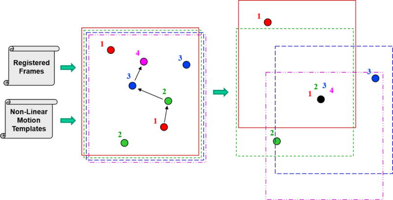
Visualization of the matched filter’s shift and stack process to co-locate a target for integration gain prior to threshold detection. The arrows indicate the shift vectors linking an asteroid position moving through the 4 frames. Other numbered points are spurious objects. The right side of the figure show the shifted frames with the desired object in the four frames aligned at one point (A color version of this figure is available in the online journal).
The heavy computational burden arises from the unknown nature of the starting position, angular speed of the NEO, and direction of motion which results in a large number of shift vector templates or motion hypotheses that need to be examined – each requiring a shift and stack operation. For a parallax inducing observation geometry, this is further compounded by the unknown range and the possible existence of range parallax for close NEOs. The net result is that there may easily be more than a million motion hypotheses that need to be examined to fully account for an NEO’s potential movement across the focal plane.
Considering the processing load expected due to parallax effects, an existing software package for asteroid detection has been successfully modified to utilize multiple-processors and/or GPUs to provide runtime enhancements. This was done while also tackling the non-linear motion behavior of the observed NEOs. The baseline details on the Software Algorithm Testbed for Asteroid Detection (SALTAD), which is a matched filter detector implementation for asteroids that exhibit very limited smear in each collected image, has been reported on before (Gural and Larsen, 2003; Gural, Larsen, and Gleason, 2005). Appendix A provides a quick look analysis of the performance of the SALTAD matched filtering package applied to a variety of existing asteroid survey data sets using the MF’s hypothesized motion template matching approach.
The problem of the non-linearity of the parallax motion was handled within SALTAD by externally generating motion templates rather than modifying the software’s internal hypothesis generator. By using a single generic template format and input interface, the sensor specific information and state vector information can be abstracted away from the detection software, making a matched filter application independent of sensor, platform, and observation geometry particulars.
The classic matched filter operates on each motion hypothesis independent from other hypotheses, thus it could be said to be an embarrassingly parallelizable algorithm. Therefore, the issue with the MF computational load of processing millions of parallax templates is handled by distributing the processing either across CPU cores, operating in a cluster environment, and/or utilizing GPUs. In practice, the matched filter algorithm lends itself very well to a GPU type environment for the following reasons:
The input bandwidth into the GPU is low as the multi-frame image set is pushed only once onto GPU texture memory for the entire motion hypothesis set. GPU texture memory provides the interpolation step of the matched filter’s shift-and-stack operation for “free” whenever a pixel value is called for that lies between array grid points (non-integer shifts in row or column), and the GPU does the graphical (bi-linear) interpolation on the fly as part of the fetch.
The hypothesis templates contain very low bandwidth data (series of shift vectors) that get pushed into the GPU. It is made up of only two times the number of frames in terms of floating point values for every matched filter template and thus this I/O represents a small fraction of time relative to the matched filter operations of shift, add, and threshold processing.
The binary detection threshold map is culled to just a short detection list through a fast culling operation implemented as an application on the GPU. A “compaction” kernel was used for collapsing the detection list. Keeping this process on the GPU helped to lower the final product transfer bandwidth, which otherwise would have been one full frame in size per hypothesis (as a binary yes/no array).
The resultant output detection list per single hypothesis is also very low bandwidth as it can be user limited to typically no more than 30 detections per motion hypothesis. The final output products from the GPU includes pixel location, maximum likelihood estimate, and variance per detection threshold crosser, which is returned to the CPU for final gathering, sorting, culling, and reporting of results.
Runtime tests on various GPUs have shown a twenty times runtime improvement over a single CPU processor for the MF. These and other software improvements to SALTAD resulted in a twelve-minute processing time for a one million sized set of parallax motion templates on a Tesla K80 GPU for a 1024 × 1024 quartet of images. The shift and stack runtime cost in floating point operations (FLOPS) for a square NxN pixel image, M frames, and T templates using binomial interpolation is 20 * N2 * M * T FLOPS.
A subset of the matched filtering algorithm referred to as synthetic tracking (Shao et al., 2014; Zhai et al., 2014; Heinze, Metchev, and Trollo, 2015) has recently been enabled with the advent of fast readout sensors and high performance computational capabilities. The methodology is to apply a matched filter shift and stack operation to a very large number of frames where collection constraints are employed to maximize the SNR of an object in each frame and avoid trailing losses. To do that, the collection integration time per frame is shortened to prevent the asteroid from smearing beyond one pixel. Thus an accompanying fast readout sensor must be employed, which results in a many-fold increase in frame count, but also results in matched filter SNR gains. Since synthetic tracking uses a matched filter shift and stack operation to obtain signal gain, the use of non-linear shift vectors in the templates fits naturally within the ST algorithm’s processing architecture. Therefore, parallax can be handled in the same way as in any matched filter approach.
5. Recommendations and Conclusions
The following salient points can be made on collection induced shift vectors, their non-linear behavior, and their impact on asteroid detection software. These apply equally well to both space-based imaging surveys and coordinated ground surveys from widely separated sites.
Both the matched filter and pattern matching techniques can be adapted to handle nonlinear motion hypotheses within the basic formalisms of those algorithms.
The detection processing module should be architected such that it is not dependent on imagery metadata by working with a generic shift vector template ingest interface and offloading the template generation to an application unique to each sensor platform.
Induced parallax motion templates have an enormously beneficial self-similarity property associated with asteroid velocity and range, allowing the simplifying concepts of a zero-motion template, range-bounding and velocity-bounding templates to be formulated.
For both matched filtering and synthetic tracking, it is paramount to minimize the hypothesis count and consider distributable computing architectures and/or GPUs to handle the added load of range hypotheses from parallax effects to the existing position, speed and direction hypotheses.
To address obtaining very rapid response answers for dynamic tasking and quick follow-up observations, one of the most computationally efficient algorithms is the classical pattern matching approach, even with non-linear shift vector templates.
The authors wish to acknowledge the collaborative support of the Canadian NEOSSat science team of Alan Hildebrand, Rob Cardinal, Brett Gladman, and Mike Mazur as well as U.S. science team participants Paul Chodas, Stephen Larson, and Mikael Gravnik for valuable and ongoing technical interchanges and discussions over the course of this project. This work was funded under NASA’s Lunar and Planetary Science U.S. Participating Investigator Program grant NNX09AM06G and Near-Earth Observations Program grant NNX16AK19G.
The matched filter, template generator, and pattern matcher software (SALTAD, TGEN, and PMATCH) can be obtained by filling out a Software User Agreement (SUA) and submitting it through NASA’s Office of Technology Transfer5 via their T2 Portal (search through the software catalog for SALTAD). Separately, these instructions, the SUA, and software documentation can be found on the NASA GitHub website6.
Appendix A. Application to Existing Survey Data Sets
To demonstrate the application of shift vector motion template formation, specifically for matched filter processing, the SALTAD application presented herein was used to process a wide variety of image sets from past asteroid surveys. These image sets were from ground-based surveys with little to no induced parallax, but the templates were formed accounting for motion of the telescope over the course of each collection frame set. The application employed a maximum likelihood estimate (MLE) metric for its multi-frame integrated detection criteria, set to 11.5 dB, i.e. approximately equivalent to SNR = 4 per frame. This MLE level resulted in a conservative false alarm rate of 3% across all candidate detections. All detections were reviewed by visual inspection and declared reliable by examining individual frames and concatenated multi-frame colorized snapshots, where the analyst could confidently declare visibility of the asteroid against the background and consistent object motion across all frames. Marginally visible and noise cases were rejected as false alarms. Thus, the software’s multi-frame candidate detections were considered very highly reliable and were likely main belt asteroids, as their motion was in the same general direction and speed as other previously known main belt asteroids in the field.
Table 3 presents the results for a limited set of imagery, using various collection sensors, systems, geometries, and cadences. In each case, the MF detection processing found the known asteroids in the field as previously reported by the surveys, plus additional moving objects. The repeatability with past NEO survey reporting demonstrates the reliability of motion template matching on actual asteroid survey data as applied in a MF processing scenario independent of imagery characteristics.
Many new potential Solar System objects were also found in addition to those previously reported by the surveys which used detect-before-track type algorithms. This is indicated by the tracklet yield enhancement column in Table 3. While this is not a rigorous validation of performance enhancement by the MF over frame-by-frame thresholding, it is consistent with reported results in the footnotes of Table 3 as well as those obtained using synthetic tracking methods, which are also based on matched filter processing (Shao et al., 2014; Zhai et al., 2014; Heinze, Metchev, and Trollo, 2015). Thus, other previous surveys could benefit from data mining using the matched filter algorithm discussed herein, and in situations that may arise in the future where parallax shift vectors will be required.
Detailed notes with respect to the survey processing in Table 3:
WISE is a space based infrared imaging sensor that has been used for asteroid searches at a wavelength of 12 microns (WISE band 3). However, due to the nature of the observation geometry, where the satellite is over the same geographic latitude for a given space pointing direction, asteroids appear to move in linear paths across the focal plane with no parallax evident in the observations examined. Thus, for the limited data sets downloaded for WISE, the spacecraft’s imagery could not be used as a surrogate space-borne platform for testing parallax detection performance.
The CSS-II image processing pipeline currently in use is very effective at detecting asteroids and performs comparably to the MF processing approach with the MF showing virtually no gain in yield. For example, using the Schmidt telescope (CSS-II 703) quartet observation images provided by Larson (2017, personal communication), the column labeled “MF found” gives two numbers. The 261 detections are for the MF having equivalent numbers of 23 false alarms as the CSS survey pipeline. Whereas the 293 detections are for the MF with a much higher number of 184 false alarms, as it probed deeper into the noise. Clearly there is not much to be gained over the existing CSS processing method without incurring additional false alarms to be reviewed by a human-in-the-loop after initial detection processing. A tolerance level that each survey has to set, and one that will likely vary depending on the image quality.
Wall-clock runtime on the largest image set from the sample in Table 3 (a registered 4080 × 4080 pixel NEAT image) using a PC with an Intel Core i7 5930K 3.5GHz CPU and an NVIDIA GeForce Titan X Maxwell GPU was ~5.5 minutes.
Table 3.
Comparison of MF Enhancement in High Confidence Tracklet Yields for Various Surveys
| Survey | Observation Date | Survey Found | MF Found | Yield Enhancement (%) | |
|---|---|---|---|---|---|
| Spacewatcha | 2000-02-04 | 1 triplet | 950 | 1380 | 45% |
| NEATb | 1997-12-29/30 | 2 full nights | 744 | 949 | 27% |
| WISE Band 3c | 2010-03-15 | 2 triplets | 6 | 7 | 17%e |
| CSS-II G96 1.5md | 2017-02-22 | 1 quartet | 245 | 247 | 1 % |
| CSS-II 703 68cmd | 2017-03-02 | 1 quartet | 273 | 261 - 293 | 0 - 7% |
NASA PDS7;
NASA IRSA8;
Larson (2017, personal communication).
Cf., Mazur, Hildebrand, and Gural (2018) who found 20% more real detections using the same software.
Footnotes
References
- Bernstein G, Trilling D, Allen R, et al. AJ. 2004;128:1364. [Google Scholar]
- Bertin E, Arnouts S. A&AS. 1996;317:393. [Google Scholar]
- Denneau L, Jedicke R, Grav T, et al. PASP. 2013;125:357. [Google Scholar]
- Dawson W, Schneider M, Kamath C. (Report LLNL-CONF-703048).Proceedings of the Advanced Maui Optical and Space Surveillance Technologies Conference September 20-23, 2016. 2016 [Google Scholar]
- Evans RW, Stapelfeldt KR, Peters DP, et al. Icarus. 1998;131:261. [Google Scholar]
- Franz M, Harper D. P&SS. 2002;50:217. [Google Scholar]
- Gural P. Proceedings of the International Meteor Conference. 2016:96. [Google Scholar]
- Gural PS, Larsen J. (NTIS Issue Number 200415).Technical Report. 2003 [Google Scholar]
- Gural PS, Larsen J, Gleason A. AJ. 2005;130:1951. [Google Scholar]
- Hapgood MA. P&SS. 1992;40:711. [Google Scholar]
- Heinze A, Metchev S, Trollo J. AJ. 2015;150:125. [Google Scholar]
- Hildebrand AR, Tedesco EF, Carroll KA, et al. LPI. 2007;1338:2372. [Google Scholar]
- Kubica J, Denneau L, Grav T, et al. Icarus. 2007;189:151. [Google Scholar]
- Mazur MJ, Hildebrand AR, Gural PS. LPI. 2018;2083:2242. (Published online but not yet in the ADS database.) [Google Scholar]
- Mohanty NC. ITPAM. 1981;3:606. doi: 10.1109/tpami.1981.4767153. [DOI] [PubMed] [Google Scholar]
- Parker A, Kavelaars J. PASP. 2010;122:549. [Google Scholar]
- Pohlig SC. ITAES. 1995;31:608. [Google Scholar]
- Reed I, Gagliardi R, Shoa H. ITAES. 1983;19:898. [Google Scholar]
- Sanders JN. Lincoln Labs Technical Report. 1992:946. [Google Scholar]
- Sanders-Reed JN. ITAES. 1998;34:844. [Google Scholar]
- Shao M, Nemati B, Zhai C, et al. ApJ. 2014;782:1. [Google Scholar]
- Shucker BD, Stuart JS. ACM. 2008;8388 [Google Scholar]
- Stokes G, Evans J, Viggh H, et al. Icarus. 2000;148:21. [Google Scholar]
- Zhai C, Shao M, Nemati B, et al. ApJ. 2014;792:60. [Google Scholar]