Abstract
A low-cost sulfonated polysulfone (SPSU)/poly(vinyl chloride) (PVC) substrate based high-performance thin-film composite (TFC) forward osmosis (FO) membrane was fabricated in this work. The results showed that the morphologies of the substrates were looser and more porous, and the porosity, pure water permeability, surface hydrophilicity, and average pore size of the substrates significantly improved after the SPSU was introduced into the PVC substrates. Furthermore, the SPSU/PVC-based TFC membranes exhibited rougher, looser and less crosslinked polyamide active layers than the neat PVC-based TFC membrane. The water permeability obviously increased, and the structure parameter dramatically declined. Moreover, the FO performance significantly improved (e.g. the water flux of TFC2.5 reached 25.53/48.37 LMH under FO/PRO mode by using 1.0 M NaCl/DI water as the draw/feed solution, while the specific salt flux exhibited a low value of 0.10/0.09 g/L). According to the results, it can be concluded that 2.5% of SPSU was the optimal blend ratio, which exhibited the lowest sulfonated material blend ratio compared to the data reported in the literature. Hence, this is a feasible and low-cost fabrication approach for high-performance FO membrane by using the cheap PVC and low blend-ratio SPSU as the membrane materials.
Introduction
Forward osmosis (FO) has attracted the attention of researchers as an energy-efficient membrane technology in recent years1–4. Without requiring a high hydraulic pressure, FO utilizes osmotic pressure differences to drive the water across the FO membrane from a low-osmotic-pressure feed solution to a high-osmotic-pressure draw solution2. Hence, compared to traditional pressure-driven separation technologies, such as reverse osmosis (RO) and nanofiltration (NF), FO has several merits, including: 1) lower energy consumption and equipment costs; 2) less membrane fouling; 3) higher water recovery; and 4) wider applications5–8. However, FO membranes have a critical problem, internal concentration polarization (ICP). The ICP can be ascribed to the resistance to diffusion of the FO membranes, which leads to a reduction in the osmotic pressure across the membrane9. Compared to the external concentration polarization (ECP), which occurs outside the FO membranes, the ICP resides in the membranes, which means that it cannot be alleviated by hydrodynamics optimization9. Hence, FO membrane fabrication optimization is a practical method to relieve the ICP.
Fabrication of high-performance FO membranes is a research hotspot in the FO field10–13. An ideal FO membrane should have a high water flux and limited reverse salt flux during a FO process14. Generally, FO membranes can be divided into three types: (1) asymmetric membranes15,16; (2) layer-by-layer self-assembled membranes17,18; and (3) thin-film composite (TFC) membrane8–11. Because of their good FO performance and wide pH application range, TFC FO membranes have gained the most attention from FO researchers. The TFC FO membrane consists of a porous substrate layer and an ultra-thin active layer19. Moreover, the substrate plays an important role in the performance of FO membranes. Hence, most researchers of TFC FO membranes focus on substrate studies. Polysulfone (PSU), polyethersulfone (PES) and polyvinylidene fluoride (PVDF) are the most popular backbone materials for preparing the substrates for TFC FO membranes3. However, these materials are hydrophobic polymers. Hence, the hydrophilicity of the substrate needs to be improved to decrease the ICP and improve the performance. Introduction of hydrophilic polymers and nanoparticles into substrates are the feasible strategies3,14. For instance, Zhou et al.9 modified a PSU substrate by blending it with sulfonated poly(phenylene oxide) (SPPO). Their work demonstrated that the introduction of SPPO significantly improved the performance of the TFC FO membrane. Emadzadeh et al.19 introduced TiO2 nanoparticles into the substrate. Their results illustrated that the porosity and hydrophilicity obviously improved after the modification, which led to a considerable remission of the ICP. Wang and Xu12 blended PES, sulfonated polyethersulfone (SPES) and montmorillonite to fabricate the substrate. Their results illustrated that montmorillonite could anchor the SPES in the substrate to improve the FO performance.
Generally, backbone materials and hydrophilic modifiers contribute to the costs of membranes20,21. The widely used backbone materials (e.g. PSU, PES and PVDF) are not low-cost products, and the modifier materials are even more expensive or lab-made products. Hence, the manufacturing costs of FO membranes are an obstacle for the application of the FO technology. Using a low-cost backbone material and reducing modifier use could lower the manufacturing costs. Poly(vinyl chloride) (PVC), which is one of the most widely-used and low-cost resins (<1/10 price of PSU, PES, or PVDF), exhibits excellent characteristics of acid and alkali resistance, abrasion resistance and good mechanical strength20. Moreover, PVC can be dissolved in various industrial solvents22. Hence, PVC can be applied for the fabrication of membranes via the nonsolvent-induce phase separation (NIPS) process20,22–24. However, due to its inherent hydrophobicity, hydrophilic modification is necessary for fabricating PVC membranes. On the other hand, sulfonated polymers, such as SPPO9, SPES12, sulfonated polysulfone (SPSU)25, sulfonated poly(ether ketone) (SPEK)26, disulfonated poly(arylene ether sulfone) (DSPAES)27, and polyethersulfone and sulfonated polyphenylsulfone copolymer (PES-co-SPPSU)28, are widely used to improve the hydrophilicity of membranes. However, a high blend ratio of the sulfonated polymers is unfavorable for cost control. Hence, a reasonable blend ratio of sulfonated polymers should be required and studied.
This work aims to fabricate a high-performance TFC FO membrane with low manufacturing costs. Therefore, PVC was chosen as the low-cost backbone material and SPSU as the hydrophilic modifier material for preparation of the substrates for the TFC FO membranes in this study. The SPSU/PVC substrates were first prepared for fabrication of the TFC FO membranes. The characteristics and performances of a series of SPSU/PVC substrates were fully investigated, including the morphology (by SEM study), porosity, pure water permeability (PWP), surface hydrophilicity (by contact angle), and average pore size. Moreover, the effect of the properties of the SPSU/PVC substrates on the morphology and intrinsic properties of the TFC FO membranes was investigated. Finally, the optimal blend ratio of SPSU and PVC was determined through the intrinsic properties and FO performance of the TFC membranes.
Materials and Methods
Chemicals and membrane materials
PVC (P440, k-value of 73–75, Shenfeng Chemicals Co. Ltd., China) and SPSU (sulfonation degree = 20%, Shanghai Yunli Polymer Co. Ltd., China) were used as the materials for preparation of the substrates. 1-Methyl-2-pyrrolidinone (NMP, >99.5%, Aladdin) was used as the solvent for preparation of the casting solutions. M-phenylenediamine (MPD, >99%, Sigma-Aldrich), trimesoyl chloride (TMC, >98%, Sigma-Aldrich) and n-hexane (>99%, Aladdin) with were used for the interfacial polymerization (IP) process. Sodium chloride (NaCl, >99.5%, Aladdin) was used as the draw solute.
Fabrication of flat-sheet TFC FO membranes
Preparation of blended substrates via phase inversion
The preparation of the SPSU/PVC substrates was based on the NIPS process. The casting solution compositions are provided in Table 1. PVC and SPSU were dissolved in NMP and continuously stirred at 60 °C for 24 h to obtain a homogeneous and transparent solution. After degassing at room temperature for 24 h, the casting solution was cast on a pre-cleaned glass plate using a 150 μm stainless-steel casting knife. After evaporation in a fume hood for 30 s, the as-cast substrates with the glass plate were immersed into a deionized (DI) water coagulation bath at the ambient temperature to initiate the phase inversion. Afterwards, the obtained substrates were transferred into a flowing DI water bath for 48 h to remove residual solvent before further use.
Table 1.
Composition of the casting solutions for the preparation of the blended substrates.
| Membranes | Total polymers (wt%) | PVC (wt%) | SPSU (wt%) | NMP (wt%) | m(SPSU):m(PVC) |
|---|---|---|---|---|---|
| S0 | 15 | 15.000 | 0.000 | 85 | 0.0: 100.0 |
| S0.5 | 15 | 14.925 | 0.075 | 85 | 0.5: 99.5 |
| S1 | 15 | 14.850 | 0.150 | 85 | 1.0: 99.0 |
| S2.5 | 15 | 14.625 | 0.375 | 85 | 2.5: 97.5 |
| S5 | 15 | 14.250 | 0.750 | 85 | 5.0: 95.0 |
| S10 | 15 | 13.500 | 1.500 | 85 | 10.0: 90.0 |
Preparation of the polyamide active layer
The polyamide (PA) active layer was prepared with MPD and TMC monomers via an interfacial polymerization (IP) process on the surface of a neat PVC or SPSU/PVC substrate. First, the prepared substrate was immersed in an aqueous solution of 2.0 wt.% for 120 s. The excess MPD solution was removed by pure compressed nitrogen gas for 2 min. Then, a 0.1 wt.% n-hexane solution of TMC was gently poured onto the MPD-soaked substrate surface to form the PA layer for 60 s. After the n-hexane solution was drained off, the nascent TFC membrane was air-cured for 5 min. The resultant TFC membrane was rinsed with DI water to remove the residual monomers and then stored in DI water before characterization and performance testing. These membranes are denoted as TFC0, TFC0.5, TFC1, TFC2.5, TFC5, and TFC10 according to the label names of the substrates.
Light transmittance experiment
Light transmittance experiments were performed using a self-made device, and more details were provided in Yu’s study29. The casting solution was cast on a glass plate with the same procedure of preparation of the substrates. The glass plate was immersed into the DI water bath used as the coagulation fluid. The light source was directly above the casting solution, approximately 30 cm. An optical detector (DT1309, Huashengchang, China) was used to detect the transmitted light, and the detected data were recorded by a computer.
Membrane characterization
Morphology of the substrates and active layer
The morphology of the substrate and active layer was observed with a high-resolution field emission scanning electron microscope (HR-FESEM, Merlin, Carl Zeiss, Germany). The samples of the substrates and TFC FO membranes were first freeze dried for 48 h. The samples were coated with platinum by a sputtering coater (150 T, EMS, UK). The samples were flash-frozen and cracked in liquid nitrogen for observation of the cross-section before freeze drying.
Properties of the substrates and active layer
The PWP of the substrates was determined in a lab-scale cross-flow filtration device, which gives an effective membrane area of 11.34 cm2. All substrates were pre-compacted at 1.5 bar for 60 min to obtain a steady flux. The PWP data were tested at 1.0 bar after the pre-compaction.
The porosity (ε) of the substrate was based on the difference between the wet and dry weights of the substrate sample by Eq. (1), where m1, m2, ρ, T and Am represent the wet weight, dry weight, the density of DI water, thickness and effective area of the substrate sample, respectively.
| 1 |
The average pore size (rm) was calculated based on the PWP and porosity data by using the Gerout-Elford-Ferry equation (Eq. (2)), where η and T represent the viscosity of DI water and thickness of the substrate sample, respectively.
| 2 |
The contact angle of the substrate was measured by a contact angle goniometer (DSA25, Kruss, Germany). Droplets of DI water (2 μL) were applied onto a pre-dried substrate surface to test the contact angle. Five measurements were carried out at random locations on a substrate sample.
The chemical composition of the polyamide active layer was analyzed by X-ray photoelectron spectroscopy(XPS, Escalab 250xi, Thermo Fisher Scientific, UK) using a monochromatic Al X-ray source.
Intrinsic properties of the TFC membrane
The water permeability (A) and salt permeability (B) were determined in the same filtration device applied to test the PWP of the substrates. The A value was measured using DI water as the feed solution under a pressure of 5.0 bar. The A value was calculated using Eq. (3), where ΔVa is the permeate volume in the water permeability test over a fixed time Δta, Am is the effective area of the TFC membrane, and ΔP is the transmembrane pressure difference.
| 3 |
The salt permeability (B) was calculated based on the salt rejection (Rs) and A value19. The Rs value was measured by using a 2000 ppm NaCl solution as the feed solution under a pressure of 5.0 bar. The Rs and B values were calculated by Eqs (4) and (5), respectively, where Cf and Cp are the NaCl concentrations of the feed and permeate solutions and ΔP and Δπ are the transmembrane hydraulic and osmotic pressure differences, respectively.
| 4 |
| 5 |
The structure parameter (S) can be estimated by the classical flux-fitting method with Eq. (6)30,31, where D is the solute diffusion coefficient, πdraw and πfeed are the osmotic pressures of the draw solution and feed solution, respectively, and JW is the water flux under FO mode in the performance test which would be discussed in section of FO performance tests.
| 6 |
FO performance tests
The FO performance was evaluated on a lab-scale cross-flow filtration setup with an effective membrane area of 12 cm2 (2 cm × 6 cm). The feed and draw solutions were circulated co-currently through rectangular channels at a fixed crossflow rate of 480 mL/min. The DI water and NaCl solution were used as feed and draw solutions, respectively. The weight changes in the NaCl solution were recorded by a data-logging balance (AX4202ZH, Ohaus, USA) to reflect the water flux (JW), and the NaCl concentration changes in the feed solution were recorded by a conductivity meter (DDSJ-308F, Rex, China) to reflect the reverse salt flux (JS). All of the FO performance tests were carried out for 75 min, and the JW and JS values were calculated by the average of the data from the last 60 min. Particularly, the FO performance was tested under two operation modes, namely, FO mode, where the active layer faced the feed solution, and PRO (pressure-retarded osmosis) mode, where the active layer faced the draw solution.
The JW and JS values were calculated by Eqs (7) and (8), where ΔV is the volume change of the DS over a fixed time (Δt), Sm is the effective area of the TFC membrane, Ct and C0 are the initial and final concentrations of the feed solution, respectively, and Vt and V0 are the initial and final volumes of the feed solution.
| 7 |
| 8 |
Data availability statement
The data of this study are available from the corresponding author on reasonable request.
Results and Discussion
Phase inversion properties
Light transmission experiments were carried out to illustrate the effect of the blend ratios of SPSU and PVC on the phase inversion mechanism of the substrates. The phase inversion process will lead to the optical inhomogeneity of the casting solution and decrease the light transmittance. Therefore, the decreasing rate of light transmittance can be used to represent the rate of the phase inversion process32. Figure 1 shows the results of the light transmission experiments. The phase inversion speed became slower after SPSU was introduced into the casting solution. This phenomenon may arise from the presence of sulfonic acid groups in SPSU, which can form hydrogen bonds with water molecules. Hydrogen bonding can enhance the water tolerance of the SPSU-introduced casting solutions and delay the solvent (NMP) and the non-solvent (water) exchange33. Obviously, the introduction of SPSU affected the phase inversion process, which will have an important effect on the morphology and performance of the prepared substrates.
Figure 1.
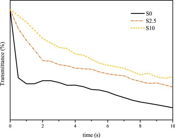
Light transmission test of the casting solution.
Characteristics and performances of the substrates
Morphology of the substrates
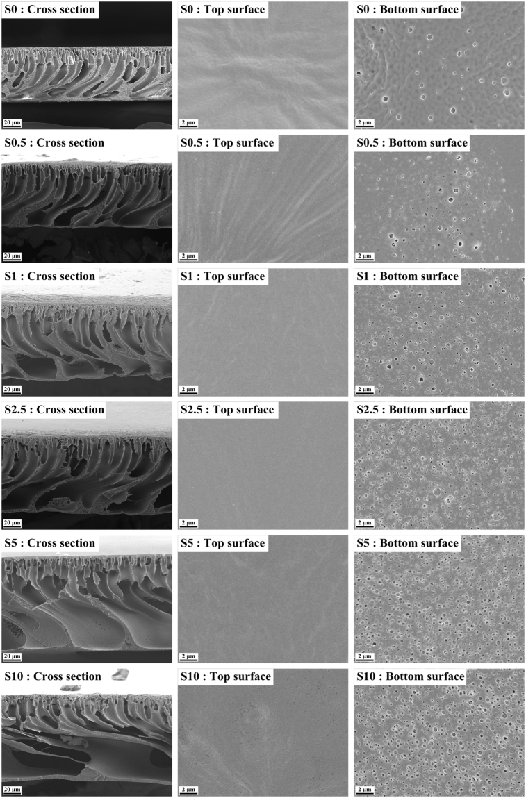
Figure 2 shows the FESEM images of the cross-sections, top surfaces, and bottom surfaces of the substrates. According to the cross-section images, all the substrates exhibited typical asymmetric morphologies. However, the increasing SPSU/PVC blend ratio led to a noticeable difference in the morphology of the substrates. For the neat PVC substrate, numerous “lanky” finger-like pores were separated by a the sponge-like medium in between. After the SPSU was introduced into the substrates, the finger-like pores became larger and more irregular significantly. Eventually, the pores became interconnected near the bottom part of the substrates at the SPSU/PVC blend ratio of 10%. This means that the SPSU is beneficial for improving the porosity of the substrates, which would be confirmed by the porosity test results. This morphology change should come from the slower phase inversion speed. According to Blanco’s theory34, the slower the phase inversion rate, the more developed the polymer-lean phase growth and coalescence, resulting in the larger finger-like pores, and a similar phenomenon was found in Ren’s research33. It is believed that the looser and more porous substrates could conduce to decline the ICP in the FO process19. Moreover, it can be seen in the cross-section images that the thicknesses of the substrates increased after the SPSU was introduced, and the increment of the thickness should be related to the increase in the thermodynamics instability caused by SPSU35. Similar phenomena were found in Ou36 and Wang’s12 works.
Figure 2.
FESEM images of the substrates with different SPSU/PVC blend ratio.
According to Fig. 2, the top surface images exhibited few differences for all substrates. All the top surfaces exhibited dense surface morphologies with a few small pores. However, compared to the top surfaces, the bottom surfaces of all the substrates exhibited more open and porous morphologies with larger pores. Along with the increase in the SPSU/PVC blend ratios, the bottom surfaces became significantly more porous. The more open bottom morphology could accelerate the salt diffusion from the draw solution into the substrate (under FO mode) to alleviate the dilutive ICP, or from the substrate to the feed solution (under PRO mode) to alleviate the concentrative ICP9.
Properties of the substrates
Table 2 summarizes the properties of the substrates prepared with different SPSU/PVC blend ratios. The hydrophilicity of the substrates was illustrated by contact angel tests. The contact angle value declined from 84.9° for S0 to 75.5° for S10. This result indicates that the introduction of SPSU enhanced the hydrophilicity of the substrates significantly due to the presence of the sulfonic acid groups on the SPSU. Moreover, the overall porosity (ε) and the mean pore size (rm) increased with the increase in the SPSU/PVC ratio. The major reason of this phenomenon can be ascribed to the larger size of the finger-like pores caused by the lower phase inversion rate33,34. An obvious improvement in the porosity of the S0.5 (86.0%) was observed compared to that of S0 (81.1%). Moreover, the porosity slightly improved to 90.2% for S10. It is believed that the higher value of the porosity is the main factor contributing the smaller structure parameter (S value) of the substrate, which leads to a smaller ICP during a FO process19. Furthermore, the PWP got obviously improved after the SPSU was introduced. According to the Hagen-Poiseuille pore flow model, the increasing mean pore size and porosity should be ascribed to a crucial factor in the improvement of the PWP37. The hydrophilicity of the SPSU could improve the water permeability by drawing water molecules into the substrate and facilitating their transportation throughout the substrate36.
Table 2.
Summary of the SPSU/PVC substrates characteristics.
| Membranes | ε (%) | PWP (LHM/bar) | Contact angle (°) | rm (nm) |
|---|---|---|---|---|
| S0 | 81.1 ± 0.6 | 54.1 ± 4.2 | 84.9 ± 0.8 | 12.8 ± 0.8 |
| S0.5 | 86.0 ± 0.2 | 77.7 ± 1.6 | 79.9 ± 1.6 | 15.1 ± 0.3 |
| S1 | 87.7 ± 0.1 | 121.3 ± 8.4 | 78.2 ± 1.2 | 20.2 ± 0.9 |
| S2.5 | 89.1 ± 0.4 | 208.8 ± 11.0 | 77.1 ± 1.2 | 26.6 ± 0.5 |
| S5 | 89.5 ± 0.3 | 315.5 ± 25.1 | 76.7 ± 2.1 | 34.4 ± 1.5 |
| S10 | 90.2 ± 0.2 | 395.5 ± 32.5 | 75.5 ± 2.7 | 37.9 ± 0.1 |
Characteristics and performances of the TFC membranes
Morphology and properties of the active layer of the TFC membrane
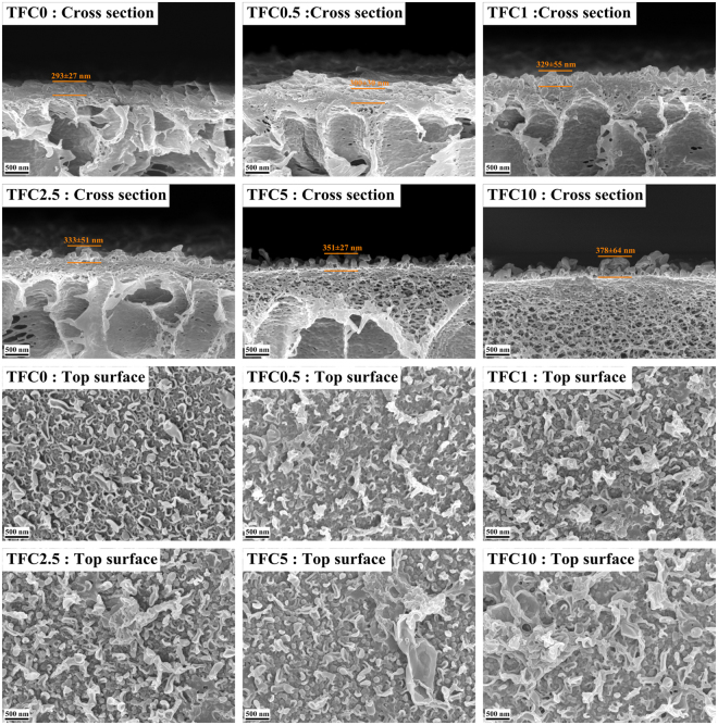
The polyamide active layer was synthesized on the substrates via an interfacial polymerization reaction between TMC and MPD at the oil-water interface. FESEM images (Fig. 3) were used to illustrate the morphological changes in the active layers of the TFC membranes. According to the top surface images, all the active layers of the TFC membranes exhibited a typical ridge-and-valley morphology. However, there are obvious differences between the neat PVC-based and SPSU/PVC-based TFC membranes. The top surface of TFC0 exhibited a smoother, nodular-like structure. The top surface of the SPSU/PVC based TFC membranes had rougher, grass-like structures, and more open top surface structures were observed as the SPSU blend ratio increased. The pore size difference may be the major factor resulting from this phenomenon. During the interfacial polymerization, MPD molecules migrated to the oil-water interface via diffusion and simple convection on substrates with smaller pore size. In contrast, this migration is dominated by the more vigorous Marangoni convection rather than diffusion and simple convection. The Marangoni convection results in a turbulent flow, enlarge the reaction contact area and may even push around, rotate, twist and bend the early-formed polyamide domains8,38. Hence, the polyamide active layer formed on the substrates with larger pores would exhibit a rougher and more open structure. Meanwhile, according to the images of the cross-sections, the thickness increased with the SPSU ratio. This phenomenon is probably because the SPSU-blended substrates with a higher porosity can hold more MPD solution to react with the TMC molecules. Consequently, the TFC membranes based higher SPSU ratio substrates exhibited thicker polyamide active layers26. In addition, since the substrates a higher SPSU ratio can hold more MPD solution, the water molecules could compete with the MPD to react with the TMC molecules, resulting in a less crosslinked polyamide structure. This theory was confirmed by the following XPS tests.
Figure 3.
FESEM images of the active layers of different TFC membranes.
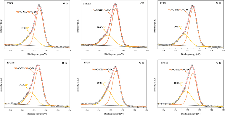
The chemical composition of the polyamide active layer was analyzed by the low-resolution XPS tests, and the results are exhibited in Fig. 4 and Table 3. According to Table 3, the oxygen atom composition increased with the increase in the SPSU ratio, and the nitrogen atom composition showed the opposite trend, which led to an obviously increased O/N ratio. The increased O/N ratio illustrates that the crosslinking degree of the active layer declined with an increase in the SPSU ratio39. Furthermore, high-resolution XPS tests were carried out to determine changes in the functional groups on the active layer surfaces, especially carboxyl groups; the results are shown in Fig. 5 and Table 4. The curve of the O 1 s spectrum could be resolved into two peaks at binding energies of 531.1 and 532.5 eV, which represent two existing states of oxygen. As shown in Fig. 5, one is HN-C=O* and O-C=O* (OI, 531.1 eV), and the other is *O-C=O (OII, 532.5 eV). The intensity ratios of IOI/IOII can be used to estimate the reduction degree of the carboxyl groups39. According to Table 4, the ratio of IOI/IOII decreased with increasing SPSU, which illustrates that more carboxyl groups were formed from the acyl chloride groups on the active layer.
Figure 4.
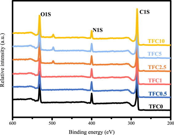
Low-resolution XPS spectra of the active layers in different TFC membranes.
Table 3.
Surface elemental composition of the active layers in different TFC membranes.
| Membranes | C | N | O | O/N |
|---|---|---|---|---|
| TFC0 | 73.31 | 12.09 | 14.60 | 1.21 |
| TFC0.5 | 73.94 | 10.98 | 15.08 | 1.37 |
| TFC1 | 73.37 | 10.76 | 15.87 | 1.47 |
| TFC2.5 | 73.00 | 10.55 | 16.44 | 1.56 |
| TFC5 | 72.20 | 9.94 | 17.87 | 1.80 |
| TFC10 | 72.49 | 9.48 | 18.03 | 1.90 |
Figure 5.
High-resolution XPS O 1 s spectra of the active layers in different TFC membranes.
Table 4.
Surface chemical composition of the active layers in different TFC membranes by XPS O 1 s spectral analysis.
| Membranes | OI | OII | OI/OII |
|---|---|---|---|
| TFC0 | 53,204.92 | 20,627.32 | 2.58 |
| TFC0.5 | 54,435.55 | 21,724.29 | 2.51 |
| TFC1 | 55,050.29 | 22,332.47 | 2.47 |
| TFC2.5 | 57,721.78 | 24,354.10 | 2.37 |
| TFC5 | 57,969.02 | 30,565.92 | 1.90 |
| TFC10 | 53,865.64 | 34,567.34 | 1.56 |
Intrinsic properties of the TFC membrane
Table 5 compares the intrinsic transport properties of the TFC membranes. The pure water permeability (A) exhibited an obvious augmentation after SPSU was introduced. Compared to the low A value of 0.67 LHM/bar for TFC0, the A value of the TFC2.5 showed a 231.34% improvement. Hence, with respect to the A value, SPSU played a considerable role in enhancing the TFC membrane performance. This improvement can be explained by the fact that the active layer became looser and less crosslinked after the SPSU was blended into the substrates. For same reason, the NaCl rejection rate (R) decreased with the increase of the SPSU blend ratio. However, according to the results, the R value decreased slightly from 96.01% for TFC0 to 95.12% for TFC2.5, and then decline obviously to 89.85%. Furthermore, the salt permeability (B) showed a more significant increase than A value. According to Eq. (5), the salt permeability (B) is positive correlation with the A value, and negative correlation with the R value. Hence, the B value should increase more significantly while A value increases and R decreases at the same time.
Table 5.
Intrinsic properties of the TFC membranes.
| Membranes | A a | R (%) | Bb (×10−8 m/s) | Sc (μm) | |
|---|---|---|---|---|---|
| LMH/bar | ×10−12 m/s Pa | ||||
| TFC0 | 0.67 ± 0.07 | 1.86 ± 0.21 | 96.01 ± 0.26 | 2.68 ± 1.74 | 2668 ± 147 |
| TFC0.5 | 1.29 ± 0.13 | 3.58 ± 0.36 | 95.40 ± 0.33 | 6.03 ± 0.58 | 823 ± 50 |
| TFC1 | 1.76 ± 0.18 | 4.89 ± 0.49 | 95.32 ± 0.32 | 8.40 ± 1.09 | 427 ± 29 |
| TFC2.5 | 2.54 ± 0.22 | 7.06 ± 0.62 | 95.12 ± 0.96 | 12.64 ± 2.45 | 337 ± 19 |
| TFC5 | 2.71 ± 0.10 | 7.53 ± 0.29 | 93.27 ± 1.06 | 19.10 ± 3.77 | 313 ± 7 |
| TFC10 | 2.80 ± 0.26 | 7.78 ± 0.72 | 89.85 ± 0.43 | 30.85 ± 4.38 | 286 ± 16 |
aA values were measured in RO testing mode at 5.0 bar pressure with DI water as the feed solution.
bB values were measured in RO testing mode at 5.0 bar pressure with 2000 ppm NaCl as the feed solution.
cS values were measured under FO mode using 1 M NaCl as the draw solution and DI water as the feed solution.
The structure parameter (S) can be expressed as the diffusion distance for solutes to cross the substrate layer and is used as a metric to evaluate the ICP in the FO process30. Generally, a smaller S value indicates a lower level of ICP9,40. As shown in Table 3, the S value for TFC0 exhibited an extremely high value of 2668 μm, which indicates that the neat PVC substrate is not suitable for the preparation of a high-performance TFC FO membrane. However, the S values declined sharply after SPSU was introduced into the substrates. The S values decreased to 337 μm for TFC2.5, and 286 μm for TFC10 lastly.
Performance of the TFC FO membranes
The performance of the TFC FO membranes prepared by different substrates was assessed under both FO and PRO modes using 1 M NaCl as the draw solution and DI water as the feed solution. The water flux, reverse salt flux and specific salt flux are shown in Fig. 6.
Figure 6.
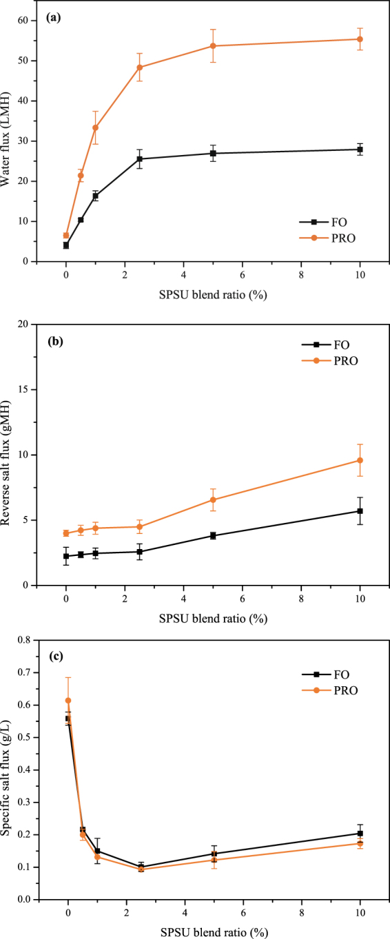
FO performance of the TFC FO membranes based on different substrates: (a) water flux, (b) reverse salt flux, and (c) specific salt flux.
Figure 6(a) shows the water flux of the TFC membranes prepared from different substrates. Consistent with most prior works33,37,41, higher water fluxes were observed under the PRO mode than the FO mode for all TFC membranes. This phenomenon can be explained by the fact that a more severe dilutive ICP would reduce the osmotic driving force across the FO membrane and decrease the water flux in the FO mode, while a slightly concentrative ICP occurs in the PRO mode41. After SPSU was introduced into the substrates, the water fluxes significantly improved. As it can be seen from Fig. 6(a), the water flux was remarkably improved from 4.02 LMH for TFC0 to 25.53 LMH for TFC2.5 under the FO mode, and from 6.50 LMH for TFC0 to 48.37 LMH for TFC0 under the PRO mode. This phenomenon can be attributed to the thinner and looser active layer and lower S value, which lead to a higher water permeability and lower ICP40. However, the improvement in the water flux was limited when the SPSU blend ratio was above 2.5%.
The reverse salt flux results under different modes are shown in Fig. 6(b). The trend of the reverse salt flux is consistent with that of the R data in the membrane intrinsic properties tests. The reverse salt fluxes slightly improved from 2.25 gMH for TFC0 to 2.57 gMH for TFC2.5 under the FO mode, and from 3.99 gMH for TFC0 to 4.50 gMH for TFC2.5 under the PRO mode. Then, the reverse salt fluxes obviously improved to 5.71 gMH for TFC10 under the FO mode, and to 9.59 gMH for TFC10 under the PRO mode. This phenomenon can be attributed to that the less crosslinked polyamide active layer would reducing the salt rejection efficiency and increasing the reverse salt flux19.
The specific salt flux (reverse salt flux/water flux ratio) is considered an explicit performance metric that can be used to assess the osmotic process efficiency and compare membrane performances of different membranes. A high-performance FO membrane requires a high water flux and low reverse salt flux; thus, a membrane with a low specific salt flux is preferred30. As can be seen in Fig. 6(c), the specific salt flux declined significantly after SPSU was introduced into the substrates and reached the minimum of 0.10/0.09 g/L (FO/PRO mode). Moreover, because of the increase in the reverse salt flux, the specific salt flux slightly increased when the SPSU blend ratio was above 2.5%.
Figure 7 exhibits the water fluxes results for TFC0 and TFC2.5 under both FO and PRO modes as a function of the draw solution concentration. The overall water flux increased with the draw solution concentration. However, the water fluxes of TFC2.5 increased more significantly than that of TFC0. According to the data, the water flux of TFC2.5 increased 67.01%/73.12% from 0.5 M to 2.0 M NaCl draw solution under FO/PRO mode, while the water flux of TFC0 increased only 19.84%/21.07%. This significant difference between the neat PVC-based and SPSU/PVC-based TFC membranes could illustrate that the introduction of SPSU could obviously reduce the ICP during the FO process27,37.
Figure 7.
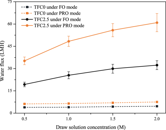
Water flux of TFC0 and TFC2.5 for various draw solution concentrations using DI water as the feed solution.
Performance comparison with other sulfonated materials based TFC membranes
It is believed that blending a sulfonated polymer with a backbone polymer to fabricate a substrate is a feasible strategy for improving the performance of a TFC FO membrane9,25–28,33. Table 6 and Fig. 8 compare the FO performances of the different sulfonated polymers-based TFC FO membranes in this work and those published in the literature. All of the TFC FO membranes were tested under the FO mode by using 1 M NaCl and DI water as the draw solution and feed solution. Compared to other sulfonated polymer based TFC membranes, the TFC2.5 with the lowest sulfonated blend ratio exhibited an excellent performance, while the other TFC membranes reported in the literature required blends above 12.5% sulfonated polymers (even 50%) to obtain the same-level water flux. Generally, sulfonated polymers are more expensive than the backbone polymers in material markets. A lower sulfonated blend ratio can reduce the manufacturing cost of fabrication the TFC membranes. Figure 6 plots both the specific salt flux and water flux of these TFC membranes. A superior performance for both the specific salt flux and water flux is presented in the top right corner. According to Fig. 8, the FO performance was significantly improved after SPSU was introduced into the substrates and was optimized at a sulfonated blend ratio of 2.5%. Moreover, the TFC2.5 exhibited a better performance than other sulfonated polymers-based TFC membranes in the reported literature.
Table 6.
Comparison of the performances of the TFC membranes in this work and those reported in the literature.
| NO. | Backbone polymer | Sulfonated polymer | Blend ratio | JW (LMH) | JS (gMH) | JS/JW (g/L) | Reference |
|---|---|---|---|---|---|---|---|
| TFC0 | PVC | — | 0% | 4.02 | 2.25 | 0.56 | This work |
| TFC2.5 | PVC | SPSU | 2.5% | 25.53 | 2.57 | 0.10 | This work |
| TFC10 | PVC | SPSU | 10% | 27.93 | 5.40 | 0.20 | This work |
| (1) | PES | SPSU | 12.5% | 17.81 | 5.44 | 0.31 | 25 |
| (2) | PSU | DSPAES | 25% | 28.87 | 6.82 | 0.24 | 27 |
| (3) | PSU | SPSU | 25% | 39.00 | 18.90 | 0.48 | 33 |
| (4) | PSU | SPPO | 50% | 26.67 | 5.18 | 0.19 | 9 |
| (5) | PSU | SPEK | 50% | 22.65 | 4.73 | 0.21 | 26 |
| (6) | PES | PES-co-SPPSU | 50% | 20.26 | 3.98 | 0.20 | 28 |
Figure 8.
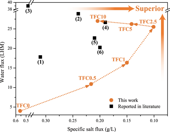
Comparison of the FO performances in this work with those of other sulfonated material-based TFC FO membranes reported in the literature. The serial numbers of the TFC membranes reported in the literature correspond to the NO. in Table 4.
Conclusion
In this work, a low-cost and high-performance TFC FO membrane was prepared using inexpensive PVC as the backbone substrate material and SPSU as the hydrophilic modifier. The FESEM study illustrated that the morphologies of the SPSU/PVC substrates were obviously looser and more porous than that of the neat PVC substrate. By increasing the ratio of SPSU and PVC, the porosity, PWP, surface hydrophilicity, and average pore size of the substrates significantly improved. Furthermore, it was observed that the polyamide active layer of the TFC membranes became rougher, looser and less crosslinked after SPSU was introduced. The A value obviously increased, and the S value dramatically declined. These results suggested that the introduction of SPSU is a feasible strategy to improve the performance and decrease the ICP of TFC membranes. Based on a comprehensive consideration of the properties of the FO membranes and the performance tests, it can be concluded that the SPSU blend ratio of xx% was the optimal blend ratio (e.g., the water flux of TFC2.5 reached xx/xx LMH under the FO/PRO mode using 1.0 M NaCl/DI water as the draw/feed solution, while the specific salt flux exhibited a low value of xx/xx g/L). The comparison studies determined that TFC2.5 exhibited the best FO performance with the lowest sulfonated blend ratio for sulfonated polymer-based TFC membranes. Hence, it is a feasible and low-cost fabrication approach for higher-performance TFC FO membranes using cheap PVC as the backbone material and low blend-ratio SPSU as the modifier material.
Acknowledgements
Financial support from the Ministry of Science and Technology of China for State Key Research and Development Project (2016YFC0400702) is gratefully acknowledged.
Author Contributions
Ke Zheng and Shaoqi Zhou conceived and designed the research. Ke Zheng and Xuan Zhou performed the research and collected the data. Ke Zheng wrote the manuscript and prepared all the figures and tables. All authors reviewed the manuscript.
Competing Interests
The authors declare no competing interests.
Footnotes
Publisher's note: Springer Nature remains neutral with regard to jurisdictional claims in published maps and institutional affiliations.
References
- 1.Qasim M, Darwish NA, Sarp S, Hilal N. Water desalination by forward (direct) osmosis phenomenon: A comprehensive review. Desalination. 2015;374:47–69. doi: 10.1016/j.desal.2015.07.016. [DOI] [Google Scholar]
- 2.Chekli L, et al. A comprehensive review of hybrid forward osmosis systems: Performance, applications and future prospects. Journal of Membrane Science. 2016;497:430–449. doi: 10.1016/j.memsci.2015.09.041. [DOI] [Google Scholar]
- 3.Li D, Yan Y, Wang H. Recent advances in polymer and polymer composite membranes for reverse and forward osmosis processes. Progress in Polymer Science. 2016;61:104–155. doi: 10.1016/j.progpolymsci.2016.03.003. [DOI] [Google Scholar]
- 4.Cai Y, Hu XM. A critical review on draw solutes development for forward osmosis. Desalination. 2016;391:16–29. doi: 10.1016/j.desal.2016.03.021. [DOI] [Google Scholar]
- 5.Wang Y, Ou R, Wang H, Xu T. Graphene oxide modified graphitic carbon nitride as a modifier for thin film composite forward osmosis membrane. Journal of Membrane Science. 2015;475:281–289. doi: 10.1016/j.memsci.2014.10.028. [DOI] [Google Scholar]
- 6.Tian M, Qiu C, Liao Y, Chou S, Wang R. Preparation of polyamide thin film composite forward osmosis membranes using electrospun polyvinylidene fluoride (PVDF) nanofibers as substrates. Separation and Purification Technology. 2013;118:727–736. doi: 10.1016/j.seppur.2013.08.021. [DOI] [Google Scholar]
- 7.Shen L, Xiong S, Wang Y. Graphene oxide incorporated thin-film composite membranes for forward osmosis applications. Chemical Engineering Science. 2016;143:194–205. doi: 10.1016/j.ces.2015.12.029. [DOI] [Google Scholar]
- 8.Duong PHH, et al. Hydroxyl Functionalized Polytriazole-co-polyoxadiazole as Substrates for Forward Osmosis Membranes. Acs Applied Materials & Interfaces. 2015;7:3960–3973. doi: 10.1021/am508387d. [DOI] [PubMed] [Google Scholar]
- 9.Zhou Z, Lee JY, Chung T-S. Thin film composite forward-osmosis membranes with enhanced internal osmotic pressure for internal concentration polarization reduction. Chemical Engineering Journal. 2014;249:236–245. doi: 10.1016/j.cej.2014.03.049. [DOI] [Google Scholar]
- 10.Xu L, Xu J, Shan B, Wang X, Gao C. Novel thin-film composite membranes via manipulating the synergistic interaction of dopamine and m-phenylenediamine for highly efficient forward osmosis desalination. Journal of Materials Chemistry A. 2017;5:7920–7932. doi: 10.1039/C7TA00492C. [DOI] [Google Scholar]
- 11.Qin D, Liu Z, Bai H, Sun DD. Three-dimensional architecture constructed from a graphene oxide nanosheet–polymer composite for high-flux forward osmosis membranes. Journal of Materials Chemistry A. 2017;5:12183–12192. doi: 10.1039/C7TA00741H. [DOI] [Google Scholar]
- 12.Wang Y, Xu T. Anchoring hydrophilic polymer in substrate: An easy approach for improving the performance of TFC FO membrane. Journal of Membrane Science. 2015;476:330–339. doi: 10.1016/j.memsci.2014.11.025. [DOI] [Google Scholar]
- 13.Shaffer DL, Jaramillo H, Castrillon SR-V, Lu X, Elimelech M. Post-fabrication modification of forward osmosis membranes with a poly(ethylene glycol) block copolymer for improved organic fouling resistance. Journal of Membrane Science. 2015;490:209–219. doi: 10.1016/j.memsci.2015.04.060. [DOI] [Google Scholar]
- 14.Lu P, et al. Typical Thin-Film Composite (TFC) Membranes Modified with Inorganic Nanomaterials for Forward Osmosis: A Review. Nanoscience and Nanotechnology Letters. 2016;8:906–916. doi: 10.1166/nnl.2016.2174. [DOI] [Google Scholar]
- 15.Flanagan MF, Escobar IC. Novel charged and hydrophilized polybenzimidazole (PBI) membranes for forward osmosis. Journal of Membrane Science. 2013;434:85–92. doi: 10.1016/j.memsci.2013.01.039. [DOI] [Google Scholar]
- 16.Chen GE, et al. Effect of cellulose triacetate membrane thickness on forward-osmosis performance and application for spent electroless nickel plating baths. Journal of Applied Polymer Science. 2017;134:10. [Google Scholar]
- 17.Kwon S-B, et al. Molecular layer-by-layer assembled forward osmosis membranes. Journal of Membrane Science. 2015;488:111–120. doi: 10.1016/j.memsci.2015.04.015. [DOI] [Google Scholar]
- 18.Qiu C, Qi S, Tang CY. Synthesis of high flux forward osmosis membranes by chemically crosslinked layer-by-layer polyelectrolytes. Journal of Membrane Science. 2011;381:74–80. doi: 10.1016/j.memsci.2011.07.013. [DOI] [Google Scholar]
- 19.Emadzadeh D, Lau WJ, Matsuura T, Rahbari-Sisakht M, Ismail AF. A novel thin film composite forward osmosis membrane prepared from PSf-TiO2 nanocomposite substrate for water desalination. Chemical Engineering Journal. 2014;237:70–80. doi: 10.1016/j.cej.2013.09.081. [DOI] [Google Scholar]
- 20.Yu, Z., Liu, X., Zhao, F., Liang, X. & Tian, Y. Fabrication of a low-cost nano-SiO2/PVC composite ultrafiltration membrane and its antifouling performance. Journal of Applied Polymer Science13210.1002/app.41267 (2015).
- 21.Liu B, Chen C, Zhang W, Crittenden J, Chen Y. Low-cost antifouling PVC ultrafiltration membrane fabrication with Pluronic F 127: Effect of additives on properties and performance. Desalination. 2012;307:26–33. doi: 10.1016/j.desal.2012.07.036. [DOI] [Google Scholar]
- 22.Rabiee H, Vatanpour V, Farahani MHDA, Zarrabi H. Improvement in flux and antifouling properties of PVC ultrafiltration membranes by incorporation of zinc oxide (ZnO) nanoparticles. Separation and Purification Technology. 2015;156:299–310. doi: 10.1016/j.seppur.2015.10.015. [DOI] [Google Scholar]
- 23.Jiang, S., Wang, J., Wu, J. & Chen, Y. Poly(vinyl chloride) and poly(ether sulfone)-g-poly(ether glycol) methyl ether methacrylate blend membranes with improved ultrafiltration performance and fouling resistance. Journal of Applied Polymer Science13210.1002/app.41726 (2015).
- 24.Chi L, et al. Modeling and optimizing the performance of PVC/PVB ultrafiltration membranes using supervised learning approaches. RSC Advances. 2016;6:28038–28046. doi: 10.1039/C5RA24654G. [DOI] [Google Scholar]
- 25.Wang KY, Chung T-S, Amy G. Developing thin-film-composite forward osmosis membranes on the PES/SPSf substrate through interfacial polymerization. Aiche Journal. 2012;58:770–781. doi: 10.1002/aic.12635. [DOI] [Google Scholar]
- 26.Han G, Chung T-S, Toriida M, Tamai S. Thin-film composite forward osmosis membranes with novel hydrophilic supports for desalination. Journal of Membrane Science. 2012;423:543–555. doi: 10.1016/j.memsci.2012.09.005. [DOI] [Google Scholar]
- 27.Zhang X, et al. High performance thin-film composite (TFC) forward osmosis (FO) membrane fabricated on novel hydrophilic disulfonated poly(arylene ether sulfone) multiblock copolymer/polysulfone substrate. Journal of Membrane Science. 2016;520:529–539. doi: 10.1016/j.memsci.2016.08.005. [DOI] [Google Scholar]
- 28.Widjojo N, Chung T-S, Weber M, Maletzko C, Warzelhan V. The role of sulphonated polymer and macrovoid-free structure in the support layer for thin-film composite (TFC) forward osmosis (FO) membranes. Journal of Membrane Science. 2011;383:214–223. doi: 10.1016/j.memsci.2011.08.041. [DOI] [Google Scholar]
- 29.Yu L-Y, Xu Z-L, Shen H-M, Yang H. Preparation and characterization of PVDF-SiO2 composite hollow fiber UF membrane by sol-gel method. Journal of Membrane Science. 2009;337:257–265. doi: 10.1016/j.memsci.2009.03.054. [DOI] [Google Scholar]
- 30.Liu X, Ng HY. Fabrication of layered silica-polysulfone mixed matrix substrate membrane for enhancing performance of thin-film composite forward osmosis membrane. Journal of Membrane Science. 2015;481:148–163. doi: 10.1016/j.memsci.2015.02.012. [DOI] [Google Scholar]
- 31.Lu P, Liang S, Qiu L, Gao Y, Wang Q. Thin film nanocomposite forward osmosis membranes based on layered double hydroxide nanoparticles blended substrates. Journal of Membrane Science. 2016;504:196–205. doi: 10.1016/j.memsci.2015.12.066. [DOI] [Google Scholar]
- 32.Wu C, et al. Preparation of super-hydrophobic PVDF membrane for MD purpose via hydroxyl induced crystallization-phase inversion. Journal of Membrane Science. 2017;543:288–300. doi: 10.1016/j.memsci.2017.08.066. [DOI] [Google Scholar]
- 33.Ren J, O’Grady B, deJesus G, McCutcheon JR. Sulfonated polysulfone supported high performance thin film composite membranes for forward osmosis. Polymer. 2016;103:486–497. doi: 10.1016/j.polymer.2016.02.058. [DOI] [Google Scholar]
- 34.Blanco J-F, Sublet J, Nguyen QT, Schaetzel P. Formation and morphology studies of different polysulfones-based membranes made by wet phase inversion process. Journal of Membrane Science. 2006;283:27–37. doi: 10.1016/j.memsci.2006.06.011. [DOI] [Google Scholar]
- 35.Rabiee H, Shahabadi SMS, Mokhtare A, Rabiei H, Alvandifar N. Enhancement in permeation and antifouling properties of PVC ultrafiltration membranes with addition of hydrophilic surfactant additives: Tween-20 and Tween-80. J. Environ. Chem. Eng. (Netherlands) 2016;4:4050–4061. doi: 10.1016/j.jece.2016.09.015. [DOI] [Google Scholar]
- 36.Ou, R., Wang, Y., Zhang, H., Wang, H. & Xu, T. Preparation of high-flux ultrafiltration membranes by blending strongly charged polymer. Journal of Applied Polymer Science13410.1002/app.44570 (2017).
- 37.Lim S, et al. Dual-layered nanocomposite substrate membrane based on polysulfone/graphene oxide for mitigating internal concentration polarization in forward osmosis. Polymer. 2017;110:36–48. doi: 10.1016/j.polymer.2016.12.066. [DOI] [Google Scholar]
- 38.Li X, Wang KY, Helmer B, Chung T-S. Thin-Film Composite Membranes and Formation Mechanism of Thin-Film Layers on Hydrophilic Cellulose Acetate Propionate Substrates for Forward Osmosis Processes. Industrial & Engineering Chemistry Research. 2012;51:10039–10050. doi: 10.1021/ie2027052. [DOI] [Google Scholar]
- 39.Shen L, Zuo J, Wang Y. Tris(2-aminoethyl)amine in-situ modified thin-film composite membranes for forward osmosis applications. Journal of Membrane Science. 2017;537:186–201. doi: 10.1016/j.memsci.2017.05.035. [DOI] [Google Scholar]
- 40.Sahebi S, et al. Effect of sulphonated polyethersulfone substrate for thin film composite forward osmosis membrane. Desalination. 2016;389:129–136. doi: 10.1016/j.desal.2015.11.028. [DOI] [Google Scholar]
- 41.Tian M, Wang Y-N, Wang R, Fane AG. Synthesis and characterization of thin film nanocomposite forward osmosis membranes supported by silica nanoparticle incorporated nanofibrous substrate. Desalination. 2017;401:142–150. doi: 10.1016/j.desal.2016.04.003. [DOI] [Google Scholar]
Associated Data
This section collects any data citations, data availability statements, or supplementary materials included in this article.
Data Availability Statement
The data of this study are available from the corresponding author on reasonable request.


