Abstract
The aim of the current study is to investigate the effect of radial and cylindrical light distributions on the response of vascular tissue during 1470-nm irradiation in ex vivo models. Due to a low irradiance (5.3 W/cm2) and wide light distribution, cylindrically diffusing irradiation yielded uniform thermal coagulation while radial irradiation accompanied delamination of layers in leporine veins. Bovine foot model testing verified that the diffusing irradiation was associated with the steady maximum temperature and no tissue attachment, compared with the radial irradiation. The proposed cylindrical light application can be a feasible way to treat varicose veins in an effective manner.
OCIS codes: (140.3390) Laser materials processing, (120.6810) Thermal effects, (170.1610) Clinical applications, (170.3660) Light propagation in tissues, (230.1980) Diffusers
1. Introduction
Varicose vein is a blood reflux disease caused by high venous pressure and dysfunctional valves in the saphenous veins [1–3]. The recent reports show that the prevalence of the varicose vein is estimated to be 23% of adults in the United States [4, 5]. In most cases, the varicose veins appear on the lower legs frequently with discomfort, pain, aesthetic problems, reduced quality of life, and even cardiovascular disease [3, 5, 6]. A number of varicose vein treatments have been developed, such as open venous surgery, sclerotherapy drugs, steam bubble generation, varicose radiofrequency closure, endovenous laser ablation (EVLA), and high intensity focused ultrasound [3, 7–9]. Among the treatments, the EVLA procedure was highly recommended by the National Institute for Health and Clinical Excellence as an effective minimally invasive method for truncal vein reflux causing varicose veins due to a high success rate of > 90% [10, 11].
In spite of effective treatment, EVLA is often associated with excessive heating, leading to pain and burning that increase the risk of dermatitis [4, 12]. To reduce these complications, various improvements have been suggested such as various wavelengths (810 to 2000 nm) [13, 14] and optical delivery devices (flat, tulip-shaped, lens-capped, and radial fiber) that are already in use for clinical applications [11, 15]. Strong light absorption by water both in the blood and the vein wall enables the longer wavelengths (1320, 1470, 1885, and 1940 nm) to attain more consistent and marked heating to the vein, eventually reducing postoperative pain [16]. In the case of light delivery, a radial fiber was recently developed to radiate the optical energy in a radial direction. In comparison with the other fiber tips, the circumferential emissions can shorten the transmission distance between the fiber tip and the vein wall, inducing relatively uniform heating [15, 17]. In fact, the radial fiber has been widely used in clinical situations due to acceptable treatment efficacy [18, 19]. However, during 1470-nm EVLA with the radial fiber, a high energy density at the tip was still the main cause of unfavorable thermal injury to the peripheral tissue and even recanalization [15, 20]. Thus, further improvements on the delivery device are still required to ensure safety of EVLA.
The current study used a 10-mm diffusing fiber to achieve cylindrical light distribution along the fiber axis and to treat vein tissue in a circumferential manner for effective EVLA. It was hypothesized that the cylindrical light emissions with low irradiance could attain uniform vein destruction resulting from both longitudinal and radial tissue coagulation. For performance assessments, the 10-mm diffusing fiber was comparatively evaluated with the radial fiber in terms of optical distribution, temperature generation, and histological responses of the venous tissue during 1470-nm EVLA in two different ex vivo models.
2. Materials and methods
2.1 Fiber preparation
Both radial (core diameter = 600 µm and glass cap = 1.8 mm; Diotech Co., Busan, South Korea) and diffusing (core diameter = 600 µm and glass cap = 1.4 mm; TeCure, Busan, South Korea) fibers were prepared for the current comparative study. For preparation of the cylindrically diffusing fiber (active element = 10 mm), a 600-µm multimode fiber (NA = 0.5, Thorlabs Inc., Newton, New Jersey, USA) was used and fabricated. Prior to the fabrication, Tefzel jacket of the fiber was removed with methanol. To avoid energy loss at the distal end, the optical fiber was tapered. Then, a 60-W CO2 laser (λ = 10.6 µm, vi60, Synrad, Mukilteo, Washington) was employed to micro-machine the surface of the optical fiber for cylindrical light distribution. The fiber was fixed at a motorized-stage system consisting of both translational and rotational stages. A lens system was used to focus the CO2 laser beam onto the fiber surface (irradiance = 250 kW/cm2 and stability = ± 7%), which yielded hexagonal groove patterns with high uniformity. After the fabrication, a goniometric measurement in conjunction with a photodiode sensor (PD-300-3W, Ophir, Jerusalem, Israel) was used to validate the spatial light distribution of both the radial and the diffusing fibers in terms of longitudinal and azimuthal emissions. As the photodiode had a limited spectral range of 350~1100 nm, He-Ne laser (λ = 632 nm, power = 2 mW, and stability = ± 2.5%; HNL020LB, Thorlabs, Inc., Newton, New Jersey, USA) was selected as a light source for the measurements. Both the fibers and the photodiode were fixed on adjustable mounts, and the photodiode position was controlled by using LabView software. To measure the longitudinal emission, an aluminum plate with a rectangular aperture (0.5 × 0.5 mm2) was placed between the photodiode and the fiber surface to prevent any diffusive light. The distance between the fiber surface and the aluminum plate was 1 mm. Then, the photodiode was moved at 0.05 mm/s along the fiber. For the azimuthal emission measurements, the fiber was horizontally positioned and the detector was rotated around the fiber tip with a radius of 5 mm. The axis of rotation was perpendicular to the fiber. The center of the rotated circle corresponded to the tip of the radial fiber and the distal end of the diffusing fiber. A step size for the azimuthal measurements was 5°. Due to a low power stability of ± 2.5%, the input power was considered invariant for the measurements. Therefore, all the measured intensities were normalized by dividing each measured value by the maximum value.
2.2 Ex vivo experiment
A 1470-nm diode laser system (FC-W-1470, CNI, Changchun, China) was employed as a light source for two different ex-vivo models: leporine vein and bovine foot models. Table 1 summarizes the treatment conditions for the two ex-vivo models. It should be noted that the different condition was selected for each model due to difference in vein inner diameters (leporine = 2~3 mm vs. bovine = 4~7 mm). To ensure the identical fiber condition, each tested fiber (for radial and diffusing) was carefully cleaned by using an ultrasonic cleaner (SH-1025, Saechan Ultrasonic Co. Ltd., Seoul, Korea) after each experiment. Then, the fiber was measured by using a goniometer to confirm the spatial light distribution for comparison. If the variation in the measured distribution was larger than 15%, the fiber was replaced with the new one.
Table 1. Summary of treatment conditions for two ex-vivo models.
| Ex-vivo model | Power (W) | Pull-back speed (mm/s) | Sample size | Purpose |
|---|---|---|---|---|
| Leporine vein | 5 | 1.5 | 5 | To evaluate thermal responses |
| Bovine foot | 6 | 1 | 4 | To emulate clinical situations |
2.2.1 Leporine vein model
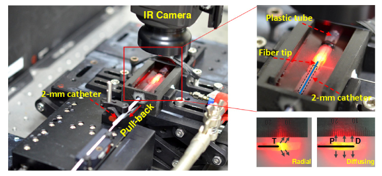
Due to comparable tissue components to human vein, an ex vivo leporine vein model was used to investigate thermal responses during 1470-nm EVLA with both fibers, as shown in Fig. 1. The leporine veins were procured from a local animal center after the animals were euthanized for other experiments, then stored in saline (4°C), and cut in pieces with a total length of 30 mm (25 mm for testing and 5 mm for fixation) and an ID of 2~3 mm prior to the experiments (N = 5). Each vein was fixed by using a plastic tube (a 5 × 25 mm2 rectangle hole in middle of tube) to ensure no movement during EVLA. A catheter (OD = 2 mm) was partially inserted into the vein lumen to firmly position the fiber at the center of the lumen. Each fiber was then attached to an automatic pullback device on a motorized stage and inserted into the catheter and then into the vein lumen. The entire setup was placed in a tank that was filled with warm saline solution (i.e., initial temperature = 30 °C), and the vein surface was exposed slightly above the saline surface for temperature measurements. Before testing, a 10-mL syringe needle was used to fill the lumen with the saline and to push out any air bubble. Based upon the coagulation threshold at 60~80°C, 5-W 1470-nm was selected for testing, and each fiber was pulled back at a constant speed of 1.5 mm/s, yielding a linear endovenous energy density (LEED) of 33.3 J/cm. Additionally, to determine the thermal profiles, EVLA with no pull-back movement was implemented for 7 s with both the fibers. A FLIR A300 IR camera in the extended mode (4 × lens, 320 × 240 pixels, spectral range = 7.5~13.0 µm, and acquisition rate = 60 Hz) was positioned around 80 mm above the sample surface and used to measure the spatio-temporal developments of the temperature from the exposed vein surface. A digital camera (D5100, Nikon Corporation, Tokyo, Japan) was also used to capture the images of the leporine veins before and after EVLA. Transient temperature change (°C/s) was calculated by dividing the measured temperature by irradiation time. The rates of axial shrinkage for both the fibers was estimated by dividing the reduced vein length post-EVLA by the initial vein length (i.e., pre-EVLA). For histological analysis, all of the samples were fixed in 10% neutral buffered formalin and later prepared for histology slides. Each specimen was sliced into 4 µm thickness and stained with hematoxylin and eosin (HE). All the prepared slides were then analyzed by using an optical transmission microscope (ICC50 HD, Leica Camera AG, Wetzlar, Germany). Image J (National Institute of the Health, Bethesda, MD) was applied to detect the boundary of the treated lumens and then to measure the luminal areas including delamination area of the veins before and after EVLA with both the fibers. For efficacy comparison between the two fibers, the rates of area shrinkage were estimated by dividing the amount of the reduced area by the initial luminal area.
Fig. 1.
Experimental setup of ex vivo 1470-nm laser irradiation on leporine veins (T: tip of radial fiber; P: proximal and D: distal tips of diffusing fiber.
2.2.2 Bovine vein model
Based on the previous studies, fresh bovine hind feet (12 ~20 months old, weight 500~600 kg) were procured from a local slaughterhouse and were used to emulate clinical situations [21–23]. Each foot contains subcutaneous veins of 20~25 cm in length and 4~7 mm in ID, which are comparable to clinical conditions for EVLA treatments. In fact, both the bovine foot veins and human leg veins are similar in terms of histological structure [22]. A 3-way-plug valve was connected to an end of each vein to insert each fiber and simultaneously to supply saline solution by using a 50 ml syringe pump (NE-300, Pump Systems Inc., NY, USA) at 10 mL/min, resulting in no significant positive intraluminal pressure [21]. Beside, the pump was operated one cycle with the saline solution to ensure no air bubble in the lumen. A total of four bovine foot models were used to create eight vein specimens (50 mm long) for the EVLA testing; thus, each fiber was tested with four specimens (N = 4). Based upon the previous studies and larger vein size (compared with leporine vein), the 1470-nm laser power was set at 6 W and the pull-back speed was 1 mm/s (i.e., LEED = 60 J/cm) [17, 22]. In fact, LEED used for the current study well corresponded to the treatment range in the clinical study (i.e., 45-120 J/cm) [19]. Each fiber was inserted into the lumen of each vein, and temperature developments from the vein surface were measured and recorded in real-time by using an IR camera without an extended mode 4 × lens (focal distance = 40 cm). A digital camera was also used to record the entire EVLA process in the bovine foot vein. Additionally, the flow rates through the treated veins were quantitatively compared between the two fibers to indirectly evaluate efficacy of EVLA. Initially, saline flew into the one end of the vein, and the amount of saline volume was collected and measured at the other end. A syringe pump was used for the initial saline supply at a flow rate of 10 ml/min. Thus, the flow rate ( = saline volume / time; ml/min) throughout the vein was calculated for indirect comparison (N = 4). All the experiments were performed at room temperature (T0 = 20 °C).
2.2.3 Statistical analysis
For non-parametric statistical analysis, Mann-Whitney U test was used to compare two fiber groups by using SPSS program (SPSS Inc., Chicago, Illinois), and p < 0.05 was considered statistically significant.
3. Results
3.1 Light distribution comparison
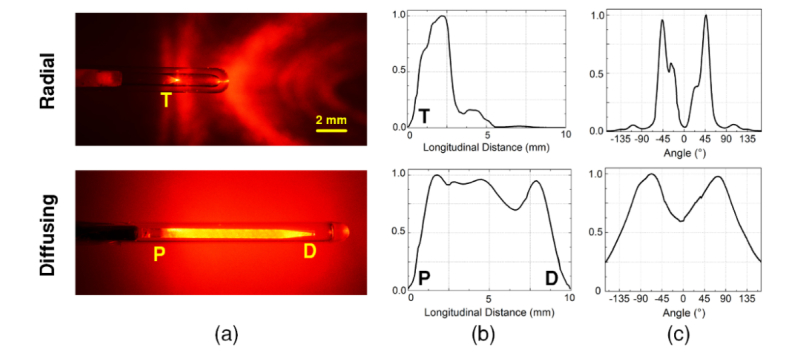
Figure 2(a) shows images of radial and diffusing fibers in conjunction with He-Ne laser light (λ = 632 nm). The He-Ne spatial light distributions qualitatively confirmed that the radial fiber emitted the light in a radial direction from the fiber tip (T) at an angle of around 45° with respect to the fiber axis. On the other hand, the diffusing fiber delivered relatively uniform light distribution along the 10-mm fiber tip between the proximal (P) and the distal ends (D). For quantitative evaluations of the light distribution, Figs. 2(b) and 2(c) display the spatial profiles of the normalized intensity measured from both the fibers. With the radial fiber, the intensity was mainly concentrated between 0.5 and 3.5 mm, accounting for 95% of the transmitted power with the peak intensity positioned 2 mm away from the fiber tip. The diffusing fiber demonstrated a relatively wide profile with 99% of the transmitted power distributed between 0.5 and 9.5 mm. The mean normalized longitudinal intensity was estimated to be 0.87 ± 0.10. From the proximal end of the diffusing fiber, the intensity was almost uniformly maintained but then dropped to approximately 70% at the position of 6.5 mm. Overall, the diffusing fiber yielded a 65% longer active emission length than the radial fiber did. Figure 2(c) exhibits the normalized azimuthal angle emissions from both the fibers. The radial fiber was associated with the narrow peak emissions around ± 45° with respect to the fiber axis. The divergence angle of the emitting beam was estimated to be around 50° (full width at half maximum), representing the angled radial distribution. On the contrary, the diffusing fiber yielded the wider emission profile with two symmetric side-lobes from 0° to 165° and –165° to 0°, indicating the cylindrical distribution. It is also confirmed that no significant difference was found in the emission profiles from both 632 and 1470 nm [24].
Fig. 2.
Comparative evaluations of spatial light distribution from radial and diffusing fibers: (a) He-Ne images, (b) longitudinal emissions, and (c) azimuthal angles (T: tip of radial fiber; P: proximal and D: distal tips of diffusing fiber).
3.2 Leporine vein model
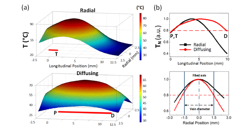
Thermal profiles from the outer vein surface were measured after 7-s irradiation of 5-W 1470 nm (no-pull back the fibers) in order to indirectly evaluate spatial distributions of the temperature induced by radial and diffusing fibers. Figure 3(a) displays the 3D temperature mapping from the captured IR images for stereoscopic evaluations. A red line at the bottom of each graph represents the active tip of each fiber. The radial fiber showed a relatively circular shape with a short temperature distribution whereas the diffusing fiber yielded an elliptical shape with a relatively long uniform temperature distribution. For direct comparison, the measured temperatures from both the fibers were normalized by the corresponding maximum temperatures (normalized temperature: TN) along the longitudinal (top) and radial (bottom) directions as shown in Fig. 3 (b). A red dashed line represents the value that corresponds to 80% of the maximum temperature, which was used as a reference for the comparison. Then, thermal length was defined as a distance corresponding to the temperature distribution above the reference. Apparently, the diffusing fiber yielded a 75% longer thermal length in a longitudinal direction than the radial did (i.e., 9.5 mm for diffusing vs. 5.5 mm for radial). It was noted that TN was almost uniformly distributed from P to D for the diffusing fiber where the uneven distribution was observed from the radial fiber. In addition, the diffusing fiber was associated with a 35% narrower thermal length in a radial direction than the radial fiber (i.e., 3 mm for diffusing vs 4.5 mm for radial). TN with 0.8 or higher for the diffusing fiber was evidently confined within the vein diameter whereas the same TN for the radial fiber reached beyond the vein.
Fig. 3.
Thermal profiles obtained from IR images in leporine veins (P = 5 W, no pull-back, and 7-s after irradiation): (a) 3D temperature profile (top: radial and bottom: diffusing; T: tip of radial fiber; P: proximal and D: distal tips of diffusing fiber) and (b) normalized temperature (TN) along longitudinal (top) and radial directions (bottom).
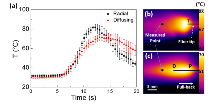
Figure 4 exhibits temperature variations in leporine veins during 1470-nm EVLA with both fibers at 5 W and a pull-back speed of 1.5 mm/s. An IR camera was employed to investigate the temporal developments of the temperature in the tissue as shown in Fig. 4(a). The temperature was acquired from the same fixed position [i.e., black points in Figs. 4(b) and 4(c)] that was 1 cm away from the distal end of the tissue (i.e. 0 mm at tissue end). Thus, the temperature variations commenced at around 6.7 s after the onset of EVLA for both the radial and the diffusing fibers (i.e., 6.7 s = 1 cm / 1.5 mm/s). According to Fig. 4(a), the IR measurements confirm that the radial fiber was associated with a sharp development of the temperature (transient temperature change = 8.7 °C/s). However, the diffusing fiber yielded a relatively gradual development of the temperature and a 40% lower transient temperature change than the radial fiber did (transient temperature change = 5.4 °C/s) with the maximum temperature maintained constantly for around 5 s. In addition, the diffusing fiber induced a 15% lower maximum temperature than the radial fiber did (i.e., 81.7 ± 4.1 °C for radial vs. 71.8 ± 3.8 °C for diffusing; p < 0.05). Figures 4(b) and 4(c) demonstrate the thermal images of the leporine veins captured 17 s after the onset of EVLA with the radial [Fig. 4(b)] and the diffusing [Fig. 4(c)] fibers. Evidently, the radial fiber developed a wide and rather circular thermal distribution in front of the fiber tip (T). On the other hand, the diffusing fiber entailed an elongated thermal profile along the fiber axis with a relatively narrow distribution. It should be noted that both the fibers left the residual heat behind (i.e., left side) due to the fiber movement.
Fig. 4.
Temporal development of (a) temperature in leporine veins at P = 5 W and speed = 1.5 mm/s and 2D thermal images of (b) radial and (c) diffusing irradiation (black point = measured point; T: tip of radial fiber; P: proximal and D: distal tips of diffusing fiber; N = 5).
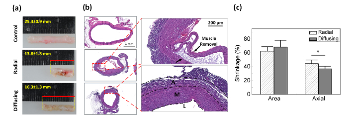
Figure 5(a) shows a comparison of structural deformation in leporine vein tissues after EVLA (5 W and pull-back speed of 1.5 mm/s) with radial and diffusing fibers. Compared with the control, the radial irradiation accompanied substantial tissue shrinkage as well as deformation along with frequent tissue attachment to the fiber during EVLA. In fact, a small fragment of the tissue was often torn off from the vein wall, sticking to the glass cap at the fiber tip. However, the diffusing irradiation yielded uniform discoloration on the entire tissue and almost constant tissue shrinkage along the vein axis after EVLA. According to Fig. 5(b), histology images reveal thermal deformation of the vessel wall structure after EVLA for both the fibers. The radial fiber confirmed partial disintegration of intima and media along with delamination induced by excessive temperature, which shows a good agreement with the previous study [21]. In fact, the excessive heating is the main cause of pain due to unfavorable thermal injury to the peripheral tissue [18, 19]. On the other hand, the diffusing fiber demonstrated constant thermal denaturation on the entire vein wall without any delamination. The degree of area and axial shrinkage was quantified for comparative analysis as shown in Fig. 5(c). Both the radial and diffusing fibers yielded the comparable area shrinkage rates of 62% and 68%, respectively (p = 0.44). However, given the equivalent length of the initial tissue, the radial fiber reduced the tissue length more than the diffusing fiber did after EVLA at 5 W and a pull-back speed of 1.5 mm/s [Figs. 5(a) and 5(c)]. The radial fiber included a 22% higher axial shrinkage rate than the diffusing fiber did (i.e. 44% for radial vs. 36% for diffusing; p <0.05). It was also observed that the radial fiber induced the thicker vein wall than the diffusing fiber did.
Fig. 5.
Thermal response of leporine vein tissues after 5-W 1470-nm laser irradiation: (a) mechanical deformation, (b) histology images and (c) shrinkage rates of area and axial length after EVLA (L: Lumen, M: tunica media, and A: tunica adventitia; N = 5; *: p < 0.05).
3.3 Bovine vein model
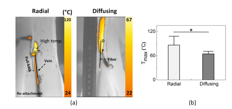
Figure 6(a) shows IR images captured from bovine foot veins during EVLA with radial and diffusing fibers at 6 W and a pull-back speed of 1 mm/s. Both the fibers comparably developed the temperature along the foot vein in the direction of the fiber pull-back movement. The radial fiber accompanied two noticeable cases during EVLA: no tissue attachment and attachment (i.e., three samples for no attachment vs. one sample for attachment). In the case of no tissue attachment, the fiber movement was relatively smooth and experienced continuous vein deformation simultaneously (maximum temperature around 80°C). However, once the tissue attachment occurred to the fiber, the surface temperature of the vein dramatically increased up to 120°C, eventually disturbing the fiber movement due to sticky conditions and leading to tissue charring [Fig. 6(a)]. On the other hand, the diffusing fiber underwent no tissue attachment (i.e., no irregular movement), and continuous thermal deformation was achieved in the vein due to the smooth fiber pull-back. Figure 6(b) compares the maximum surface temperature (Tmax) measured from the bovine foot during 6-W EVLA. Apparently, the diffusing fiber induced a 30% lower maximum temperature than the radial fiber did (i.e., Tmax = 88.4 ± 22.1°C for radial vs. 64.5 ± 6.3°C for diffusing; p <0.005). It was noted that the diffusing irradiation was associated with a more stable maximum temperature increase with a deviation of less than 10%, compared with the radial irradiation (deviation of 25%).
Fig. 6.
Thermal responses of bovine foot veins during 1470-nm EVLA (P = 6 W and speed = 1 mm/s): (a) captured IR images for radial (left) and diffusing (right) irradiation and (b) comparison of maximum temperature (N = 4; *: p < 0.05).
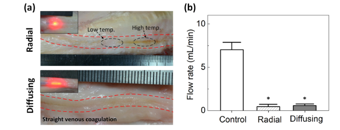
Images of the coagulated vein tissues after EVLA (6 W and pull-back speed of 1 mm/s) were captured to compare the post-EVLA responses of bovine foot veins between radial and diffusing fibers [Fig. 7(a)]. According to Fig. 7(a), the radial irradiation indicated significant fluctuations in tissue coagulation with various degrees of discoloration along the vein (top image). In contrast, the diffusing irradiation yielded almost consistent tissue coagulation in a straight line along the tissue. In an attempt to indirectly evaluate treatment efficacy, the flow rates before and after EVLA were quantitatively estimated in term of saline volume for 2 mins (saline input = 10 mL/min) as shown in Fig. 7(b). Control (normal vein) showed a flow rate of 7.1 ± 0.9 mL/min. On the other hand, the post-EVLA flow rates for both the radial and the diffusing fibers substantially dropped to 0.5 ± 0.3 and 0.6 ± 0.2 mL/min, respectively (p = 0.63), which were almost 92% lower than that of the control (p < 0.05). Thus, after EVLA, the saline hardly passed through the treated veins (i.e., thermally deformed) for both the fibers.
Fig. 7.
Evaluations of post-EVLA on bovine foot veins: (a) images of coagulated vein tissue and (b) quantitative comparison of flow rates among control (normal vein), radial-, and diffusing-treated veins (N = 4; *: p < 0.05 vs. control).
4. Discussion
EVLA has been accepted as an effective method for minimally invasive treatment of truncal vein insufficiency [17, 23]. The amount of laser light to reach the vein wall is a deterministic factor to augment heating efficiency and to induce selective thermal coagulation to the vein wall with minimal injury to the surrounding tissue. Thus, the goal of the current study was to develop and qualify the feasibility of an optical diffusing fiber to heat up the vein wall constantly as well as to generate uniform tissue coagulation during EVLA. Unlike a radial fiber, the proposed fiber was specifically fabricated to irradiate optical energy in a cylindrical manner (Fig. 2) and to cover a large surface of the inner wall with coagulation temperature (60~80 °C) [23]. In fact, the relatively confined thermal profiles within the vein diameter (Fig. 3) could result in a consistent reduction in the cross-sectional area of the vein (Fig. 5) as well as flow rate [Fig. 7(b))]. Both static and dynamic fiber movements also confirmed that the diffusing light distribution was associated with the lower and steadier maximum temperature, compared with the radial irradiation (Figs. 3, 4 and 6). In spite of the lower temperature increase, both the fibers still yielded the comparable deformation of the vein structure (Fig. 5) as well as flow obstruction [Fig. 7(b))]. It should, however, be noted that the radial fiber yielded more axial shrinkage but with thicker vein wall, which could be responsible for the comparable area shrinkage for both the fibers. Moreover, due to the higher maximum temperature and more rapid temperature change, the radial fiber sometimes underwent tissue attachment to the fiber tip and eventually hindered the fiber pull-back movement (Figs. 6 and 7). Conceivably, the tissue attachment with a marked temperature increase could lead to vein perforation and damage to the adjacent tissue if used improperly in clinical situations. Therefore, the cylindrically diffusing irradiation may be another feasible way to treat varicose vein effectively.
According to Fig. 4, a diffusing fiber induced a 15% lower maximum temperature with a 40% lower transient temperature change, compared with a radial fiber. Relatively slower temperature developments for the diffusing fiber were associated with a wide distribution of the laser light (Figs. 3 and 4). Assuming the overall light distribution is perfectly cylindrical, the irradiance (E in W/cm2) on the inner vein surface can be estimated as E = P / A, where P = laser power (W) and A = irradiation area (cm2). The irradiation areas of the radial (Aradial) and the diffusing (Adiffusing) fibers can also be calculated as follows: and , where r = radius of inner vein (mm), α1 = peak emission of angle (45°), α2 = a half of divergence angle (50/2 = 25°), and l = active length (mm). Thus, the irradiance of the diffusing fiber (assuming cylindrical shape in 3-mm leporine vein) could be estimated to be 5.3 W/cm2 at 5 W, which was 65% lower than that of the radial fiber (15.2 W/cm2 at 5 W). In addition, the diffusing fiber yielded a 75% longer thermal length than the radial fiber did (i.e., circular thermal shape for radial vs. elliptical thermal shape for diffusing; Fig. 3), which could be responsible for the lower maximum temperature with the longer plateau phase during dynamic movements of the diffusing fiber (Fig. 4). Therefore, given the conditions, the diffusing fiber could maintain constant temperature (60~80 °C) in the vein wall and reduce undesirable tissue deformation or attachment. Further investigation will apply the equivalent amount of the total fluence (J/cm2) with both the fibers to the vein in order to compare the effect of the equivalent fluence on temperature development and tissue responses.
A radial fiber was associated with direct attachment to the vein wall during EVLA (Figs. 6 and 7), which was also reported in the previous study [17, 20]. When the surface temperature of the vein wall dramatically increases up to 100 °C, the physical properties such as elasticity, wall tension, and metabolic and myogenic effects of tissue can be altered significantly [23, 25]. Thus, the tissue surface can become weak and readily experience physical adhesion to the glass surface of the fiber tip. Upon the adhesion, the tissue could considerably disturb the fiber movement, resulting in insufficient or irregular laser irradiation on the vein wall [20]. Besides, the radial fiber presented slightly less lumen shrinkage (Fig. 5) possibly due to a larger glass cap (i.e., OD = 1.8 mm for radial vs. 1.4 mm for diffusing). In fact, the larger size of the fibers can increase the risk of re-canalization after EVLA [18]. The radial fiber also demonstrated a higher deviation in the maximum temperature increase (i.e., deviation = 20% for radial vs. ≤ 10% for diffusing; Fig. 6). The unstable maximum temperature from the radial irradiation can result from a high probability of the fiber tip making direct contact with the inner vein wall that had the meandering shape. Thus, the direct tissue contact with the glass cap surface could immediately lead to a substantial temperature increase due to a significant change in irradiance (i.e., more 10-fold higher irradiance than that of non-contact). Moreover, the reduced amount of light could be delivered to the non-contact areas (i.e., opposite side of vein wall) due to narrow emissions from the radial fiber. In addition to tissue attachment, excessive tissue coagulation/denaturation or charring could change the local optical properties and the tissue below the location of direct irradiation, resulting in irregular and inconsistent coagulation along the blood vessel. Furthermore, the emission angles around ± 45° from the radial fiber yielded a long irradiation pathway for the light to reach the vein wall, which could be more absorbed by saline during the light transmission. Nevertheless, the radial fiber has been well accepted for clinical EVLA due to high success rates of varicose vein treatment [11, 18]. Therefore, further preclinical or clinical evaluations on the two fibers are still required for the potential clinical translation of the cylindrical irradiation.
Reportedly, blood around the fiber tip is the main cause to circumvent the light transmission to the vein wall and to induce recanalization due to thrombotic effects and steam bubble generation [26]. In clinical situations, the blood inside the vein is often removed and even emptied by using a Trendelenburg position, and tumescent solution is then injected around the vein in order to reduce pain, to protect the perivenous tissue by cooling, and to exert compression around the vein [27, 28]. Recently, F.L. Erzinger compared EVLA with and without tumescence by using a double radial fiber [29]. In spite of half energy density of the radial fiber and 100% occlusion after 30 days, the double radial fiber still involves minor bruising, ecchymosis, and paresthesia, possibly due to a high irradiance [20, 29]. With a narrower thermal length in a radial direction and a constantly lower peak temperature (Figs. 3 and 4), the diffusing fiber may need no local tumescence anesthesia and thus accompany fewer complications after EVLA. Furthermore, the vein wall has three times higher light absorption at 1940 nm than one at 1470 nm (i.e., absorption coefficient, µa,vein = 2.4 mm−1 at 1470 nm vs. 7.5 mm−1 at 1940 nm) [30]. In fact, 1940-nm EVLA was clinically investigated to evaluate its efficacy and safety [31, 32]. Therefore, the diffusing fiber in conjunction with 1940-nm laser light will be tested in vivo with and without tumescence to validate acute and chronic responses of the vein tissue in terms of occlusion rate, recanalization probability, and wound healing.
Although the current study exhibited the feasibility of cylindrically diffusing irradiation to achieve low irradiance as well as uniform tissue coagulation for EVLA, experimental limitations still remained. Due to anatomical and physiological conditions, the tested ex vivo normal tissues hardly reflect pathological features of human varicose veins. In addition, as no chronic response of the vein tissue was observed, the current results are hardly extrapolated to clinical applications. IR temperature measurements merely exhibited the temperature profiles on the outer surface of vein, which could be difficult to evaluate thermal interactions inside the vein. Thus, a variety of temperature sensing methods such as thermocouple, FBG sensor, and volumetric optoacoustic imaging should be considered to ensure the safe application of the proposed diffusing fiber [33, 34]. In spite of no physical damage observed during the experiments, the diffusing fibers should be evaluated in terms of flexibility, mechanical impact, thermal stress, and glass devitrification to treat blood vessels with high curvature. Hence, numerical simulations on the diffuser-assisted EVLA will be conducted to predict thermal and mechanical behaviors of the diffusing fiber in various geometries and testing conditions. In vivo investigations with canine or caprine models will also be performed to evaluate thermos-mechanical tolerance of the cylindrically diffusing irradiation and to optimize treatment parameters for effective EVLA.
5. Conclusion
Effect of radial and cylindrical light distributions on vascular tissue was evaluated ex vivo to achieve effective EVLA. Given the testing conditions, the cylindrically diffusing irradiation with a low irradiance was associated with smooth pull-back movement (no tissue attachment), minimal thermal injury to the surrounding tissue, and uniform thermal coagulation, compared with the radial irradiation. The proposed cylindrical light application can be a feasible way to treat varicose veins in an effective manner. Further, in vivo studies will investigate the complete removal of the diseased vein and healing response of the venous tissue to the cylindrical irradiation.
Funding
Ministry of Oceans and Fisheries, Korea (Marine Biotechnology Program, 20150220).
Disclosures
The authors declare that there are no conflicts of interest related to this article.
References and links
- 1.Zimmet S. E., Boisseau M. R., Kendler M., Dalsing M. C., “Endovenous laser ablation,” Phlebolymphology 14, 51–58 (2007). [Google Scholar]
- 2.Raffetto J. D., Khalil R. A., “Mechanisms of varicose vein formation: valve dysfunction and wall dilation,” Phlebology 23(2), 85–98 (2008). 10.1258/phleb.2007.007027 [DOI] [PubMed] [Google Scholar]
- 3.Kim M. S., Kim J.-Y., Noh S.-C., Choi H.-H., “Thermal characteristics of non-biological vessel phantoms for treatment of varicose veins using high-intensity focused ultrasound,” PLoS One 12(4), e0174922 (2017). 10.1371/journal.pone.0174922 [DOI] [PMC free article] [PubMed] [Google Scholar]
- 4.Gloviczki P., Comerota A. J., Dalsing M. C., Eklof B. G., Gillespie D. L., Gloviczki M. L., Lohr J. M., McLafferty R. B., Meissner M. H., Murad M. H., Padberg F. T., Pappas P. J., Passman M. A., Raffetto J. D., Vasquez M. A., Wakefield T. W., “The care of patients with varicose veins and associated chronic venous diseases: clinical practice guidelines of the Society for Vascular Surgery and the American Venous Forum,” J. Vasc. Surg. 53(5), 2S–48S (2011). 10.1016/j.jvs.2011.01.079 [DOI] [PubMed] [Google Scholar]
- 5.Kaplan R. M., Criqui M. H., Denenberg J. O., Bergan J., Fronek A., “Quality of life in patients with chronic venous disease: San Diego population study,” J. Vasc. Surg. 37(5), 1047–1053 (2003). 10.1067/mva.2003.168 [DOI] [PubMed] [Google Scholar]
- 6.Smith J. J., Guest M. G., Greenhalgh R. M., Davies A. H., “Measuring the quality of life in patients with venous ulcers,” J. Vasc. Surg. 31(4), 642–649 (2000). 10.1067/mva.2000.104103 [DOI] [PubMed] [Google Scholar]
- 7.Goodyear S. J., Nyamekye I. K., “Radiofrequency ablation of varicose veins: Best practice techniques and evidence,” Phlebology 30(2), 9–17 (2015). 10.1177/0268355515592771 [DOI] [PubMed] [Google Scholar]
- 8.Alder G., Lees T., “Foam sclerotherapy,” Phlebology 30(2), 18–23 (2015). 10.1177/0268355515589536 [DOI] [PubMed] [Google Scholar]
- 9.van den Bos R. R., Milleret R., Neumann M., Nijsten T., “Proof-of-principle study of steam ablation as novel thermal therapy for saphenous varicose veins,” J. Vasc. Surg. 53(1), 181–186 (2011). 10.1016/j.jvs.2010.06.171 [DOI] [PubMed] [Google Scholar]
- 10. National Clinical Guideline Centre (UK) , “Varicose Veins in the Legs: The Diagnosis and Management of Varicose Veins” (2013).
- 11.Cowpland C. A., Cleese A. L., Whiteley M. S., “Factors affecting optimal linear endovenous energy density for endovenous laser ablation in incompetent lower limb truncal veins - A review of the clinical evidence,” Phlebology 32(5), 299–306 (2017). 10.1177/0268355516648067 [DOI] [PubMed] [Google Scholar]
- 12.Ontario H. Q., “Endovascular laser therapy for varicose veins: an evidence-based analysis,” Ont. Health Technol. Assess. Ser. 10(6), 1–92 (2010). [PMC free article] [PubMed] [Google Scholar]
- 13.van Ruijven P. W., Poluektova A. A., van Gemert M. J., Neumann H. A., Nijsten T., van der Geld C. W., “Optical-thermal mathematical model for endovenous laser ablation of varicose veins,” Lasers Med. Sci. 29(2), 431–439 (2014). 10.1007/s10103-013-1451-x [DOI] [PubMed] [Google Scholar]
- 14.Vuylsteke M. E., Martinelli T., Van Dorpe J., Roelens J., Mordon S., Fourneau I., “Endovenous laser ablation: the role of intraluminal blood,” Eur. J. Vasc. Endovasc. Surg. 42(1), 120–126 (2011). 10.1016/j.ejvs.2011.03.017 [DOI] [PubMed] [Google Scholar]
- 15.Stokbroekx T., de Boer A., Verdaasdonk R. M., Vuylsteke M. E., Mordon S. R., “Commonly used fiber tips in endovenous laser ablation (EVLA): an analysis of technical differences,” Lasers Med. Sci. 29(2), 501–507 (2014). 10.1007/s10103-013-1475-2 [DOI] [PubMed] [Google Scholar]
- 16.Belyaev A. N., Chabushkin A. N., Khrushchalina S. A., Kuznetsova O. A., Lyapin A. A., Romanov K. N., Ryabochkina P. A., “Investigation of endovenous laser ablation of varicose veins in vitro using 1.885-μm laser radiation,” Lasers Med. Sci. 31(3), 503–510 (2016). 10.1007/s10103-016-1877-z [DOI] [PubMed] [Google Scholar]
- 17.Sroka R., Weick K., Sadeghi-Azandaryani M., Steckmeier B., Schmedt C. G., “Endovenous laser therapy--application studies and latest investigations,” J. Biophotonics 3(5-6), 269–276 (2010). 10.1002/jbio.200900097 [DOI] [PubMed] [Google Scholar]
- 18.Hirokawa M., Kurihara N., “Comparison of bare-tip and radial fiber in endovenous laser ablation with 1470 nm diode laser,” Ann. Vasc. Dis. 7(3), 239–245 (2014). 10.3400/avd.oa.14-00081 [DOI] [PMC free article] [PubMed] [Google Scholar]
- 19.Arslan Ü., Çalık E., Tort M., Yıldız Z., Tekin A. İ., Limandal H. K., Kaygın M. A., Dağ Ö., Erkut B., “More Successful Results with Less Energy in Endovenous Laser Ablation Treatment: Long-term Comparison of Bare-tip Fiber 980 nm Laser and Radial-tip Fiber 1470 nm Laser Application,” Ann. Vasc. Surg. 45, 166–172 (2017). 10.1016/j.avsg.2017.06.042 [DOI] [PubMed] [Google Scholar]
- 20.Hirokawa M., Ogawa T., Sugawara H., Shokoku S., Sato S., “Comparison of 1470 nm laser and radial 2ring fiber with 980 nm laser and bare-tip fiber in endovenous laser ablation of saphenous varicose veins: a multicenter, prospective, randomized, non-blind study,” Ann. Vasc. Dis. 8(4), 282–289 (2015). 10.3400/avd.oa.15-00084 [DOI] [PMC free article] [PubMed] [Google Scholar]
- 21.Schmedt C.-G., Meissner O. A., Hunger K., Babaryka G., Ruppert V., Sadeghi-Azandaryani M., Steckmeier B. M., Sroka R., “Evaluation of endovenous radiofrequency ablation and laser therapy with endoluminal optical coherence tomography in an ex vivo model,” J. Vasc. Surg. 45(5), 1047–1058 (2007). 10.1016/j.jvs.2006.12.056 [DOI] [PubMed] [Google Scholar]
- 22.Sroka R., Weick K., Steckmaier S., Steckmaier B., Blagova R., Sroka I., Sadeghi-Azandaryani M., Maier J., Schmedt C.-G., “The ox-foot-model for investigating endoluminal thermal treatment modalities of varicosis vein diseases,” ALTEX 29(4), 403–410 (2012). 10.14573/altex.2012.4.403 [DOI] [PubMed] [Google Scholar]
- 23.Sroka R., Pongratz T., Siegrist K., Burgmeier C., Barth H., Schmedt C., “Endovenous Laser Application,” Phlebologie 42(03), 121–129 (2013). 10.12687/phleb2134-3-2013 [DOI] [Google Scholar]
- 24.Nguyen T. H., Rhee Y. H., Ahn J. C., Kang H. W., “Circumferential irradiation for interstitial coagulation of urethral stricture,” Opt. Express 23(16), 20829–20840 (2015). 10.1364/OE.23.020829 [DOI] [PubMed] [Google Scholar]
- 25.Iida N., “Physical properties of resistance vessel wall in peripheral blood flow regulation-I. Mathematical model,” J. Biomech. 22(2), 109–117 (1989). 10.1016/0021-9290(89)90033-X [DOI] [PubMed] [Google Scholar]
- 26.Proebstle T. M., Moehler T., Gül D., Herdemann S., “Endovenous treatment of the great saphenous vein using a 1,320 nm Nd:YAG laser causes fewer side effects than using a 940 nm diode laser,” Dermatol. Surg. 31(12), 1678–1683, discussion 1683–1684 (2005). [DOI] [PubMed] [Google Scholar]
- 27.van den Bos R. R., Kockaert M. A., Neumann H. A., Nijsten T., “Technical review of endovenous laser therapy for varicose veins,” Eur. J. Vasc. Endovasc. Surg. 35(1), 88–95 (2008). 10.1016/j.ejvs.2007.08.005 [DOI] [PubMed] [Google Scholar]
- 28. Mordon S. R., Vuylsteke M. E., “Varicose veins: endovenous laser treatment,” in Laser and IPL Technology in Dermatology and Aesthetic Medicine (Springer, 2011), pp. 211–225. [Google Scholar]
- 29.Erzinger F. L., Araujo W. J. B., Junior N., Seme C., Caron F. C., Timi J. R. R., “Comparative study of great saphenous vein ablation in the thigh, with and without tumescence,” J. Vasc. Bras. 15, 217–223 (2016). 10.1590/1677-5449.004616 [DOI] [PMC free article] [PubMed] [Google Scholar]
- 30.Poluektova A. A., Malskat W. S., van Gemert M. J., Vuylsteke M. E., Bruijninckx C. M., Neumann H. A., van der Geld C. W., “Some controversies in endovenous laser ablation of varicose veins addressed by optical-thermal mathematical modeling,” Lasers Med. Sci. 29(2), 441–452 (2014). 10.1007/s10103-013-1450-y [DOI] [PubMed] [Google Scholar]
- 31. Sroka R., Pongratz T., Esipova A., Dikic S., Demhasaj S., Comsa F., Schmedt C.-G., “Endovenous laser therapy for occlusion of incompetent saphenous veins using 1940nm,” in European Conference on Biomedical Optics (Optical Society of America, Munich, Germany, 2015), p. 95420D. [Google Scholar]
- 32. Somunyudan M. F., Topaloglu N., Ergenoglu M. U., Gulsoy M., “Endovenous laser ablation with Tm-Fiber laser,” in Optical Interactions with Tissue and Cells XXII (International Society for Optics and Photonics, 2011), p. 789707. [Google Scholar]
- 33.Pham N. T., Lee S. L., Park S., Lee Y. W., Kang H. W., “Real-time temperature monitoring with fiber Bragg grating sensor during diffuser-assisted laser-induced interstitial thermotherapy,” J. Biomed. Opt. 22(4), 045008 (2017). 10.1117/1.JBO.22.4.045008 [DOI] [PubMed] [Google Scholar]
- 34.Fehm T. F., Deán-Ben X. L., Schaur P., Sroka R., Razansky D., “Volumetric optoacoustic imaging feedback during endovenous laser therapy - an ex vivo investigation,” J. Biophotonics 9(9), 934–941 (2016). 10.1002/jbio.201500210 [DOI] [PubMed] [Google Scholar]


