Abstract
The design and fabrication of a compact diffractive optical element is presented for the sorting of beams carrying orbital angular momentum (OAM) of light. The sorter combines a conformal mapping transformation with an optical fan-out, performing demultiplexing with unprecedented levels of miniaturization and OAM resolution. Moreover, an innovative configuration is proposed which simplifies alignment procedures and further improves the compactness of the optical device. Samples have been fabricated in the form of phase-only diffractive optics with high-resolution electron-beam lithography (EBL) over a glass substrate. A soft-lithography process has been optimized for fast and cheap replica production of the EBL masters. Optical tests with OAM beams confirm the designed performance, showing excellent efficiency and low cross-talk, with high fidelity even with multiplexed input beams. This work paves the way for practical OAM multiplexing and demultiplexing devices for use in classical and quantum communication.
Introduction
During the last decade, Space Division Multiplexing (SDM) has experienced an upsurge of research interest, both in academia and industry, as a possible means to address the ever increasing worldwide demand for bandwidth1. In particular, an implementation of SDM exploiting a set of mutually orthogonal spatial modes, in the so-called Mode Division Multiplexing (MDM), has been considered both for free-space and guided propagation, in which independent channels are carried by coaxially propagating and spatially overlapping modes with the same frequency, therefore improving the spectral efficiency and information capacity of the optical link, proportionally to the number of modes transmitted. Among all the different families of orthogonal modal basis, beams carrying orbital angular momentum (OAM) of light have been demonstrated to provide promising candidates for MDM in the optical range2, both in free-space3 and optical fiber propagation4. Beams carrying OAM present a characteristic azimuthal phase term, exp(iℓφ), being φ the azimuthal coordinate on a plane orthogonal to the propagation direction, and ℓ the orbital angular momentum per photon in units of ħ5,6. A pivotal stage of an optical link based on OAM-MDM is that of (de)multiplexing, i.e., how to form a collimated bunch of orthogonal OAM modes at the source and how to sort them according to their OAM content at the receiver after propagation.
Various techniques have been described and implemented in order to sort a set of multiplexed beams with different OAM values, including interferometric methods7, time-division techniques8, integrated silicon photonics9, coherent detection10, OAM-mode analysers11,12, astigmatic-mode converters13, transformation optics14–16, and rotational Doppler effects17. Among all, one of the most effective methods is represented by transformation optics, mapping (conformally) angular momentum to linear momentum. This involves a unitary transformation converting the azimuthal phase gradients of OAM beams into linear phase gradients (tilted beams), which are then mapped to unique spatial positions by means of a Fourier lens14. The mapping is executed by two optical elements in sequence: the first performing a log-pol coordinate transformation and the second correcting the introduced phase distortion. This method has been widely used as a sorting technique, for example, in recent telecom experiments both in the classical18 and quantum19,20 regimes.
In its first realization, spatial light modulators (SLMs) were exploited to implement the two elements14, which were subsequently replaced by refractive optical components15,16 for efficiency reasons. More recently, diffractive versions21,22 exhibiting a higher level of compactness and miniaturization have been realised. The same setup has been demonstrated to perform multiplexing, with the two elements in reverse order22.
As shown elsewhere14–16, a drawback of this demultiplexing technique is represented by the overlap between neighbouring modes, an unavoidable feature of the design, which is detrimental to the inter-channel cross-talk of the communication system. This can be overcome by using a sparse mode space, but at the expense of discarding many channels included in the sorting bandwidth of the system21,22. Therefore, the measurement bandwidth of the sorter, which is proportional to the Fresnel number of the optics16, should be increased in order to provide a sufficient number of modes after channel selection. This is achievable for instance by either decreasing the focal length or increasing the size of the first element performing optical transformation21. On the other hand, applications in optical fibers could prescribe severe limitations to the number of supported OAM modes, i.e. the maximum ℓ value, and the selection of non-consecutive OAM values could dramatically reduce the number of available channels.
An alternative solution consists in including a fan-out element23, which creates multiple copies extending the phase gradient of the sorted beam, which is focused as before but with a narrower width, thus improving the separation between spots. This reduces the channel overlap without sacrificing modal density, but comes at the cost of increased size and complexity of the system. In its first realization24,25, the fan-out element and the corresponding phase-corrector were realised using spatial light modulators (SLMs) and placed following the two-piece log-polar optics, for a total of at least four optical elements, plus lenses in-between for the Fourier transform.
The possibility to integrate the two optical operations into a single optic has been recently demonstrated26, again with an SLM, thus prohibiting compactness. Therefore, while these solutions are satisfactory for laboratory tests, they are not suitable for industrial implementation in a real-world communication set-up.
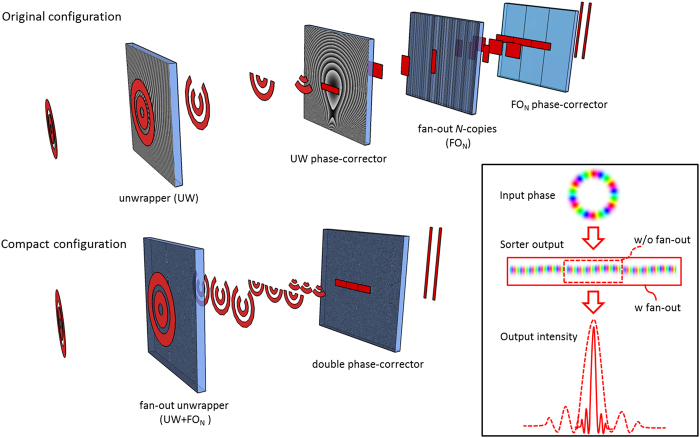
Here we outline a design that allows compactness and efficiency simultaneously, while facilitating ease of production, an important aspect for industrialisation. We fabricate a diffractive solution comprising a first element that performs a log-pol optical transformation, fan-out copying and beam focusing, followed by a double phase-corrector which adjusts the phase distortions introduced by the unwrapping and copying processes (Fig. 1). The two optics are integrated into the same optical platform (few mm in thickness) with a single lithographic exposure and constitute a compact high-resolution OAM sorter that simplifies alignment.
Figure 1.
Comparison of high-resolution OAM sorter configurations. In the original configuration, at least four elements were required: an unwrapper and a phase-corrector, followed by a fan-out array and a second phase-corrector, as well as the ubiquitous lenses for Fourier transform. In the new configuration, high-resolution OAM sorting is performed with two diffractive optics: the first encoding both the optical operations of the unwrapper and the fan-out, and the second performing phase-correction. The inset sketches the output intensity and phase with/without (w/o) the fan-out element.
Results
Sorter design
For the benefit of the reader we briefly summarise the salient points of the design before outlining our compact solution. The optical layout of the sorting system is constituted of two optical elements in sequence: the unwrapper and the phase-corrector. The former performs a conformal mapping of a point (x, y) in the input plane to a point (u, v) in the output plane, where v = a arctan(y/x) and u = −a ln(r/b), being r = (x2 + y2)1/2, a and b design parameters, while the latter corrects the resultant (distorted) phase by taking into account the optical path differences at each point, thus completing the conversion of the input azimuthal phase gradient into a linear one. After applying the coordinate transformation, the field can be described as a truncated tilted plane wave:
| 1 |
where rect(x) = 1 for |x| < 1/2, = 0 otherwise. Therefore, by passing this field through a lens with focal length fT and observing the back focal plane, the tilted plane waves angles are converted into lateral shifts Δsℓ proportional to the OAM amount ℓ according to:
| 2 |
Owing to the non-null width of these spots, there is a significant overlap between the neighbouring modes in the output intensity pattern, which is detrimental when detecting OAM states.
To make the design compact we customized the first element to perform multiple operations at once. The transmission function of this element is then as follows:
| 3 |
and results from the combination of three optical elements. The first term performs the log-pol optical transformation and is given by14
| 4 |
where the two parameters a and b are related to the optical transformation and control the size and the location of the transformed beam, respectively. The parameter a assumes the value L/2π, so that the azimuthal phase gradient is mapped over a length L on the second element in the y-direction, while the position of the unwrapped beam in the x-direction is controlled by the parameter b.
The second contribution encodes the fan-out term and is given by:
| 5 |
This term splits the unwrapped beam into N copies and locates the several copies of the beam side by side on the second optical element; this is achieved by choosing the spatial frequency carriers according to γm = mLk/f. The parameters (cm, δm) are optimized for an equal distribution of the input energy over the several copies27. After phase-correction, the field results in:
| 6 |
which after focusing produces an elongated spot located at the same spacing as before but exhibiting a width scaled as 1/N, therefore reducing the overlap between adjacent spots.
Finally, the lens term provides the focusing of the N-copies of the unwrapped beam on the second optical element, which phase-corrects the field. This element is a double phase-corrector performing the correction of both the log-pol optical transformation and the fan-out process. An analytical formulation of the log-pol phase-corrector exists in the paraxial regime, however the particular choices of focal lengths and beam size in this study require a more precise calculation of the phase patterns beyond the Fresnel regime. Based on angular spectrum diffraction theory28, the rigorous solution of the diffracted field U can be expressed in the convolution algorithm form:
| 7 |
where FT and FT−1 are the Fourier transform and the inverse Fourier transform, respectively, HAS is the angular-spectrum transfer function:
| 8 |
Then the required phase profile for the phase-correcting term is given by
| 9 |
This can be calculated numerically for U0 as an input Gaussian mode with a planar phase front and a beam waist properly chosen in order to illuminate the zone of interest of the first element. In addition, the phase-corrector is endowed with a tilt term to prevent the beam from overlapping with a possible zero-order contribution.
It is well known that traditional OAM sorters are notoriously difficult to align. Moreover, the dual phase-corrector designed in this study requires an even more precise alignment, making it very arduous to obtain output beams of good quality unless the two elements are perfectly planar, coaxial and aligned one to each other. To simplify the alignment process, we designed the sorting configuration in order to incorporate the two elements onto a single optical element.
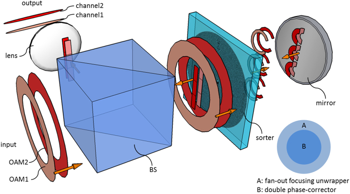
The integration hinges on the fact that OAM beams have a doughnut-like intensity profile around a central null. Since the optical element acts basically on the zone with non-zero input field, the first transformation leaves unexploited the inner region of the optics. Therefore, this central zone can be selected for integrating the second element performing phase-correction. In this novel configuration, the optical element is illuminated twice: after crossing the outer unwrapping zone, the beam is back-reflected with a mirror and impinges on the inner central region providing the phase-corrector (see Fig. 2). Therefore, the total diffractive phase pattern ΩDOE turns out to be the composition of the two phase functions in Eqs (3) and (9):
| 10 |
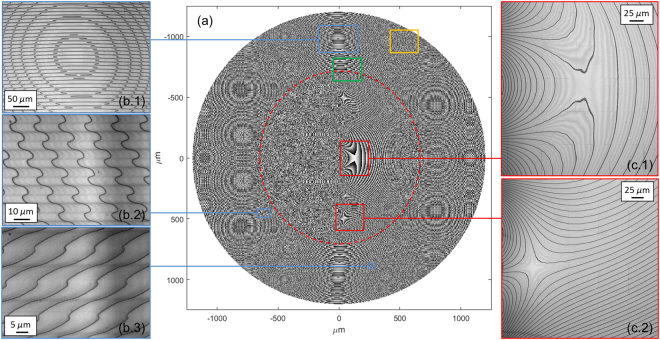
being ρ1 the outer radius of the optics, ρ2 the radius of the central part, Θ the Heaviside function (Θ(x) = 1 for x > 0, Θ(x) = 0 otherwise), providing the condition ρ2 > Nπa is fulfilled. This solution makes the alignment operation significantly easier, since the two elements are by-design aligned, parallel and coaxial one to each other. However, this imposes limitations on the input-beam radius and on the lateral extension of the phase-corrector, i.e. the number of copies N. Figure 3(a) shows the phase pattern calculated for the following optical-transformation parameters: a = 64 μm, b = 900 μm, f = 8.5 mm, three-copies fan-out. The outer radius is equal to 1200 μm. In order to satisfy the above restriction ρ2 > 3πa ( = 603.2 μm), we chose the value ρ2 = 700 μm.
Figure 2.
Schematic of the compact high-resolution sorter. The input OAM beam impinges on the outer annular region (A) of the diffractive optics that encodes the fan-out focusing unwrapper. Subsequently, a mirror reflects the beam towards the optical element again through its inner zone (B), where double phase-correction is performed. A Fourier lens completes the demultiplexing. A beam-splitter (BS) is used to separate input and output beams.
Figure 3.
(a) Phase pattern of log-pol sorter with three-copies fan-out. Parameters of the optical transformation: a = 64 μm, b = 900 μm, f = 8.5 mm, phase-corrector radius (red dashed line) ρ2 = 700 μm, unwrapper outer radius ρ1 = 1200 μm. (b.1-3) Details of the fan-out unwrapper zone at optical microscope. (c.1-2) Details of the double phase-corrector region at optical microscope.
Electron-beam lithography
The designed fan-out sorters were fabricated as surface-relief phase-only diffractive optics. Electron-beam lithography is known to be the best technique to fabricate 3D profiles with nanometric resolution29. By locally controlling the released electronic dose, a different dissolution rate is induced in each zone of the exposed polymer, giving rise to different resist thicknesses after the development process. A dose-depth correlation curve (contrast curve) is required to establish the correct electron-dose to assign to each zone in order to obtain the desired resist thickness. By using custom numerical codes, the transmission phase function of the simulated optics was converted into a 3D multilevel structure, whose local thickness was proportional to the theoretical phase delay, which was in turn transformed into a map of electronic doses. A dose correction for compensating the proximity effects was applied, in order both to match layout depth with the fabricated relief and to obtain a good shape definition, especially in correspondence of the phase discontinuities. In this work, the diffractive-optics phase patterns were written on a PMMA resist layer with a JBX-6300FS JEOL EBL machine, at 5 nm resolution, working at 100 KeV with a current of 100 pA, using a proximity-effect correction assisted ultra-fine process. The substrate used for fabrication was glass-coated ITO with low surface resistivity (8–12 Ω) in order to ensure a good discharge of the sample during electron beam lithography. After the exposure, the resist was developed in a temperature-controlled developer bath for 60 s.
At the experimental wavelength of the laser (λ = 632.8 nm), the PMMA refractive index was assessed to be nPMMA = 1.489, as measured by analysis with a spectroscopic ellipsometer (J.A. Woollam VASE, 0.3 nm spectral resolution, 0.005° angular resolution). For a phase pattern of Ω(x, y), the depth t(x, y) of the exposed zone for normal incidence in air is given by:
| 11 |
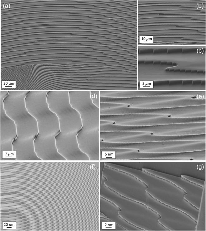
The fabricated optics were made of pixels square matrices with M = 256 phase levels. Each pixel area measures 0.312 × 0.312 μm2. Inserting the values of the laser wavelength and PMMA refractive index into the previous equation, the maximal depth of the surface relief pattern was found to be 1289.0 nm, with a thickness resolution of Δt = 5.1 nm. The quality of the fabricated samples was assessed with optical (Fig. 3) and scanning-electron microscopy (Fig. 4).
Figure 4.
SEM inspection of the 3-copy sorter fabricated with electron-beam lithography and designed for λ = 632.8 nm. Number of phase levels: 256. Maximal thickness step: 1289.0 nm. (a) Zone of transition from the inner (double phase-corrector) to the outer (fan-out unwrapper) region marked by a green line in Fig. 3(a). (b–e) Details. (f) Region marked by an orange line in Fig. 3(a). (g) Exposure of a limited part (40 × 40 μm2) of the region in figure (f) in order to highlight the edge profile.
A soft-lithography replica process of the PMMA masters was fine-tuned and optimized in order to set-up an easy, fast and low-cost fabrication protocol. The optical characterization of the generated copies has demonstrated exceptional fidelity in replicating the 3D structure of the diffractive optics.
Optical characterization
Optical vortices were generated by illuminating a computer-controlled LCoS spatial light modulator (PLUTO-NIR-010-A, Holoeye, 1920 × 1080 pixels, 8 μm pixel size, 8-bit depth) with a linearly polarized Gaussian beam (λ = 632.8 nm, beam waist w0 = 240 μm, power 0.8 mW) emitted by a HeNe laser source. The following phase pattern ΩSLM was uploaded on the SLM display, combining spiral phase and axicon functions with a quadratic contribution for curvature correction:
| 12 |
being α the axicon parameter, k = 2π/λ the wavevector in air, and R the curvature radius of the beam illuminating the display. As outlined in30, a high-order Bessel Gaussian beam is created in the far field, which can be transformed by a Fourier lens into an annular ring, whose radius and width do not depend significantly on the carried OAM and can be controlled by changing the axicon parameter and the input beam-waist. This solution allows limiting the input ring distribution of the OAM beam intensity to the outer region of the optics, encoding the fan-out unwrapper, irrespective of the OAM content for any value of ℓ, ℓ = 0 included. In the experimental setup, a first lens of focal length f1 = 40 cm was used to Fourier-transform the beam reflected by the SLM. At the back focal plane of this lens, a ring was formed having a diameter of RV ≃ αf1/k, topological charge ℓ and a width ΔRV = 2f1/(kw), being w the beam-waist incident on the SLM. With the choice α = 0.22 and w = 873 μm, the OAM beams exhibit ring radius and width around 900 μm and 100 μm, respectively, and well fit the outer annular zone of the optics, which is limited between 700 μm and 1200 μm (see Fig. 3). A 50:50 beam-splitter was used to split the beam and analyze the field profile with a CMOS camera. Next, the generated perfect vortex illuminated the first outer zone of the fan-out sorter, mounted on a 6-axis kinematic mount and placed at the focus of the lens. The transmitted beam was back-reflected by a mirror fixed on a kinematic mount, at a distance equal to half the focal length f of the unwrapping term in Eq. (4), finely adjustable with a micrometric translator. After illuminating the sorter inner zone, the signal was collected by a second CCD placed at the back-focal plane of a second lens with f2 = 12.5 cm.
The optical performance of the fabricated compact sorters was characterized by illuminating, in sequence, with beams carrying OAM in the range from −9 to +9 and recording the intensity profiles.
The area of the CCD was divided into rectangular regions of interest, with the center on each elongated spot in far-field, and a width given by the minimum distance between any two adjacent channels. By integrating the total intensity in each region of interest, the relative modal power and modal cross-talk into neighbouring channels could be determined. The cross-talk XTj on the jth channel was calculated using the following definition:
| 13 |
being Ij,ALL the signal at the jth channel when all the input channels were on, j included, while IALL\j was the same measure when the jth input channel was off.
Then, by utilizing a phase and amplitude modulation technique31 on the SLM, it was additionally possible to study the performance of the sorters with regards to sorting multiplexed OAM modes. Weighted superposition of Laguerre-Gaussian (LG) modes were generated in the first diffraction order of the SLM and imaged through a f-f lens configuration onto the sorter system concatenation of fan-out log-pol elements and the transforming lens. To study the accuracy of multimode beam detection with LG beams, we considered the fan-out log-pol sorter formed by the two elements separated, in sequence, as shown in the Supplementary Fig. 3. Detection and comparison of the relative intensities in the associated CCD bins to the weightings encoded on the hologram for adjacent OAM values provided an indication of the accuracy in demultiplexing multimode OAM beams, i.e., beams comprising several OAM values simultaneously.
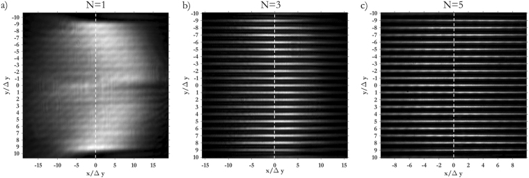
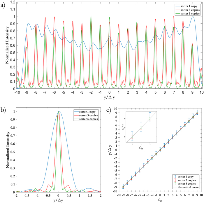
As Figs 5 and 6 show, the width of the focused spots in far-field decreases with the number of copies generated by the fan-out term, as expected. While in the classical sorter consecutive modes are not separated (Fig. 5(a)) and part of the energy is collected by the neighbouring channels (Fig. 7(a)), the integration of the fan-out remarkably improves the resolution of the system. Consecutive OAM modes become clearly separated (Figs 5(b,c), and 6(a)), since the width of the output spots is reduced (Fig. 6(b)). As a consequence, the intensity of off-diagonal terms in the efficiency plots becomes lower (Fig. 7) and the cross-talk of the system is significantly improved (Fig. 8): XT(N = 1, Δℓ = 1) = −3.56 ± 1.02 dB, XT(N = 3, Δℓ = 1) = −5.89 ± 1.95 dB, XT(N = 5, Δℓ = 1) = −9.01 ± 1.94 dB. A further remarkable improvement can be obtained by increasing OAM separation. Limiting to Δℓ = 2, we get: XT(N = 1, Δℓ = 2) = −8.69 ± 1.61 dB, XT(N = 3, Δℓ = 2) = −15.98 ± 2.66 dB, XT(N = 5, Δℓ = 2) = −21.94 ± 4.07 dB.
Figure 5.
Experimental data for OAM beams in the range ℓ = −{9, …, +9} focused after the fan-out log-pol sorter for (a) N = 1 (b), N = 3 and (c), N = 5. As expected, a reduction in spot width is evident as the fan-out multiplication factor N increases. Coordinates have been normalized by the parameter Δy = λf/2πa, such that the vertical position of each spot corresponds to the OAM content of the corresponding beam, according to Eq. (2).
Figure 6.
(a) Cross-sections of the experimental far-field plots in Fig. 5. The vertical coordinate has been normalized by Δy = λf/2πa. (b) Intensity profile of the single peak corresponding to ℓ = 0. (c) Position of the spots as a function of the input OAM value and theoretical curve.
Figure 7.
Output relative power in all detector regions for pure input OAM-beams in the set ℓ = {−9, …, +9}, for different number of copies N of the integrated fan-out log-pol sorter: (a) N = 1, (b) N = 3, (c) N = 5.
Figure 8.
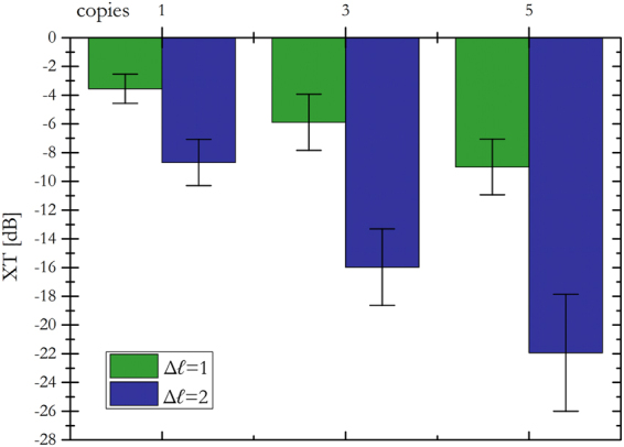
Average inter-channel cross-talk XT for the fan-out log-pol sorter as a function of copies number N = {1, 3, 5} and channel separation Δℓ = {1, 2}. Error bars: standard deviation calculated over the total channel set in the range ℓ = {−9, …, +9}.
Furthermore, analysis of Fig. 9 shows a distinct improvement on the accuracy of multimode OAM beam detection. A superposition of eight OAM modes in the Laguerre-Gaussian basis was created on the SLM, with a modal weighting as shown in the “encoded” plots of Fig. 9. The mode sorters were used to de-multiplex the modes and recover the weighting. We observe a large deviation between the encoded and detected weightings for the conventional sorter, Fig. 9(a), as a result of the increased cross-talk and associated interference between overlapping adjacent modes. This can be seen with the detected weightings of the outer OAM modes in the multiplexed array being significantly smaller than the encoded value while the detected weightings of the modes central to the array have a distinct increase, such that, overall, inaccurate values are detected. A large improvement is clear with the fan-out integration, Fig. 9(b,c), where the relative detected weightings agree well with the encoded values, reaching a similarity (discrete correlation) of over 97%.
Figure 9.
Encoded (multiplexed) and measured (de-multiplexed) superposition weightings for multiplexed OAM modes sent through (a) N = 1, (b) N = 3 and (c) N = 5 integrated copies of the fan-out log-pol mode sorter. The similarity between the multiplexed and de-multiplexed detected modes are S = 0.791, S = 0.968 and S = 0.971 for the cases of N = 1, 3 and 5, respectively.
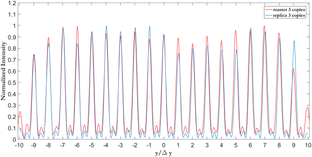
The same optical characterization was performed on the sorters fabricated with soft-lithography replica process from the EBL masters. The generated replica reproduces the optical behaviour of the original sample with high fidelity, as clearly showed in Fig. 10 for the 3-copy sorter. In addition, it is worth noting that the background noise is lower in the replicated sample than in the master. This provides an improvement of the average cross-talk with a value down to XT(N = 3, Δℓ = 1) = −10.26 ± 1.78. This improvement is ascribed to the thermal smoothing of the sample surface after the imprinting process that reduces the roughness with respect to the master, with a consequent drop in scattering losses.
Figure 10.
Comparison between the experimental cross-section of the far field distribution of the master and replica for the sorter with a three-copies fan-out.
Discussion
We designed and fabricated a compact and high-resolution sorter of optical beams carrying orbital angular momentum, by combining the well-known method based on conformal mapping with a fan-out optical operation. The unitary optical transformation is traditionally performed by means of two optical elements, i.e. unwrapper and phase-corrector, which efficiently convert the azimuthal phase gradients of OAM beams into linear phase gradients, then focused at different positions with a Fourier lens. However, due to the inherent diffraction process, neighbouring modes overlap one to each other, which dramatically limits the capability of the system to separate consecutive OAM states. A solution to the problem consists in spatially extending the linear phase gradients, in order to obtain, on the focal plane of the Fourier lens, narrower spots focused at the same positions as before. This was originally achieved by inserting, in sequence to the sorter, a fan-out element creating multiple copies of the beam followed by the corresponding phase-corrector, for a total of at least four elements plus lenses for Fourier transforms.
In this work, the original setup was compacted into two optical elements: a first one, performing both log-pol optical transformation and fan-out, followed by a double phase-corrector. The resulting optical device is markedly simplified and miniaturized as compared to previous demonstrations, while improving sorting performance. Moreover, incorporating the two elements into a single optical platform considerably reduced the alignment difficulty. We fabricated and tested the compact sorters with integrated N-copies fan-out for N = {1, 3, 5}. Electron-beam lithography provided a high-resolution method for the fabrication of the optical elements in the form of high-quality 3D phase-only diffractive optics. The optical performance of the samples has been characterized in terms of efficiency in OAM-mode separation and modal cross-talk. The integration of the fan-out in the sorting system provides a reduction in width of the output spots, therefore decreasing the overlap between neighbouring modes and improving the accuracy in OAM beam detection, as experimentally demonstrated. Cross-talk values down to −10 dB can be achieved without using sparse mode sets as in previous studies21,22. Values below −20 dB can be obtained increasing the OAM separation up to 2, even lower than the cross-talk provided by the standard sorter with a channel separation of 422.
In addition, since electron-beam lithography, while extremely precise, is expensive in terms of time and costs, we considered the possibility to replicate the fabricated optics with faster mass-production methods, in the specific nano-imprinting. To this intent, we optimized a fabrication process for master replica made of UV-cured photopolymers, allowing higher throughput and much lower production costs. The generated replica reproduced the optical behaviour of the original sample with high fidelity, showing even better performance in efficiency and cross-talk.
To conclude, we experimentally demonstrated the possibility to increase the resolution of the sorter based on log-pol conformal mapping by integrating an optical fan-out. The fabrication technique and the new optical architecture remarkably improve the miniaturization level and the compactness of the system and therefore make feasible its integration and industrialisation. This work paves the way for practical OAM multiplexing and demultiplexing devices for use both in classical and quantum communication.
Methods
Numerical simulations
A custom MATLAB code was implemented, based on the convolution algorithm in the angular spectrum regime, in order to compute the propagation of a Gaussian beam impinging on the fan-out unwrapper and therefore calculate the phase pattern of the corresponding dual phase-corrector for phase-distortion correction. The same code was used to calculate the numerical output of the designed diffractive elements and estimate the OAM bandwidth of the sorter on the basis of the design parameters, e.g. log-pol transformation parameters (a, b) and focal length f of the system.
Electron-beam lithography
All the diffractive optics have been fabricated by patterning a layer of PMMA resist (thickness of 2 µm, molecular weight of 950 kg/mol), spin-coated on a 1.1 mm thick ITO coated soda lime float glass substrate and pre-baked for 10 min at 180 °C on a hot plate. The low surface resistivity (8–12 Ω) of the ITO ensures a good discharge of the sample during lithography. From contact profilometry, the dose for a complete removal of the PMMA layer was found to be 566 µC/cm2. The phase patterns were written with a JBX-6300FS JEOL EBL machine, 12 MHz, generating at 100 KeV and 100 pA an electron-beam with a diameter of 2 nm, assuring a resolution down to 5 nm. Few nanometers of gold were sputtered on the surface of the transparent sample to ensure both a better determination of the beam focus and to improve the electron discharge during the exposure. Next, samples were developed for 60 s in a temperature-controlled bath (deionized water: isopropyl alcohol (IPA) 3:7) set on a magnetic stirrer at 1000 rpm. This specific developer was found to be the most suitable choice, providing optimized contrast characteristics and sensitivity as well as minimal surface roughness at the working temperature of 20 °C. After development, the optical elements were gently rinsed in deionized water and blow-dried under nitrogen flux.
Soft-lithography replica
A suitable amount ofthe elastomer Sylgard 184 polydimethylsiloxane (PDMS)base was mixed with the catalyst in a weight ratio of 10:1 respectively, stirred thoroughly, and then cast onto the surface of the EBL fabricated master. The container was placed in a desiccator for30–45 minutes to de‐gas it and remove the trapped air bubbles formed during PDMS pouring and mixing. The sunken master with PDMS prepolymer was then placed into an oven at the temperature of 110 °C to be thermally cured for 30 minutes, then it was left in a freezer for 10 minutes to cool down. This process shrinks the PDMS slightly and helps when peeling the samples out of their molds. In order to fabricate the replica of the mold, a UV-curable photopolymer (Norland Optical Adhesive 74) was dropped onto a glass substrate. The PDMS mold was overlaid on it (with the patterned side facing the liquid) and pressed lightly to form the contact and evacuate the air bubbles trapped under the mold. Different UV-exposure times have been tested in order to fine tune the optimal recipe for best replica production (refer to Supplementary information for further details). The optical performance of the fabricated sorter replica was examined considering sorting efficiency and inter-channel cross-talk, and a UV-curing time of 240 s has been experimentally demonstrated to be the best choice. Afterwards, the PDMS mold was carefully peeled off to get the final replica.
Optical Characterization
The Gaussian beam (λ = 632.8 nm, beam waist w0 = 240 μm, power 0.8 mW) emitted by a HeNe laser source (HNR008R, Thorlabs) is linearly polarized (LPVISE100-A, Thorlabs) before illuminating the display of a LCoS spatial light modulator (PLUTO-NIR-010-A, Holoeye, 1920 × 1080 pixels, 8 μm pixel size, 8-bit depth), combining axicon and spiral phase functions with a quadratic term for curvature correction. The beam reflected by the SLM is Fourier-transformed with a first lens L1 of focal length f1 = 40 cm. Then a 50:50 beam-splitter is used to split the beam and analyze field profile and OAM content at the same time. The field profile is collected with a CMOS camera (DCC1545M, Thorlabs, 1280 × 1024 pixels, 5.2 μm pixel size, monochrome, 8-bit depth). The beam illuminates the first outer zone of the sorter sample, mounted on a 6-axis kinematic mount (K6XS, Thorlabs. Kinematic pitch/yaw: ±4° at 5 mrad/rev, X and Y translation: ±2 mm at 254 µm/rev, continuous 360° goniometer with 1° graduations) and located at the focus of lens L1. A mirror is placed on a kinematic mount (KM100, Thorlabs) and the position is controlled with a micrometric translator (TADC-651, Optosigma). The distance from the sorter is equal to half the focal length f of the unwrapper term. After passing through the sorter inner zone, the signal is collected by a second CCD camera (1500M-GE, Thorlabs, 1392 × 1040 pixels, 6.45 μm pixel size, monochrome, 12-bit depth) placed at the back-focal plane of a lens with f2 = 12.5 cm.
Characterization of the sorter multiplexing ability was accomplished through expansion and collimation of a horizontally polarized HeNe laser beam (λ = 632.8 nm, power 2 mW) onto a phase-only SLM (PLUTO-VIS HoloEye, 8 µm, 1920 × 1080 pixels) with a 10x objective lens and 30.0 cm lens. An f-f system with an aperture in the Fourier plane (FP) isolated and imaged the first order encoded mode onto the first sorting optic. Both sorting optics were mounted on tip-tilt rotational kinematic and translational mounts with a separation distance equal to the design incorporated focal length in the unwrapping term. A 10.0 cm lens was placed f-away from the second, phase-correcting term. The sorted spots formed in the FP were then captured with a Spiricon SP620u CCD camera. Laguerre-Gaussian beam (w0 = 600 μm) superpositions were generated through phase and amplitude modulation with a variation of weightings as indicated by the theoretical black lines in Fig. 9.
Electronic supplementary material
Acknowledgements
This work was supported by SM Optics S.r.l.– SIAE Group and by CEPOLISPE project ‘VORTEX 2’. The authors gratefully thank Ing. Pierangelo Chiappa, Dr. Giuseppe Parisi and Ing. Mauro Zontini for the interesting discussions during this work.
Author Contributions
G.R. and M.G. performed the design and optimization of the sorters phase pattern. M.G. realized optical characterization of the sorters and data analysis in collaboration with G.R. and optimized the soft-lithography replica process. M.M. conducted EBL fabrication and performed optical microscopy. E.M. contributed to replica fabrication and optimization. P.C. performed SEM analyses. B.S. and A.F. contributed to the optical characterisation of the sorters. F.R. proposed and supervised the project. All the authors contributed to the writing of the manuscript.
Competing Interests
The authors declare no competing interests.
Footnotes
Electronic supplementary material
Supplementary information accompanies this paper at 10.1038/s41598-018-28447-1.
Publisher's note: Springer Nature remains neutral with regard to jurisdictional claims in published maps and institutional affiliations.
References
- 1.Agrell E, et al. Roadmap of optical communications. J. Opt. 2016;18:063002. doi: 10.1088/2040-8978/18/6/063002. [DOI] [Google Scholar]
- 2.Yu S. Potential and challenges of using orbital angular momentum communications in optical interconnects. Opt. Express. 2015;23:3075–3087. doi: 10.1364/OE.23.003075. [DOI] [PubMed] [Google Scholar]
- 3.Wang J, et al. Terabit free-space data transmission employing orbital angular momentum multiplexing. Nat. Phot. 2012;6:488–496. doi: 10.1038/nphoton.2012.138. [DOI] [Google Scholar]
- 4.Bozinovic N, et al. Terabit-scale orbital angular momentum mode division multiplexing in fibers. Science. 2013;340:1545–1548. doi: 10.1126/science.1237861. [DOI] [PubMed] [Google Scholar]
- 5.Allen L, Beijersbergen MW, Spreeuw RJC, Woerdman JP. Orbital angular momentum of light and the transformation of Laguerre-Gaussian modes. Phys. Rev. A. 1992;45:8185–8189. doi: 10.1103/PhysRevA.45.8185. [DOI] [PubMed] [Google Scholar]
- 6.Andrews, D. L. & Babiker, M. The Angular Momentum of Light (Cambridge University Press, 2013).
- 7.Leach, J., Padgett, M. J., Barnett, S. M., Franke-Arnold, S. & Courtial, J. Measuring the orbital angular momentum of a single photon. Phys. Rev. Lett. 88, 257901-1-4 (2002). [DOI] [PubMed]
- 8.Bierdz, P., Kwon, M., Roncaioli, C. & Deng, H. High fidelity detection of the orbital angular momentum of light by time mapping. New J. Phys. 15, 113062-1-13 (2013).
- 9.Su T, et al. Demonstration of free space coherent optical communication using integrated silicon photonic orbital angular momentum devices. Opt. Express. 2012;20:9396–9402. doi: 10.1364/OE.20.009396. [DOI] [PubMed] [Google Scholar]
- 10.Belmonte A, Torres JP. Digital coherent receiver for orbital angular momentum demultiplexing. Opt. Lett. 2013;38:241–243. doi: 10.1364/OL.38.000241. [DOI] [PubMed] [Google Scholar]
- 11.Gibson G, et al. Free-space information transfer using light beams carrying orbital angular momentum. Opt. Express. 2004;12:5448–5456. doi: 10.1364/OPEX.12.005448. [DOI] [PubMed] [Google Scholar]
- 12.Ruffato G, Massari M, Romanato F. Diffractive optics for combined spatial- and mode- division multiplexing of optical vortices: design, fabrication and optical characterization. Sci. Rep. 2016;6:24760. doi: 10.1038/srep24760. [DOI] [PMC free article] [PubMed] [Google Scholar]
- 13.Zhou J, Zhang W, Chen L. Experimental detection of high-order or fractional orbital angular momentum of light based on a robust mode converter. App. Phys. Lett. 2016;108:111108. doi: 10.1063/1.4944463. [DOI] [Google Scholar]
- 14.Berkhout, G. C. G., Lavery, M. P. J., Courtial, J., Beijersbergen, M. W. & Padgett, M. J. Efficient sorting of orbital angular momentum states of light. Phys. Rev. Lett. 105, 153601-1-4 (2010). [DOI] [PubMed]
- 15.Lavery MPJ, et al. Refractive elements for the measurements of the orbital angular momentum of a single photon. Opt. Express. 2012;20:2110–2115. doi: 10.1364/OE.20.002110. [DOI] [PubMed] [Google Scholar]
- 16.Lavery MPJ, et al. Efficient measurement of an optical orbital-angular-momentum spectrum comprising more than 50 states. New J. Phys. 2013;15:013024. doi: 10.1088/1367-2630/15/1/013024. [DOI] [Google Scholar]
- 17.Zhou H, et al. Orbital angular momentum complex spectrum analyzer for vortex light based on the rotational Doppler effect. Light Sci. Appl. 2017;6:e16251. doi: 10.1038/lsa.2016.251. [DOI] [PMC free article] [PubMed] [Google Scholar]
- 18.Huang H, et al. Mode division multiplexing using an orbital angular momentum sorter and MIMO-DSP over a graded-index few-mode optical fibre. Sci. Rep. 2015;5:14931. doi: 10.1038/srep14931. [DOI] [PMC free article] [PubMed] [Google Scholar]
- 19.Fickler R, et al. Interface between path and orbital angular momentum entanglement for high-dimensional photonic quantum information. Nat. Commun. 2014;5:4502. doi: 10.1038/ncomms5502. [DOI] [PubMed] [Google Scholar]
- 20.Nape, I., et al High-bit-rate quantum key distribution with entangled internal degrees of freedom of photons. arXiv:1612.09261 (2016).
- 21.Ruffato G, Massari M, Romanato F. Compact sorting of optical vortices by means of diffractive transformation optics. Opt. Lett. 2017;42(3):551–554. doi: 10.1364/OL.42.000551. [DOI] [PubMed] [Google Scholar]
- 22.Ruffato G, Massari M, Parisi G, Romanato F. Test of mode-division multiplexing and demultiplexing in free-space with diffractive transformation optics. Opt. Express. 2017;25:7859–7868. doi: 10.1364/OE.25.007859. [DOI] [PubMed] [Google Scholar]
- 23.Prongué D, Herzig HP, Gale MT. Optimized kinoform structures for highly efficient fan-out elements. Appl. Opt. 1992;31:5706–5711. doi: 10.1364/AO.31.005706. [DOI] [PubMed] [Google Scholar]
- 24.Sullivan MNO, Mirhosseini M, Malik M, Boyd RW. Near-perfect sorting of orbital angular momentum and angular position states of light. Opt. Express. 2012;20:24444–24449. doi: 10.1364/OE.20.024444. [DOI] [PubMed] [Google Scholar]
- 25.Mirhosseini M, Malik M, Shi Z, Boyd RW. Efficient separation of the orbital angular momentum eigenstates of light. Nat. Commun. 2013;4:2781. doi: 10.1038/ncomms3781. [DOI] [PubMed] [Google Scholar]
- 26.Wan, C., Chen, J. & Zhan, Q. Compact and high-resolution optical angular momentum sorter. APL Photonics 2, 031302-1-6 (2017).
- 27.Romero LA, Dickey FM. Theory of optimal beam splitting by phase gratings. I. One-dimensional gratings. J. Opt. Soc. Am. A. 2007;24:2280–2295. doi: 10.1364/JOSAA.24.002280. [DOI] [PubMed] [Google Scholar]
- 28.Li J, Peng Z, Fu Y. Diffraction transfer function and its calculation of classic diffraction formula. Opt. Comm. 2007;280:243–248. doi: 10.1016/j.optcom.2007.08.053. [DOI] [Google Scholar]
- 29.Massari M, Ruffato G, Gintoli M, Ricci F, Romanato F. Fabrication and characterization of high-quality spiral phase plates for optical applications. Appl. Opt. 2015;54:4077–4083. doi: 10.1364/AO.54.004077. [DOI] [Google Scholar]
- 30.Ostrovsky AS, Rickenstorff-Parrao C, Arrizon V. Generation of the “perfect” optical vortex using a liquid-crystal spatial light modulator. Opt. Lett. 2013;38:534–536. doi: 10.1364/OL.38.000534. [DOI] [PubMed] [Google Scholar]
- 31.Rosales-Guzmán, C. & Forbes, A. How to shape light with spatial light modulators (SPIE SPOTLIGHT, 2017).
Associated Data
This section collects any data citations, data availability statements, or supplementary materials included in this article.


