Abstract
Background:
Protective lead or lead-equivalent (Pbeq) aprons play a key role in providing necessary shielding from secondary radiation to occupational workers. Knowledge on the integrity of these shielding apparels during purchase is necessary to maintain adequate radiation safety.
Aim:
The aim of the study was to evaluate the lead equivalence in aprons based on simple quality assessment tool.
Materials and Methods:
0.25 mm and 0.5 mm lead and lead-free aprons from 6 manufacturers were assessed using a calibrated digital X-ray unit. The percentage attenuation values of the aprons were determined at 100 kVp using an ionization chamber and the pixel intensities were analyzed using digital radiographic images of lead apron, copper step wedge tool, and 2 mm thick lead.
Results:
Mean radiation attenuation of 90% and 97% was achieved in 0.25 mm and 0.5 mm lead or lead-free aprons respectively. The pixel intensities from 0.25 mm Pbeq apron correspond to 0.8–1.2 mm thickness of Cu while 0.5 mm Pbeq aprons correspond to 2.0–2.8 mm of Cu.
Conclusion:
Pixel intensity increased with increase in the thickness of copper step wedge indicating a corresponding increase in lead equivalence in aprons. It is suggestive that aprons should be screened for its integrity from the time of purchase using computed tomography (CT), fluoroscopy, or radiography. It is recommended that this simple test tool could be used for checking lead equivalence if any variation in contrast is seen in the image during screening.
Keywords: Attenuation, copper step wedge test tool, lead equivalent aprons, pixel intensity
Introduction
Occupational radiation workers in departments equipped with radiological modalities are required to wear radiation protective apparels for adequate shielding against scatter radiation. Secondary radiation includes both scatter from patient and leakage from the X-ray tube head. Majority of the scatter radiation occurs when the primary X-ray beam interacts with an object causing some of the X-ray beam photons to be scattered. Use of high kV technique results in large amount of scatter radiation, hence shield barriers are provided for occupational workers in radiography rooms. However, when occupational workers are in close proximity to the patient during interventional procedures, adequate lead equivalent (Pbeq) aprons are necessary to protect fromscatter radiation.[1]
Generally, protective apparels consist of vinyl or rubber, impregnated with lead or other shielding material composites, for which their thickness is reported in terms of Pbeq thickness in mm. According to the Medical Guidance report on protective clothing, “Body aprons should have a protective equivalent of not less than 0.25 mm lead for X-rays upto 100 kV and not less than 0.35 mm lead for X-rays over 100 kV.”[2] The Pbeq aprons available in different styles and sizes are selected based on the composition of materials used for radiation protection efficacy, fit, comfort, weight, durability, and ease of maintenance.[3] A typical 0.25 mm lead impregnated apron would weigh approximately 3.25 kg and a 0.5 mm apron would weigh approximately 4.95 kg and may range upto 7 kg, thus causing inconvenience to move around efficiently to perform the desired task.[4,5,6,7] Such aprons worn for long time durations results in musculoskeletal pain and injury especially to the spine.[8,9] To reduce this body strain, recent aprons are manufactured using composite materials containing either lead, cadmium, tin, iodine, barium, antimony, or tungsten providing effective shielding. The composite material based aprons have attenuation equivalent to that achieved using only lead impregnated aprons for X-ray energies ranging from 50kVp to 125kVp with an effective weight reduction of 20–30%.[10]
Owing to a commercial increase in the manufacturing of lead aprons, it is important to test the integrity of every newly purchased apron prior to its usage by radiation personnel. In the recent scenario, emphasis is given to purchase light weight aprons for the ease of work overlooking the integrity of the apron. The radiation protective aprons require screening under radiography, fluoroscopy, or computed tomography (CT) to check for defects periodically from the time of purchase.[11] These defects include non uniformity of the material, cracks, tailoring defects, and variation in the specified lead equivalence provided by the manufacturers. To ensure appropriate lead equivalence in aprons, a simple quality assessment tool was developed in this present study.
Materials and Methods
Quality assessment was performed to check integrity of 12 radiation protective aprons provided by six manufacturers. The weight of the apron was measured using a calibrated digital weighting scale (Guangzhou Weiheng Electronics Co., Ltd). A calibrated Siemens Multix Fusion (Munich, Germany) digital radiography machine was used for obtaining images of the test tool and the apron. The output consistency of the machine was verified using an external dose area product (DAP) meter for standard tube potential of 100kVp and tube load of 32 mAs at a fixed source to detector distance of 100 cm. A lead sheet of 0.5 mm thickness was used as a control to verify the attenuation provided by different lead aprons. The same exposure parameters were used to study the attenuation of the primary X-ray beam in all aprons. The degree of attenuation was calculated by the ratio of the difference in the direct transmission (Toutput) and transmission measured with lead apron (TPb) to the direct transmission without lead apron (Toutput).

A copper step wedge (19 steps) with 0.2 mm thickness progressively increasing with every step and a 2 mm thick reference lead block was placed adjacent to the apron in order to monitor the pixel intensity [Figure 1]. Standard radiographic exposure factors with tube potential of 100 kVp and tube load of 5 mAs was used to study the pixel intensities from the Pbeq apron and the corresponding pixel intensity from the step wedge. Extremity radiography is a non-grid technique and hence this was used as a default setting during the study. This technique is independent of any preset protocol; however, due to the changes in the histogram and the postprocessing in different presets given by different vendors, this study would be reproducible if the same preset protocols are followed. The reference 2 mm lead block was used to monitor the consistency of the pixel intensity measurement for the standardized X-ray output. Mean pixel intensities were measured by placing the region of interest (ROI) on a homogeneous part the apron, step wedge, and lead block using the software available in the GE Centricity PACS workstation (Milwaukee, USA). The mean pixel intensity from the apron was matched with corresponding step (thickness of copper) from step wedge to monitor lead equivalence. The pixel value ratio (PVR) was calculated from mean pixel intensity of the apron and the lead blockand lead block versus Cu step wedge.
Figure 1.
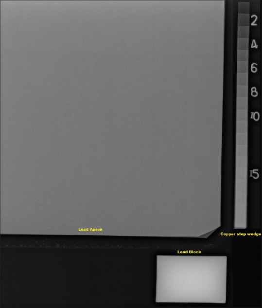
Experimental set-up with apron, copper step wedge, and 2 mm lead block placed adjacent to each other
Results
In this study, a 0.5 mm lead sheet (control) had an attenuation of 98% of the primary X-ray beam for tube potential of 100 kVp. A mean attenuation of 90% and 97% of the primary X-ray beam was demonstrated by 0.25 mm and 0.5 mm aprons respectively as shown in Table 1. Among the 0.5 mm Pbeq aprons, sample 12 and sample 8 showed 98% attenuation and the rest demonstrated an attenuation of 96–97% at 100 kVp.
Table 1.
Lead equivalent aprons showing degree of attenuation and their Pbeq in thickness of copper measured using pixel intensities
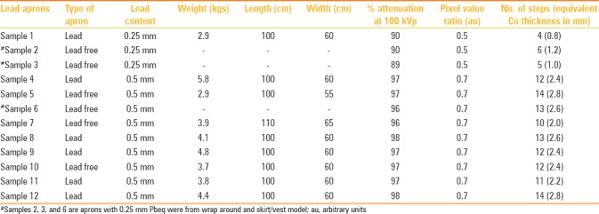
Pixel intensities were measured from apron, lead block, and copper step wedge using an ROI to calculate the PVR and equivalence derived in terms of thickness of the copper. Figure 1 illustrates the set-up with apron, lead block, and copper step wedge. The PVR was found to be constant for 0.5 mm [0.7 arbitary units (au)] and 0.25 mm (0.5 au) lead aprons indicating the consistency in the measurement technique. The mean pixel value for the 2 mm lead block was 2254 and for the 3 mm Cu, it was 1722 (step 15). The mean PVR calculated for the reference block and the different steps from the copper step wedge were consistent for all trials and decreased with increasing thickness of Cu as shown in Figure 2. The mean pixel intensities measured from digital radiographic images with standard preset protocols (in this case, knee anterio posterior (AP) was used as preset) were 1050 for 0.25 mm Pbeq and 1630 for 0.5mm Pb eq. The weight, length, and width of the aprons vary in accordance material/fabric used and is described in Table 1 for single sided (coat type) apron with either 0.25 mm or 0.5 mm Pb eq.
Figure 2.
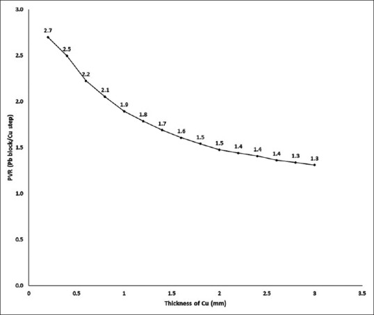
Graph showing thickness of copper versus the pixel value ratio (PVR) calculated against lead block
Discussion
Radiation safety is of concern especially for occupational workers as they are exposed to three-tenth of the annual dose limit of 20 mSv recommended for occupational workers.[12] Majority of the occupational workersare adapted towearing 0.5-mm single sided Pbeq apron while some of them wear wrap around or skirt-vest type of aprons during radiological investigations. Due to prolonged use of heavy aprons during procedures, occupational workers often report physical strain which has led to the introduction of commercially available reduced weight aprons. Weight of aprons are reduced either by selection of fabric material, use of bilayer technology, and use of composite material such as bismuth and antimony with adequate Pbeq for radiation attenuation. Most wrap-around aprons provide 0.5 mm Pbeq in the front side of the apron and 0.25 or 0.35 mm on the rear side of the apron for weight reduction. The bilayer technology with antimony (70%) and tungsten (30%) composition has been tested to reduce weight of aprons by 75% compared to lead based aprons providing the same percentage of attenuation at 100 kVp. Another bilayer combination with barium (60%) and bismuth (40%) was found to provide better attenuation at six different X-ray energies.[13] Though these are commercially available, periodic screening of the aprons to test for Pbeq and integrity related to defects and non-uniformities is crucial from the time of purchase.
Often, screening of lead aprons for qualitative assessment is performed using CT, fluoroscopy, or radiographic imaging to test for integrity of lead apron. In our institution, CT and fluoroscopy are used as amethod of screening lead aprons; however, as shown in this study, digital radiographycan be used for the quantitative assessment of lead equivalence of the apron when defective areas are found during qualitative assessment and which could not be quantified usinga common dosimeter. In our study, various models of lead andlead-free aprons were studied for attenuation and lead equivalence using a ionization chamber and simple step wedge test tool respectively. The 0.5-mm Pbeq aprons showed 96–98% attenuation to primary beam indicating that they had adequate lead equivalence irrespective of lead or composite materials. These results were consistent with reported studies where transmission for pure sample of lead was 5% while transmission for Pbeq materials ranged from 3.5% to 6.7% at 100 kVp.[14] It has also been reported that lead free aprons with 0.5mm lead equivalence was inferior to lead based aprons though its weight was less by one-third of standard lead aprons.[14] These measurements reported in our study have been made for primary beam; however, it should be noted that aprons are basically manufactured for wearers to prevent from scattered radiation. During our study, no correlation between weight and lead equivalence or pixel intensity or percentage attenuation of the aprons were recorded. However, this was not the basic purpose of the current study.
Though the technique of measuring the attenuation using transmission ionization chamber is standard as shown in literature,[15] an alternate and simple method of assessing the lead equivalence has been discussed in this study. Figure 3 illustrates CT and fluoroscopic images showing various defects in newly purchased aprons prior to its usage. These defects include cracks, changes in homogeneity of lead equivalence, lead thinning, combination of 0.25 mm, and 0.5 mm Pbeq materials. Deterioration of the lead-impregnated vinyl is manifested as cracks or holes and may not be visible to the naked eye.[16,17] Our study shows that this simple technique is valid for checking the integrity of the apron. This has been illustrated by considering PVR to be a constant. Moreover, a corresponding increase in the thickness of copper against an increase of lead equivalence in aprons was observed as shown in [Table 1]. The equivalent thickness of copper for 0.25 mm Pbeq apron ranges between 0.8 mm and 1.2 mm and 2.0 mm and 2.8 mm for 0.5 mm Pbeq apron [Figure 4].
Figure 3(A-D).
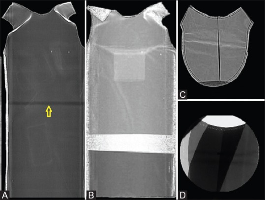
Computed tomography (CT) and fluoroscopic images showing defects in protective apparels.(A) Arrow showing a dark line indicating fragility.(B) Nonuniformity of material.(C) Manufacturing defect inthyroid collar.(D) Different combination of lead equivalent material
Figure 4.
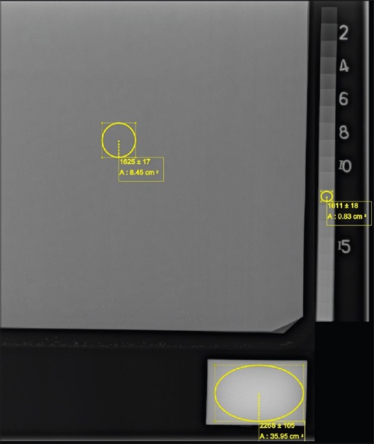
Regions of interest showing pixel intensities of apron, step wedge, and lead block from digital radiographic images
In light of this study, it is important to screen aprons from the time of purchase to check for inconsistencies since there are possibilities in the variations of transmission reproducibilitydue to manufacturing defects, model, batch variations, and lead specifications.[14] In addition, periodic maintenance of lead aprons increases the integrity and life span of the apron. Often only qualified personnel can identify the difference in the Pbeq of 0.25 mm and 0.5 mm thicknesses under radiographic images. This simple technique is an alternative method to assess the Pbeq of the aprons performed using digital radiography. However, standard preset protocols and calibrated X-ray unit is recommended for conducting this study. Open access software such as image J can be used for assessment of pixel values from radiographic images to check for Pb eq.
Conclusion
The study illustrates a simple assessment tool to quantify the lead equivalence of aprons using pixel intensity values. Both lead and lead-free aprons have adequate primary X-ray beam attenuation as demonstrated in this study. Pixel intensities increased with increase in the thickness of copper indicating the increase in lead equivalence in aprons. This study also suggests that users need to screen for integrity of aprons from the time of purchase using either of the modalities such as CT, fluoroscopy, or radiography. Once the discrepancy in the fabric material of the apron is visualized in the image, it is recommended that this simple Pbeq assessment test tool could be used for checking lead equivalence. However, a calibrated radiographic unit and standard protocols for acquiring images should be selected for this assessment.
Financial support and sponsorship
Nil.
Conflicts of interest
There are no conflicts of interest.
References
- 1.Hubbert TE, Vucich JJ, Armstrong MR. Lightweight aprons for protection against scattered radiation during fluoroscopy. Am J Roentgenol. 1993;161:1079–81. doi: 10.2214/ajr.161.5.8273614. [DOI] [PubMed] [Google Scholar]
- 2.York: IPEM; 2002. Institute of Physics and Engineering in Medicine. Medical and Dental Guidance notes: A good practice guide on all aspects of ionising radiation protection in the clinical environment; pp. 60–1. [Google Scholar]
- 3.Meisinger QC, Stahl CM, Andre MP, Kinney TB, Newton IG. Radiation Protection for the Fluoroscopy Operator and Staff. Am J Roentgenol. 2016;207:745–54. doi: 10.2214/AJR.16.16556. [DOI] [PubMed] [Google Scholar]
- 4.Kim SC, Choi JR, Jeon BK. Physical analysis of the shielding capacity for a lightweight apron designed for shielding low intensity scattering X-rays. Sci Rep. 2016;6:27721. doi: 10.1038/srep27721. [DOI] [PMC free article] [PubMed] [Google Scholar]
- 5.Warren-Forward H, Cardew P, Smith B, Clack L, McWhirter K, Johnson S, et al. A comparison of dose savings of lead and lightweight aprons for shielding of 99m-Technetium radiation. Radiat Prot Dosimetry. 2007;124:89–96. doi: 10.1093/rpd/ncm176. [DOI] [PubMed] [Google Scholar]
- 6.Zuguchi M, Chida K, Taura M, Inaba Y, Ebata A, Yamada S. Usefulness of non-lead aprons in radiation protection for physicians performing interventional procedures. Radiat Prot Dosimetry. 2008;131:531–4. doi: 10.1093/rpd/ncn244. [DOI] [PubMed] [Google Scholar]
- 7.Bushong SC. Radiologic Science for Technologists: Physics, Biology, and Protection. Mosby/Elsevier; 2008. pp. 581–98. [Google Scholar]
- 8.Klein LW, Miller DL, Balter S, Laskey W, Haines D, Norbash A, et al. Occupational Health Hazards in the Interventional Laboratory: Time for a Safer Environment. Radiology. 2009;250:538–44. doi: 10.1148/radiol.2502082558. [DOI] [PubMed] [Google Scholar]
- 9.Moore B, vanSonnenberg E, Casola G, Novelline RA. The relationship between back pain and lead apron use in radiologists. Am J Roentgenol. 1992;158:191–3. doi: 10.2214/ajr.158.1.1530763. [DOI] [PubMed] [Google Scholar]
- 10.Webster EW. Experiments with Medium-Z Materials for Shielding Against Low-Energy X Rays. Radiology. 1966;86:146. [Google Scholar]
- 11.Shymko MJ. Minimizing occupational exposure. Radiol Technol. 1998;70:89–90. [PubMed] [Google Scholar]
- 12.Martin CJ, Magee JS. Assessment of eye and body dose for interventional radiologists, cardiologists, and other interventional staff. J Radiol Prot. 2013;33:445–60. doi: 10.1088/0952-4746/33/2/445. [DOI] [PubMed] [Google Scholar]
- 13.McCaffrey JP, Mainegra-Hing E, Shen H. Optimizing non-Pb radiation shielding materials using bilayers. Med Phys. 2009;36:5586–94. doi: 10.1118/1.3260839. [DOI] [PubMed] [Google Scholar]
- 14.Christodoulou EG, Goodsitt MM, Larson SC, Darner KL, Satti J, Chan HP. Evaluation of the transmitted exposure through lead equivalent aprons used in a radiology department, including the contribution from backscatter. Med Phys. 2003;30:1033–8. doi: 10.1118/1.1573207. [DOI] [PubMed] [Google Scholar]
- 15.Finnerty M, Brennan PC. Protective aprons in imaging departments: Manufacturer stated lead equivalence values require validation. Eur Radiol. 2005;15:1477–84. doi: 10.1007/s00330-004-2571-2. [DOI] [PubMed] [Google Scholar]
- 16.Stam W, Pillay M. Inspection of lead aprons: Apractical rejection model. Health Phys. 2008;95(Suppl 2):S133–6. doi: 10.1097/01.HP.0000314763.19226.86. [DOI] [PubMed] [Google Scholar]
- 17.Lambert K, McKeon T. Inspection of lead aprons: Criteria for rejection. Health Phys. 2001;80:S67–9. doi: 10.1097/00004032-200105001-00008. [DOI] [PubMed] [Google Scholar]


